EP0972740B1 - Dispositif de guidage - Google Patents
Dispositif de guidage Download PDFInfo
- Publication number
- EP0972740B1 EP0972740B1 EP99112242A EP99112242A EP0972740B1 EP 0972740 B1 EP0972740 B1 EP 0972740B1 EP 99112242 A EP99112242 A EP 99112242A EP 99112242 A EP99112242 A EP 99112242A EP 0972740 B1 EP0972740 B1 EP 0972740B1
- Authority
- EP
- European Patent Office
- Prior art keywords
- crane
- guiding device
- piston
- rail
- bracket
- Prior art date
- Legal status (The legal status is an assumption and is not a legal conclusion. Google has not performed a legal analysis and makes no representation as to the accuracy of the status listed.)
- Expired - Lifetime
Links
- 230000007246 mechanism Effects 0.000 abstract 2
- 239000000969 carrier Substances 0.000 description 3
- 230000015572 biosynthetic process Effects 0.000 description 1
- 230000008878 coupling Effects 0.000 description 1
- 238000010168 coupling process Methods 0.000 description 1
- 238000005859 coupling reaction Methods 0.000 description 1
- 238000000034 method Methods 0.000 description 1
Images

Classifications
-
- B—PERFORMING OPERATIONS; TRANSPORTING
- B66—HOISTING; LIFTING; HAULING
- B66C—CRANES; LOAD-ENGAGING ELEMENTS OR DEVICES FOR CRANES, CAPSTANS, WINCHES, OR TACKLES
- B66C9/00—Travelling gear incorporated in or fitted to trolleys or cranes
- B66C9/16—Travelling gear incorporated in or fitted to trolleys or cranes with means for maintaining alignment between wheels and track
Definitions
- the invention relates to a guide device for a with wheels provided crane on a crane runway with crane rails according to the preamble of claim 1.
- Such a guide device is already known from DE-A-1 431 951.
- a drive includes one Head carrier that holds two or more wheels.
- the two headbands of the crane are connected by the crane girder.
- Wheel flanges are provided on the running wheels on the crane rails.
- the invention is therefore based on the object of a guide device of the type mentioned above, which is capable of large Compensate for track dimension deviations of the crane runway, being ensured should be that the impellers here in their intended position on the Crane tracks of the crane runway remain.
- the task is solved by a guide device, which has two guide rollers, which are opposite each other in the area the flanks of the crane rail are held by a bracket, the Bracket movable and movable transversely to the longitudinal axis of the crane rails is noticeable.
- the guide device is in this case on the face of the head carrier arranged of the crane.
- Impeller comes from the area of the crane rail.
- the wheels of a crane are not more have to be provided with wheel flanges. Because the function of Wheel flanges are taken over by the console with the guide rollers.
- each Cologne cylinder drive at least one, but preferably two valves are associated with a supply facility, for example an oil container.
- Such control includes another advantageous feature of the invention sensors, the sensors the Determine the current position of the impeller relative to the crane rail. The means that the position of the impeller relative to the sensors Crane rail is then determined in the event that the impeller is too far deviates from the ideal line on the crane track of the crane runway Lock the cylinder of the console, so that another side drift the impeller on the crane rail to prevent.
- the Cranes sensors are arranged.
- the arrangement of the sensors is such that at each end of the head girder on either side of the crane rail one sensor each is arranged on the head carrier. Through these sensors the position of the head carrier and therefore the position of the wheels of the Cranes continuously monitored.
- the arrangement of the Sensors is located on both ends of the other head carrier, i.e. on the head carrier, which has no sensors, one on each end Guide device. From this it is clear that the one head carrier Sensors are assigned, whereas the other, opposite Head carriers with the appropriate guide Guide rollers are assigned assigned consoles.
- the one designated as a whole has 1 Guide device, the housing 10, the console 20 and the Guide rollers 30, 40 on both sides of the crane rail 50 through the Console 20 are held.
- the housing 10 of the guide device is attached to the front of the crane's head girder.
- the console 20 consists of a box-shaped structure 21 which the two axes 31st and 41 of the rollers 30, 40 rotatably receives.
- the console 20 is through the horizontally displaceable slide 11 with the housing 10 connected.
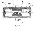
- the two piston-cylinder drives are located in the housing 10 15, 16, the piston rods 15a, 16a of the piston-cylinder drives each engage a coupling element 13.
- This element 13 is mounted in two housing plates 17, 18. These housing plates are again arranged on the carriage 11.
- the carriage 11 is in the Housing 10 stored in that this lateral guide strips 11a has that can be slidably received in the housing 10.
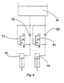
- Each of the piston-cylinder drives 15, 16 stands by two valves 61, 62 or 71, 72 with an oil tank 80 in connection.
- the valves 61, and 71 are designed as one-way solenoid valves, the valves 62, 72 as Check valves. The type of formation of the valves results in Individuals from FIG. 6.
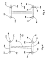
- FIGS. 4 and 5 schematically represent one Crane girder 200 of a crane with two head girders 210 and 220 Head carriers each take two wheels in a row that are not are shown.
- the Guide devices 1 At both front ends of the head support 220 are the Guide devices 1 with the guide rollers 30, 40 arranged.
- the sensors are also in the Area of the respective front end of the head carrier arranged. A the corresponding numbering is shown in Figure 5.
- the sensor 310, 312 reaches the area of the crane rail 50.
- the console presses with the guide roller 30 seen in the direction of travel (arrow 400) behind the head support 220 according to the arrow 250 on the flank of the rail 50, whereas the Guide roller 40 of the console in front of the head carrier on the opposite edge of the crane rail 50 rests (arrow 250).
- sensors 312 and 311 are in the area of crane rail 50 reach. From this it is clear that the crane rails 50 at a such guiding device no longer experiences any horizontal forces, and also completely dispenses with wheel flanges on the wheels can be because the impellers are guided by the guide rollers, and large track deviations of the crane runway can also be compensated for can.
Landscapes
- Engineering & Computer Science (AREA)
- Mechanical Engineering (AREA)
- Carriers, Traveling Bodies, And Overhead Traveling Cranes (AREA)
- Actuator (AREA)
- Crystals, And After-Treatments Of Crystals (AREA)
- External Artificial Organs (AREA)
- Measuring Pulse, Heart Rate, Blood Pressure Or Blood Flow (AREA)
Claims (10)
- Dispositif de guidage (1) pour une grue munie de roues montée sur une voie formée de rails, ledit dispositif de guidage comprenant deux rouleaux de guidage (30, 40) disposés en regard dans la zone du flanc du rail (50) et maintenus par une console (20), ladite console (20) étant mobile transversalement à l'axe longitudinal du rail (50),
caractérisé en ce que
la console est aussi destinée à être verrouillée. - Dispositif de guidage selon la revendication 1,
caractérisé en ce que
le dispositif de guidage (1) est pourvu de deux commandes piston-cylindre (15, 16) disposées l'une en face de l'autre et agissant sur la console (20). - Dispositif de guidage selon la revendication 2,
caractérisé en ce que
chaque commande piston-cylindre (15, 16) est pourvue d'au moins une vanne (61, 62; 71, 72). - Dispositif de guidage selon la revendication 2,
caractérisé en ce que
les commandes piston-cylindre (15, 16) sont des cylindres hydrauliques. - Dispositif de guidage selon la revendication 2,
caractérisé en ce que
les commandes piston-cylindre (15, 16) sont reliés à un organe d'alimentation (80). - Dispositif de guidage selon la revendication 3,
caractérisé en ce que
les vannes (61, 62; 71, 72) sont reliées à une commande. - Dispositif de guidage selon la revendication 6,
caractérisé en ce que
la commande comprend des capteurs (310, 311, 312, 313), les capteurs (310 - 313) détectant la position de la roue (210) par rapport au rail. - Dispositif de guidage selon l'une des revendications précédentes,
caractérisé en ce que
un capteur (310, 311, 312, 313) est prévu, de chaque côté du rail (50), sur le sommier (210) de la grue à chaque extrémité de celui-ci. - Dispositif de guidage selon l'une des revendications précédentes,
caractérisé en ce que
un dispositif de guidage (1) est prévu, sur le sommier (220) d'une grue, à chaque extrémité de celui-ci. - Dispositif de guidage selon la revendication 3,
caractérisé en ce que
le dispositif de guidage (1) est pourvu d'un boítier (10) destiné à recevoir les commandes piston-cylindre (15, 16) ainsi que les vannes (61, 62; 71, 72).
Applications Claiming Priority (2)
| Application Number | Priority Date | Filing Date | Title |
|---|---|---|---|
| DE29812657U | 1998-07-16 | ||
| DE29812657U DE29812657U1 (de) | 1998-07-16 | 1998-07-16 | Führungseinrichtung |
Publications (3)
| Publication Number | Publication Date |
|---|---|
| EP0972740A2 EP0972740A2 (fr) | 2000-01-19 |
| EP0972740A3 EP0972740A3 (fr) | 2001-03-14 |
| EP0972740B1 true EP0972740B1 (fr) | 2002-12-04 |
Family
ID=8059939
Family Applications (1)
| Application Number | Title | Priority Date | Filing Date |
|---|---|---|---|
| EP99112242A Expired - Lifetime EP0972740B1 (fr) | 1998-07-16 | 1999-06-25 | Dispositif de guidage |
Country Status (3)
| Country | Link |
|---|---|
| EP (1) | EP0972740B1 (fr) |
| AT (1) | ATE228964T1 (fr) |
| DE (2) | DE29812657U1 (fr) |
Cited By (1)
| Publication number | Priority date | Publication date | Assignee | Title |
|---|---|---|---|---|
| DE202009008165U1 (de) | 2009-06-13 | 2009-08-27 | Herz, Werner | Führungseinrichtung mit Mitten- und Geradlaufregelung für einen mit Laufrädern versehenen Kran auf einer Kranbahn mit Kranschienen |
Family Cites Families (4)
| Publication number | Priority date | Publication date | Assignee | Title |
|---|---|---|---|---|
| GB1120949A (en) * | 1964-09-22 | 1968-07-24 | Stewarts & Lloyds Ltd | Improvements in or relating to rail transport systems and vehicles therefor |
| DE1431932B2 (de) * | 1965-10-26 | 1970-12-10 | Maschinenfabrik Augsburg-Nürnberg AG, Zweigniederl. Nürnberg, 8500 Nürnberg | Kranbrfickenführung für Verladebrücken oder Laufkrane |
| US5575220A (en) * | 1995-06-20 | 1996-11-19 | Kone Wood Inc. | Side roller assembly for gantry crane bridge wheels |
| FI100594B (fi) * | 1996-09-13 | 1998-01-15 | Kci Kone Cranes Internat Oy | Järjestelmä kiskoja pitkin pyörillä kulkevan laitteen, kuten nosturin sillan ohjaamiseksi |
-
1998
- 1998-07-16 DE DE29812657U patent/DE29812657U1/de not_active Expired - Lifetime
-
1999
- 1999-06-25 EP EP99112242A patent/EP0972740B1/fr not_active Expired - Lifetime
- 1999-06-25 DE DE59903625T patent/DE59903625D1/de not_active Expired - Lifetime
- 1999-06-25 AT AT99112242T patent/ATE228964T1/de not_active IP Right Cessation
Cited By (3)
| Publication number | Priority date | Publication date | Assignee | Title |
|---|---|---|---|---|
| DE202009008165U1 (de) | 2009-06-13 | 2009-08-27 | Herz, Werner | Führungseinrichtung mit Mitten- und Geradlaufregelung für einen mit Laufrädern versehenen Kran auf einer Kranbahn mit Kranschienen |
| EP2261164A2 (fr) | 2009-06-13 | 2010-12-15 | Werner Herz | Dispositif de guidage avec régulation de mouvement rectiligne et centré pour grue équipée de galets de roulement sur chemin de roulement avec rails |
| EP2261164A3 (fr) * | 2009-06-13 | 2011-12-07 | Werner Herz | Dispositif de guidage avec régulation de mouvement rectiligne et centré pour grue équipée de galets de roulement sur chemin de roulement avec rails |
Also Published As
| Publication number | Publication date |
|---|---|
| ATE228964T1 (de) | 2002-12-15 |
| EP0972740A3 (fr) | 2001-03-14 |
| EP0972740A2 (fr) | 2000-01-19 |
| DE59903625D1 (de) | 2003-01-16 |
| DE29812657U1 (de) | 1998-11-05 |
Similar Documents
| Publication | Publication Date | Title |
|---|---|---|
| EP2765101B1 (fr) | Chariot de transport automoteur pour palettes | |
| DE806859C (de) | Verbindungssteg zwischen zwei Eisenbahnwagen | |
| DE9416115U1 (de) | Paletten-Stauförderer | |
| DE2636656C2 (fr) | ||
| DE19522528C2 (de) | Lageranlage mit einer Anzahl von geführten, durch eine Antriebsvorrichtung verfahrbaren Lagereinheiten | |
| DE4220527C2 (de) | Transporteinrichtung für untertägige Strecken | |
| DE202009008165U1 (de) | Führungseinrichtung mit Mitten- und Geradlaufregelung für einen mit Laufrädern versehenen Kran auf einer Kranbahn mit Kranschienen | |
| DE4223095C2 (de) | Lagerung für eine Schienenweiche mit einem Schienenpaar und zwei Weichenzungen | |
| EP0831178A1 (fr) | Voile pour véhicule ferroviaire et véhicule ferroviaire pour une telle voie | |
| DE3145377C2 (de) | Gabelanordnung an einem Lastaufnahmemittel für Förderzeuge | |
| EP1572386A1 (fr) | Laminoir comprenant des moyens pour changer les cylindres | |
| DE3002825A1 (de) | Bodenplatten-anordnung | |
| EP0972740A2 (fr) | Dispositif de guidage | |
| DE69507133T2 (de) | Vorrichtung bei hängeförderern | |
| DE3921123A1 (de) | Trolleyfahrzeug zum ein- und auslagern von speicherguttragenden ladungstraegern | |
| DE3005428C2 (de) | Weiche, insbesondere für Einschienenhängebahnen des Untertagebergbaus | |
| EP0158735A1 (fr) | Appareil de levage et de garage pour avions | |
| DE3625061C1 (de) | Schreitwerk fuer eine Schienenbahn | |
| EP3554912B1 (fr) | Système de transport comprenant un véhicule tracté par câble | |
| CH630699A5 (de) | Drehkreuz mit richtungsbezogener sperre zur bildung eines durchlasses in umzaeunungen, gittern oder anderen absperrungen. | |
| EP1484267A2 (fr) | Transporteur d'accumulation avec chariot | |
| EP0737791A1 (fr) | Système de rails pour éléments de cloison mobiles | |
| DE2802401C3 (de) | Hängebahnanlage | |
| DE3936090C2 (de) | Querverschiebemodul mit Querverschiebeantrieben für einen Transportwagen | |
| DE4305136A1 (de) | Weiche für eine Hängebahn |
Legal Events
| Date | Code | Title | Description |
|---|---|---|---|
| PUAI | Public reference made under article 153(3) epc to a published international application that has entered the european phase |
Free format text: ORIGINAL CODE: 0009012 |
|
| AK | Designated contracting states |
Kind code of ref document: A2 Designated state(s): AT DE FR GB |
|
| AX | Request for extension of the european patent |
Free format text: AL;LT;LV;MK;RO;SI |
|
| PUAL | Search report despatched |
Free format text: ORIGINAL CODE: 0009013 |
|
| AK | Designated contracting states |
Kind code of ref document: A3 Designated state(s): AT BE CH CY DE DK ES FI FR GB GR IE IT LI LU MC NL PT SE |
|
| AX | Request for extension of the european patent |
Free format text: AL;LT;LV;MK;RO;SI |
|
| 17P | Request for examination filed |
Effective date: 20010212 |
|
| AKX | Designation fees paid |
Free format text: AT DE FR GB |
|
| GRAG | Despatch of communication of intention to grant |
Free format text: ORIGINAL CODE: EPIDOS AGRA |
|
| 17Q | First examination report despatched |
Effective date: 20020212 |
|
| GRAG | Despatch of communication of intention to grant |
Free format text: ORIGINAL CODE: EPIDOS AGRA |
|
| GRAG | Despatch of communication of intention to grant |
Free format text: ORIGINAL CODE: EPIDOS AGRA |
|
| GRAH | Despatch of communication of intention to grant a patent |
Free format text: ORIGINAL CODE: EPIDOS IGRA |
|
| GRAH | Despatch of communication of intention to grant a patent |
Free format text: ORIGINAL CODE: EPIDOS IGRA |
|
| GRAA | (expected) grant |
Free format text: ORIGINAL CODE: 0009210 |
|
| AK | Designated contracting states |
Kind code of ref document: B1 Designated state(s): AT DE FR GB |
|
| REF | Corresponds to: |
Ref document number: 228964 Country of ref document: AT Date of ref document: 20021215 Kind code of ref document: T |
|
| REG | Reference to a national code |
Ref country code: GB Ref legal event code: FG4D Free format text: NOT ENGLISH |
|
| GBT | Gb: translation of ep patent filed (gb section 77(6)(a)/1977) |
Effective date: 20021204 |
|
| REF | Corresponds to: |
Ref document number: 59903625 Country of ref document: DE Date of ref document: 20030116 |
|
| ET | Fr: translation filed | ||
| PGFP | Annual fee paid to national office [announced via postgrant information from national office to epo] |
Ref country code: GB Payment date: 20030530 Year of fee payment: 5 |
|
| PGFP | Annual fee paid to national office [announced via postgrant information from national office to epo] |
Ref country code: AT Payment date: 20030603 Year of fee payment: 5 |
|
| PGFP | Annual fee paid to national office [announced via postgrant information from national office to epo] |
Ref country code: FR Payment date: 20030611 Year of fee payment: 5 |
|
| PLBE | No opposition filed within time limit |
Free format text: ORIGINAL CODE: 0009261 |
|
| STAA | Information on the status of an ep patent application or granted ep patent |
Free format text: STATUS: NO OPPOSITION FILED WITHIN TIME LIMIT |
|
| 26N | No opposition filed |
Effective date: 20030905 |
|
| PG25 | Lapsed in a contracting state [announced via postgrant information from national office to epo] |
Ref country code: GB Free format text: LAPSE BECAUSE OF NON-PAYMENT OF DUE FEES Effective date: 20040625 Ref country code: AT Free format text: LAPSE BECAUSE OF NON-PAYMENT OF DUE FEES Effective date: 20040625 |
|
| GBPC | Gb: european patent ceased through non-payment of renewal fee |
Effective date: 20040625 |
|
| PG25 | Lapsed in a contracting state [announced via postgrant information from national office to epo] |
Ref country code: FR Free format text: LAPSE BECAUSE OF NON-PAYMENT OF DUE FEES Effective date: 20050228 |
|
| REG | Reference to a national code |
Ref country code: FR Ref legal event code: ST |
|
| PGFP | Annual fee paid to national office [announced via postgrant information from national office to epo] |
Ref country code: DE Payment date: 20120615 Year of fee payment: 14 |
|
| REG | Reference to a national code |
Ref country code: DE Ref legal event code: R119 Ref document number: 59903625 Country of ref document: DE Effective date: 20140101 |
|
| PG25 | Lapsed in a contracting state [announced via postgrant information from national office to epo] |
Ref country code: DE Free format text: LAPSE BECAUSE OF NON-PAYMENT OF DUE FEES Effective date: 20140101 |