EP0972885A1 - Schwingflügel-Dachfenster - Google Patents
Schwingflügel-Dachfenster Download PDFInfo
- Publication number
- EP0972885A1 EP0972885A1 EP99112507A EP99112507A EP0972885A1 EP 0972885 A1 EP0972885 A1 EP 0972885A1 EP 99112507 A EP99112507 A EP 99112507A EP 99112507 A EP99112507 A EP 99112507A EP 0972885 A1 EP0972885 A1 EP 0972885A1
- Authority
- EP
- European Patent Office
- Prior art keywords
- frame
- guide element
- skylight according
- height
- casement
- Prior art date
- Legal status (The legal status is an assumption and is not a legal conclusion. Google has not performed a legal analysis and makes no representation as to the accuracy of the status listed.)
- Granted
Links
- 230000010355 oscillation Effects 0.000 description 4
- 238000004140 cleaning Methods 0.000 description 2
- 230000006835 compression Effects 0.000 description 2
- 238000007906 compression Methods 0.000 description 2
- 239000011521 glass Substances 0.000 description 2
- 238000009434 installation Methods 0.000 description 2
- 239000011295 pitch Substances 0.000 description 2
- 230000009286 beneficial effect Effects 0.000 description 1
- 238000010276 construction Methods 0.000 description 1
- 238000006073 displacement reaction Methods 0.000 description 1
- 230000000694 effects Effects 0.000 description 1
- 230000005484 gravity Effects 0.000 description 1
- 238000000034 method Methods 0.000 description 1
- 238000004091 panning Methods 0.000 description 1
- 238000009423 ventilation Methods 0.000 description 1
Images


Classifications
-
- E—FIXED CONSTRUCTIONS
- E05—LOCKS; KEYS; WINDOW OR DOOR FITTINGS; SAFES
- E05D—HINGES OR SUSPENSION DEVICES FOR DOORS, WINDOWS OR WINGS
- E05D15/00—Suspension arrangements for wings
- E05D15/40—Suspension arrangements for wings supported on arms movable in vertical planes
- E05D15/406—Suspension arrangements for wings supported on arms movable in vertical planes with pivoted arms and sliding guides
-
- E—FIXED CONSTRUCTIONS
- E04—BUILDING
- E04D—ROOF COVERINGS; SKY-LIGHTS; GUTTERS; ROOF-WORKING TOOLS
- E04D13/00—Special arrangements or devices in connection with roof coverings; Protection against birds; Roof drainage ; Sky-lights
- E04D13/03—Sky-lights; Domes; Ventilating sky-lights
- E04D13/035—Sky-lights; Domes; Ventilating sky-lights characterised by having movable parts
- E04D13/0357—Sky-lights; Domes; Ventilating sky-lights characterised by having movable parts the parts pivoting about an axis supported on a hinged frame or arms
-
- E—FIXED CONSTRUCTIONS
- E04—BUILDING
- E04D—ROOF COVERINGS; SKY-LIGHTS; GUTTERS; ROOF-WORKING TOOLS
- E04D13/00—Special arrangements or devices in connection with roof coverings; Protection against birds; Roof drainage ; Sky-lights
- E04D13/03—Sky-lights; Domes; Ventilating sky-lights
- E04D13/035—Sky-lights; Domes; Ventilating sky-lights characterised by having movable parts
- E04D13/0358—Sky-lights; Domes; Ventilating sky-lights characterised by having movable parts the parts moving, in their own plane, e.g. rolling or sliding, or moving in parallel planes with or without an additional movement, e.g. both pivoting and rolling or sliding
-
- E—FIXED CONSTRUCTIONS
- E05—LOCKS; KEYS; WINDOW OR DOOR FITTINGS; SAFES
- E05D—HINGES OR SUSPENSION DEVICES FOR DOORS, WINDOWS OR WINGS
- E05D15/00—Suspension arrangements for wings
- E05D15/48—Suspension arrangements for wings allowing alternative movements
-
- E—FIXED CONSTRUCTIONS
- E05—LOCKS; KEYS; WINDOW OR DOOR FITTINGS; SAFES
- E05Y—INDEXING SCHEME ASSOCIATED WITH SUBCLASSES E05D AND E05F, RELATING TO CONSTRUCTION ELEMENTS, ELECTRIC CONTROL, POWER SUPPLY, POWER SIGNAL OR TRANSMISSION, USER INTERFACES, MOUNTING OR COUPLING, DETAILS, ACCESSORIES, AUXILIARY OPERATIONS NOT OTHERWISE PROVIDED FOR, APPLICATION THEREOF
- E05Y2201/00—Constructional elements; Accessories therefor
- E05Y2201/20—Brakes; Disengaging means; Holders; Stops; Valves; Accessories therefor
- E05Y2201/214—Disengaging means
-
- E—FIXED CONSTRUCTIONS
- E05—LOCKS; KEYS; WINDOW OR DOOR FITTINGS; SAFES
- E05Y—INDEXING SCHEME ASSOCIATED WITH SUBCLASSES E05D AND E05F, RELATING TO CONSTRUCTION ELEMENTS, ELECTRIC CONTROL, POWER SUPPLY, POWER SIGNAL OR TRANSMISSION, USER INTERFACES, MOUNTING OR COUPLING, DETAILS, ACCESSORIES, AUXILIARY OPERATIONS NOT OTHERWISE PROVIDED FOR, APPLICATION THEREOF
- E05Y2201/00—Constructional elements; Accessories therefor
- E05Y2201/40—Motors; Magnets; Springs; Weights; Accessories therefor
- E05Y2201/404—Function thereof
- E05Y2201/422—Function thereof for opening
- E05Y2201/426—Function thereof for opening for the initial opening movement
-
- E—FIXED CONSTRUCTIONS
- E05—LOCKS; KEYS; WINDOW OR DOOR FITTINGS; SAFES
- E05Y—INDEXING SCHEME ASSOCIATED WITH SUBCLASSES E05D AND E05F, RELATING TO CONSTRUCTION ELEMENTS, ELECTRIC CONTROL, POWER SUPPLY, POWER SIGNAL OR TRANSMISSION, USER INTERFACES, MOUNTING OR COUPLING, DETAILS, ACCESSORIES, AUXILIARY OPERATIONS NOT OTHERWISE PROVIDED FOR, APPLICATION THEREOF
- E05Y2201/00—Constructional elements; Accessories therefor
- E05Y2201/40—Motors; Magnets; Springs; Weights; Accessories therefor
- E05Y2201/47—Springs
- E05Y2201/478—Gas springs
-
- E—FIXED CONSTRUCTIONS
- E05—LOCKS; KEYS; WINDOW OR DOOR FITTINGS; SAFES
- E05Y—INDEXING SCHEME ASSOCIATED WITH SUBCLASSES E05D AND E05F, RELATING TO CONSTRUCTION ELEMENTS, ELECTRIC CONTROL, POWER SUPPLY, POWER SIGNAL OR TRANSMISSION, USER INTERFACES, MOUNTING OR COUPLING, DETAILS, ACCESSORIES, AUXILIARY OPERATIONS NOT OTHERWISE PROVIDED FOR, APPLICATION THEREOF
- E05Y2900/00—Application of doors, windows, wings or fittings thereof
- E05Y2900/10—Application of doors, windows, wings or fittings thereof for buildings or parts thereof
- E05Y2900/13—Type of wing
- E05Y2900/148—Windows
- E05Y2900/152—Roof windows
Definitions
- the invention relates to a roof window, in particular Swing-wing roof window, with a frame and a sash that hinges by means of subframe profiles arranged by one Swing axis is pivotally mounted, wherein the oscillation axis runs horizontally and approximately located in the middle of the casement, and with one, at least on one of the longitudinal spars of the Casement arranged guide element, the along the swing opening of the casement a guideway formed on the frame moves which are related to the plane of the top of the Frame at different heights lies.
- swing wing roof windows have the Advantage that, for example, for cleaning the Outside of the glazing around the swing axis in such a way can be pivoted far that the outer glass surface can be cleaned from the interior.
- the swing axis is therefore not only an option the ventilation position (swing opening position), but also a simple exterior glass cleaning.
- roof windows especially residential roof windows, known, which is designed as a hinged window are, that is, the window sash is in the area of the upper frame cross-section pivotally mounted. While with a swing window as a result of arrangement of the swing axis close to the center of gravity Open a not too large torque applied must be due to a hinged window of the weight of the casement Torque a correspondingly greater force for a Opening the window necessary.
- swing windows that are known both a folding movement and a swinging movement of the casement.
- the one here Invention is concerned with swing windows or with hinged swing windows. This means, the sash is always about one in his oscillating axis in the central area is movable stored.
- each longitudinal spar of the casement becomes a guide element assigned, for example the Has the shape of a guide pin.
- This sideways pass through outwardly projecting guide elements when the roof window swings a track. Because the swing axis is at a distance to the respective guide element of the casement lies in the swing opening movement Subframe profiles issued, taking place simultaneously the respective guide element along the assigned guide track moves.
- the invention is therefore based on the object Occurrence of the extreme cases mentioned above in to avoid practice, that is, the casement should remain in the desired open position.
- this object is achieved by that the guideway between its two end areas at least one the sash in the desired Height deflection holding the swing opening position for the guide element. Because of the height deflection lies for the assigned guide element an obstacle that only increased by Overcoming force on the window sash can be. As a result, the guide element remains in the resulting from the height redirection Position so that an automatic adjustment of the wing does not occur.
- the height redirection on the other hand hinders the opening movement or closing movement of the casement is not there the guide element overcome the vertical deflection can, provided the increased effort on the Wing is exercised, for example by train or User pressure on the handle of the casement.
- the deflection one to the level of Top of the frame has a convex shape.
- the Deflection a the level of the top of the Frame is outstanding elevation.
- the guide element runs on the other, opposite Flank of the elevation respectively the corresponding flank of the convex shape, so that there is a fixation of the position of the Sash adjusts.
- the level of the casement for example vertical.
- the height deflection one for Level the top of the frame concave shape having.
- the redirect one in the plane of the top recess in the frame is.
- the pitch angle on the convex side Form or elevation against which the guide element when swing opening the casement tariffs is larger than on the side of the convex shape or elevation, against which the guide element when closing the casement starts up. Accordingly, there is an asymmetry before, which causes that when opening the casement a greater force to overcome the change in altitude is required than when closing.
- the spring device acts particularly in the initial region of the opening particularly strong when this first opening movement particularly supported by an additional spring becomes.
- the attachment part preferably has a support pan for the one already mentioned, which forms an oscillation aid Spring device on.
- the spring device is preferred as an axially acting spring element, in particular telescopic spring element.
- she can be realized for example by means of a gas pressure spring be, preferably each longitudinal spar such a gas pressure spring assigned to the casement is.
- the attachment of the respective gas pressure spring takes place swiveling on the casement, whereby the free end of the respective gas pressure spring on the frame, preferably on the attachment part, namely in the support pan formed there, supports. If the sash is in the course of Opening movement over a certain opening angle open out, so lifts the free end of each Spring device off, that is, it leaves the pan-shaped support bracket.
- the guide element has a circular or non-circular cross section having. If the guiding element is a does not have a circular cross-section, it leads a swiveling movement when going through the height deflection around its longitudinal axis. This panning requires an additional effort, the beneficial to the fixation of each Sash position affects.
- the height deflection as in particular closed on three sides Height deflection channel is formed.
- the guide element protrudes into the open side of the Height diversion channel into it and there both led above as well as below, the distance of the Channel walls can be chosen such that the Guide element a little play in the height deflection channel has or even a slight clamping effect is achieved in certain sections the guideway can be larger or smaller, for example in the areas where there is a fixation of the casement is desired. Is too it is possible to reduce the friction along the guideway set differently.
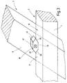
- the roof window 1 shows a roof window 1 in side view, that is in the open swing position located.
- the roof window 1 is as Folding / swing-wing skylights designed. It has a frame 2 and a sash 3rd on.
- the one for installation in a not shown Cover frame 2 provided has two longitudinal spars running parallel to each other 4 and two also spaced parallel to each other extending crossbars 5. is corresponding the sash 3 spaced parallel to one another longitudinal spars 6 and two parallel crossbars spaced apart 7 equipped.
- the two longitudinal spars 6 of the Casement 3 have in the area of their sections 9 subframe profiles 10 on the frame 2 in the area of the - in installation position - upper crossbar 5 around a horizontal axis 11 and on the casement 3 pivotally mounted about a horizontal axis 12 are.
- the subframe profiles 10 are parallel on the longitudinal spars 6 and are in this position fixed. If the operating handle 8 in Folded position pivoted, so the subframe profiles remain 10 coupled in parallel on the longitudinal spars 6, and it's a pivoting of the casement 3 possible about the axis 11 in the folding position. Becomes the operating handle 8 is placed in the oscillating position and the roof window 1 opened, the in Figure 1 taken position, in the a decoupling of the subframe profiles 10 from the Longitudinal bars 6 of the sash 3 is present, so that the subframe profiles 10 with respect to the longitudinal spars 6 pivot about the axis 12 into an angular position. At the same time, the overall arrangement pivots around axis 11.
- Axes 11 and 12 and the guide element 14 are - as from the Figure 1 can be seen in the shown there Swing open position on corner points of an imaginary Triangular.
- the guide element 14 from the axis 12 a distance.
- the Axis 12 forms an oscillation axis, which allows to rotate the sash 3 a maximum of approximately 180 °, whereby the outside of the casement 3 the Frame 2 is turned, so that for example cleaned the outside of the glazing from the room can be.
- the Swinging axis an extremely wide window opening, like it emerges from FIG. 5.
- the spring device 17 is telescopic; it has a housing 19 in which one is not helical compression spring shown, with an axially displaceable actuating rod 20 cooperates.
- a gas filling can also be used be contained in the housing 19, that is, the Spring device 17 is designed as a gas pressure spring.
- End of the housing 19 is a fixed support rod 21 attached to the frame 2 arranged support receptacle 22 in certain Pivot angle ranges of the casement 3 interacts.
- Actuating rod 20 has an actuating rod head 23 on the pivotable about the axis 16 the sash 3 is mounted.
- the swivel angle by suitable, not shown Slings within a certain Area limited to prevent at far open window, the spring device 17 in a Rotation position arrives, in which the side view out of the window.
- the end 24 of the Support rod 21 forms a free end of the spring device 17. This means that when you reach one certain opening position of the window from the support receptacle 22 can lift off like this 5 emerges.
- the support receptacle 22 has a counter bearing 26 in the form of a receiving recess 27 into which the free end of the spring device 17 can occur. That way the spring device 17 is supported on the one hand Frame 2 and on the other hand on the sash 3rd so that - in the initial swing opening area - the Window receives an opening aid.
- the guide element moves 14 in the direction of that shown in FIG Arrow 28, that is, it goes through a corresponding section of the guideway 15.
- the guideway 15 is closed on three sides Height deflection channel 29 formed, which is on the respective longitudinal spar 4 of the frame 2 is located.
- level 30 of the top 31 of the frame 2 in particular with regard the longitudinal spars 4, has the guideway 15 different height levels that result from this result in that between the two end areas 32 and 33 of the guide channel 15 a height deflection 34 lies, that is, the guideway 15 points from the top 31 not all over the length equal distance, but between the end areas 32 and 33 at least a portion of the the top 31 a smaller or a larger one Has distance, so that the already mentioned Height deflection 34 is formed.
- the window sash is fixed, if the guide element 14 against the corresponding flank of the height deflection 34 starts up. An automatic adjustment of the respective Opening angle of the casement 3 is thereby prevented.
- several height deflections 34 provide so that the sash 3 in several angular positions can be fixed.
- the guide element 14 is shown in detail in FIG shown. It consists of a side of the Longitudinal beam 6 protruding cylindrical pin 35 with circular cross section. It is recognizable that the pin 35 on the top surface just formed 31 of the longitudinal spar 4 rests. As a result in the embodiment of FIG. 2 the guideway 15 thus on the top 31 of the Frame 2.
- the Guide element 14 laterally from the longitudinal spar 6 of the casement 3 protruding bolts 36 has a sliding block 37 on which it can rotate is arranged.
- the sliding block 37 lies with one Support surface 38 on the flat top 31, which the Guideway 15 forms on.
- the sliding block 37 has on opposite sides of each roof-like taper 39, 40, which interact with the height deflection, such as will be described in more detail below.
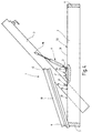
- FIG. 4 shows a further embodiment of a Roof window 1, which is different from the embodiment of Figure 1 differs in that instead of a pin 35, a sliding block 37 is provided which is along the flat top 31 of the frame 2 moves along the guideway 15, when the sash 3 is pivoted. Between the end regions 32, 33 of the guideway 15 is a height deflection 34, which is an attachment 41 is formed, that is, it will Frame 2 assigned and there for example held by screws.
- the attachment part 41 is formed such that there is a support receptacle 22nd for the support rod 21 of the spring device 17. On the structural design of the attachment part 41 is discussed in more detail below.
- Figure 5 shows the embodiment of the figure 4, the sash 3, however, in one further open position. It is recognizable that by further opening the spring device 17 no longer interacts with the frame 2, that means it no longer has any force on it Casement 3 off.
- the one forming the guide element 14 Sliding block 37 has left of it of the attachment part 41 lying on the right side of the attachment part 41 moves that means he has passed through the attachment part 41. On that is also discussed in more detail below.
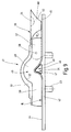
- FIG. 6 shows the attachment part 41, the one Base plate 42 has on its underside Positioning pin 43 has.
- the frame 2 assembled state grab both the base plate 42 and the positioning pin 43 in the frame 2 such that the top 31 of the Frame 2 with the areas that are level 44 and 45 of the top of the base plate 2 are aligned.
- the regions 44 and 45 thus form sections of the Guideway 15. Between areas 44 and 45 there is a height deflection 34 by an elevation 46 is formed and also the guideway 15 listened.
- the survey is asymmetrical trained, that is, she owns the area 44 associated edge 47, which is steeper than that flank 48 assigned to area 45.
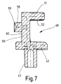
- the guideway 15 is in the region of the elevation 46 as a height deflection channel 49 trained, that is from the Base plate 42 goes - according to Figure 7- a side wall 50 from which a leg 51 extends, a Part of the base plate 42, the side wall 50 and the Leg 51 form a U-profile, in the interior the height deflection channel 49 is formed.
- the Inside 52 of leg 51 is the height contour the guideway 15 in the region of the elevation 46 accordingly adjusted so that an exact guidance of the Guide element 14 within the height deflection channel 49 takes place. Because the sliding block 37 when retracting in the height deflection channel 49 against the Flank 47 of the elevation 46 occurs, there is a fixation the corresponding angular position of the casement 3.
- Figure 8 shows a further embodiment a top section provided with a height deflection 34 41, which is compared to the embodiment of Figure 6 essentially differs in that no survey is planned, but a deepening 55, that is, when passing through the height deflection channel 49 enters the guide element 14 in the Well 55 and fixed in this way and Way the position of the casement 3.
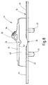
- FIG 9 shows an embodiment of a Height deflection 34 provided attachment part 41, the corresponds to the embodiment of Figure 6, however additionally a flap-like swivel Passing element 56 has.
- Passing element 56 has a side to the height deflection channel 49 located bearing leg 57 on an axis 58 rotatable on a pin 59 on the back 60 the side wall 50 is mounted (the pin 59 goes from Figure 7).
- the height diversion channel 49 a one arranged on the bearing leg 57 is sufficient
- the bevel on both sides 61 and 62 has to the guide member 14 to let pass, that means: hits the guide element 14 on the bevel 61 or 62, the passing element 56 pivots about the axis 58 upwards so that the guide element 14 pass can.
- the support receptacle 54 for the spring device 17 is arranged, the guide element 14 pass the attachment part 41 even if the spring device 17 is still in the support receptacle 54 supports.
Landscapes
- Engineering & Computer Science (AREA)
- Mechanical Engineering (AREA)
- Architecture (AREA)
- Civil Engineering (AREA)
- Structural Engineering (AREA)
- Wing Frames And Configurations (AREA)
- Closing And Opening Devices For Wings, And Checks For Wings (AREA)
- Hinges (AREA)
- Organic Low-Molecular-Weight Compounds And Preparation Thereof (AREA)
- Hydrogenated Pyridines (AREA)
Abstract
Description
- Figur 1
- eine schematische Seitenansicht eines Dachfensters in Anfangsöffnungsschwingstellung,
- Figur 2
- eine Detailansicht eines Führungselements, daß sich entlang einer Führungsbahn auf der Oberfläche eines Blendrahmens des Wohndachfensters bewegt,
- Figur 3
- eine der Figur 2 entsprechende Darstellung, jedoch mit einem andersartig gestalteten Führungselement,
- Figur 4
- eine schematische Seitenansicht eines weiteren Ausführungsbeispiels eines Dachfensters, ebenfalls in Anfangsschwingöffnungsstellung,
- Figur 5
- eine der Figur 4 entsprechende Darstellung, jedoch bei weiter geöffnetem Fenster,
- Figur 6
- eine Höhenumlenkung, die als Aufsatzteil ausgebildet ist und zur Aufnahme des Führungselements dient,
- Figur 7
- eine Schnittansicht durch die Höhenumlenkung der Figur 6,
- Figur 8
- eine Höhenumlenkung nach einem anderen Ausführungsbeispiel und
- Figur 9
- ein weiteres Ausführungsbeispiel einer Höhenumlenkung.
Claims (12)
- Dachfenster, insbesonder Schwingflügel-Dachfenster, mit einem Blendrahmen und einem Flügelrahmen, der mittels gelenkig an ihm angeordneten Hilfsrahmenprofilen um eine Schwingachse schwenkbeweglich gelagert ist, wobei die Schwingachse horizontal verläuft und sich etwa im mittigen Bereich am Flügelrahmen befindet und mit einem, mindestens an einem der Längsholme des Flügelrahmens angeordneten Führungselement, das sich beim Schwingöffnen des Flügelrahmens entlang einer am Blendrahmen ausgebildeten Führungsbahn bewegt, die in bezug zur Ebene der Oberseite des Blendrahmens auf unterschiedlichen Höhenniveaus liegt, dadurch gekennzeichnet, daß die Führungsbahn (15) zwischen ihren beiden Endbereichen (32,33) mindestens eine den Flügelrahmen (3) in gewünschter Schwingöffnungsstellung haltende Höhenumlenkung (34) für das Führungselement (14) aufweist.
- Dachfenster nach Anspruch 1, dadurch gekennzeichnet, daß die Höhenumlenkung (34) eine zur Ebene (30) der Oberseite (31) des Blendrahmens (2) konvexe Gestalt aufweist.
- Dachfenster nach einem der vorhergehenden Ansprüche, dadurch gekennzeichnet, daß die Höhenumlenkung (34) eine die Ebene (30) der Oberseite (31) des Blendrahmens (2) überragende Erhebung (46) ist.
- Dachfenster nach einen der vorhergehenden Ansprüche, dadurch gekennzeichnet, daß die Höhenumlenkung (34) eine zur Ebene (30) der Oberseite (31) des Blendrahmens (2) konkave Gestalt aufweist.
- Dachfenster nach einem der vorhergehenden Ansprüche, dadurch gekennzeichnet, daß die Höhenumlenkung (34) eine in die Ebene (30) der Oberseite (31) des Blendrahmens (2) hineinragende Vertiefung (55) ist.
- Dachfenster nach einem der vorhergehenden Ansprüche, dadurch gekennzeichnet, daß der Steigungswinkel auf der Seite der konvexen Gestalt oder Erhebung (46), gegen die das Führungselement (14) beim Schwingöffnen des Flügelrahmens (3) anläuft, größer ist als auf der Seite der konvexen Gestalt beziehungsweise Erhebung (46), gegen die das Führungselement (14) beim Schließen des Flügelrahmens (3) anläuft.
- Dachfenster nach einem der vorhergehenden Ansprüche, dadurch gekennzeichnet, daß die Höhenumlenkung (34) als dem Blendrahmen (2) zuordenbares/zugeordnetes Aufsatzteil (41) ausgebildet ist.
- Dachfenster nach einem der vorhergehenden Ansprüche, dadurch gekennzeichnet, daß das Aufsatzteil (41) eine Abstützaufnahme (22,54) für eine, eine Schwinghilfe bildende Federvorrichtung (17) aufweist.
- Dachfenster nach einem der vorhergehenden Ansprüche, dadurch gekennzeichnet, daß das Führungselement (14) einen kreisförmigen oder nicht kreisförmigen Querschnitt aufweist.
- Dachfenster nach einem der vorhergehenden Ansprüche, dadurch gekennzeichnet, daß das Führungselement (14), insbesondere im Falle seines nicht kreisförmigen Querschnitts, beim Durchlaufen der Höhenumlenkung (34) eine Schwenkbewegung um seine Längsachse durchführt.
- Dachfenster nach einem der vorhergehenden Ansprüche, dadurch gekennzeichnet, daß die Höhenumlenkung (34) als insbesondere dreiseitig geschlossener Höhenumlenkungskanal (49) ausgebildet ist.
- Dachfenster nach einem der vorhergehenden Ansprüche, dadurch gekennzeichnet, daß die Höhenumlenkung (34) etwa im oberen Drittel, im mittigen Bereich oder im unteren Drittel bezüglich der Längserstreckung der Führungsbahn (15) liegt.
Priority Applications (1)
| Application Number | Priority Date | Filing Date | Title |
|---|---|---|---|
| DK99112507T DK0972885T3 (da) | 1998-07-17 | 1999-07-01 | Svingeflöjs-tagvindue |
Applications Claiming Priority (2)
| Application Number | Priority Date | Filing Date | Title |
|---|---|---|---|
| DE19832262 | 1998-07-17 | ||
| DE19832262A DE19832262A1 (de) | 1998-07-17 | 1998-07-17 | Schwingflügel-Dachfenster |
Publications (2)
| Publication Number | Publication Date |
|---|---|
| EP0972885A1 true EP0972885A1 (de) | 2000-01-19 |
| EP0972885B1 EP0972885B1 (de) | 2004-09-15 |
Family
ID=7874462
Family Applications (1)
| Application Number | Title | Priority Date | Filing Date |
|---|---|---|---|
| EP99112507A Expired - Lifetime EP0972885B1 (de) | 1998-07-17 | 1999-07-01 | Schwingflügel-Dachfenster |
Country Status (4)
| Country | Link |
|---|---|
| EP (1) | EP0972885B1 (de) |
| AT (1) | ATE276411T1 (de) |
| DE (2) | DE19832262A1 (de) |
| DK (1) | DK0972885T3 (de) |
Cited By (7)
| Publication number | Priority date | Publication date | Assignee | Title |
|---|---|---|---|---|
| EP1355017A3 (de) * | 2002-04-17 | 2005-02-02 | Roto Frank Ag | Als Schwingfenster ausgebildetes Schrägdachfenster |
| EP1703038A3 (de) * | 2005-02-23 | 2008-06-11 | Accuride International Limited | Dachentüfter |
| EP2280143A2 (de) | 2003-08-20 | 2011-02-02 | VKR Holding A/S | Gelenkbeschlag für ein Drehfenster |
| CN103590543A (zh) * | 2013-11-01 | 2014-02-19 | 安徽工贸职业技术学院 | 一种开启式灵活的屋顶窗 |
| CN103590542A (zh) * | 2013-11-01 | 2014-02-19 | 安徽工贸职业技术学院 | 一种屋顶窗结构 |
| EP2821575A2 (de) | 2003-08-20 | 2015-01-07 | VKR Holding A/S | Verbessertes Schwenkfenster mit mindestens einer Hilfsvorrichtung zum Öffnen und einem Feststeller |
| EP2525013A3 (de) * | 2011-05-14 | 2015-08-12 | Roto Frank AG | Halteeinrichtung für ein Wohndachfenster sowie Wohndachfenster mit Halteeinrichting |
Families Citing this family (2)
| Publication number | Priority date | Publication date | Assignee | Title |
|---|---|---|---|---|
| CN1975085B (zh) * | 2006-10-13 | 2010-09-15 | 江苏大学 | 单自由度平面六杆开窗机构 |
| EP4650544A1 (de) * | 2024-05-17 | 2025-11-19 | VKR Holding A/S | Dachfenster mit kipp- und drehmechanismus und einem aktuator |
Citations (5)
| Publication number | Priority date | Publication date | Assignee | Title |
|---|---|---|---|---|
| US2080868A (en) * | 1935-11-25 | 1937-05-18 | Mayes Jess | Window sash |
| US2086043A (en) * | 1936-08-17 | 1937-07-06 | Vento Steel Sash Co Inc | Window construction |
| US2648878A (en) * | 1947-01-06 | 1953-08-18 | Albano Edmond | Completely reversible window |
| US4055024A (en) * | 1975-05-03 | 1977-10-25 | Wilh. Frank Gmbh | Roof window arrangement |
| EP0846815A2 (de) * | 1996-12-04 | 1998-06-10 | ROTO FRANK Aktiengesellschaft | Dachfenster, insbesondere Schwingflügel-Dachfenster |
Family Cites Families (2)
| Publication number | Priority date | Publication date | Assignee | Title |
|---|---|---|---|---|
| DE2631453C2 (de) * | 1976-07-13 | 1989-08-31 | Hans 7031 Steinenbronn Vollmer | Beschlag für Dachfenster |
| DE19717070C1 (de) * | 1997-04-23 | 1998-11-12 | Roto Frank Ag | Dachfenster, insbesondere Schwingflügel-Dachfenster |
-
1998
- 1998-07-17 DE DE19832262A patent/DE19832262A1/de not_active Withdrawn
-
1999
- 1999-07-01 AT AT99112507T patent/ATE276411T1/de active
- 1999-07-01 DK DK99112507T patent/DK0972885T3/da active
- 1999-07-01 DE DE59910492T patent/DE59910492D1/de not_active Expired - Lifetime
- 1999-07-01 EP EP99112507A patent/EP0972885B1/de not_active Expired - Lifetime
Patent Citations (5)
| Publication number | Priority date | Publication date | Assignee | Title |
|---|---|---|---|---|
| US2080868A (en) * | 1935-11-25 | 1937-05-18 | Mayes Jess | Window sash |
| US2086043A (en) * | 1936-08-17 | 1937-07-06 | Vento Steel Sash Co Inc | Window construction |
| US2648878A (en) * | 1947-01-06 | 1953-08-18 | Albano Edmond | Completely reversible window |
| US4055024A (en) * | 1975-05-03 | 1977-10-25 | Wilh. Frank Gmbh | Roof window arrangement |
| EP0846815A2 (de) * | 1996-12-04 | 1998-06-10 | ROTO FRANK Aktiengesellschaft | Dachfenster, insbesondere Schwingflügel-Dachfenster |
Cited By (9)
| Publication number | Priority date | Publication date | Assignee | Title |
|---|---|---|---|---|
| EP1355017A3 (de) * | 2002-04-17 | 2005-02-02 | Roto Frank Ag | Als Schwingfenster ausgebildetes Schrägdachfenster |
| CZ304260B6 (cs) * | 2002-04-17 | 2014-02-05 | Roto Frank Ag | Střešní okno v šikmé střeše, vytvořené jako kyvné okno |
| EP2280143A2 (de) | 2003-08-20 | 2011-02-02 | VKR Holding A/S | Gelenkbeschlag für ein Drehfenster |
| EP2821575A2 (de) | 2003-08-20 | 2015-01-07 | VKR Holding A/S | Verbessertes Schwenkfenster mit mindestens einer Hilfsvorrichtung zum Öffnen und einem Feststeller |
| EP2821575A3 (de) * | 2003-08-20 | 2015-03-04 | VKR Holding A/S | Verbessertes Schwenkfenster mit mindestens einer Hilfsvorrichtung zum Öffnen und einem Feststeller |
| EP1703038A3 (de) * | 2005-02-23 | 2008-06-11 | Accuride International Limited | Dachentüfter |
| EP2525013A3 (de) * | 2011-05-14 | 2015-08-12 | Roto Frank AG | Halteeinrichtung für ein Wohndachfenster sowie Wohndachfenster mit Halteeinrichting |
| CN103590543A (zh) * | 2013-11-01 | 2014-02-19 | 安徽工贸职业技术学院 | 一种开启式灵活的屋顶窗 |
| CN103590542A (zh) * | 2013-11-01 | 2014-02-19 | 安徽工贸职业技术学院 | 一种屋顶窗结构 |
Also Published As
| Publication number | Publication date |
|---|---|
| ATE276411T1 (de) | 2004-10-15 |
| EP0972885B1 (de) | 2004-09-15 |
| DE19832262A1 (de) | 2000-01-20 |
| DK0972885T3 (da) | 2004-12-06 |
| DE59910492D1 (de) | 2004-10-21 |
Similar Documents
| Publication | Publication Date | Title |
|---|---|---|
| EP0687787B1 (de) | Scharniereinrichtung | |
| EP0679775B1 (de) | Klapp-Schwing-Dachfenster mit Ausstellhilfe | |
| DE2648344A1 (de) | Beschlag fuer schiebefenster, schiebetueren u.dgl. | |
| EP0972885B1 (de) | Schwingflügel-Dachfenster | |
| EP0201717B1 (de) | Beschlag für einen zumindest parallelabstellbaren und verschiebbaren Flügel eines Fensters, eine Tür oder dergleichen | |
| EP1017920B1 (de) | Beschlag zur drehlagerung eines fenster- oder türflügels | |
| EP0438740A1 (de) | Beschlag für einen wenigstens drehbaren Flügel eines Fensters, einer Tür od.dgl. | |
| EP0096744A2 (de) | Drehkippbeschlag | |
| EP0851085A1 (de) | Drehkippbeschlag mit unverschieblichem Ecklagerpunkt | |
| EP3749822B1 (de) | Unterstützungsbeschlag für einen kippbaren flügel eines fensters oder einer tür | |
| EP0874102B1 (de) | Dachfenster, insbesondere Schwingflügel-Dachfenster | |
| EP0846815B1 (de) | Dachfenster, insbesondere Schwingflügel-Dachfenster | |
| EP0874123B1 (de) | Beschlag zur Lagerung des Drehflügels eines Fensters oder einer Tür | |
| DE19600948C1 (de) | Einrichtung zum Gewichtsausgleich eines Dachfensters | |
| DE8103368U1 (de) | Drehkippfenster oder -tür | |
| EP1581712B1 (de) | Beschlageinheit für ein fenster oder eine tür | |
| DE2658463A1 (de) | Dach-wohnraumfenster | |
| DE4422213C2 (de) | Drehkippbeschlag | |
| DE3203321A1 (de) | Fluegelrahmenseitiges ecklager fuer fenster, insbesondere drehkippfenster | |
| DE3911187A1 (de) | Hebekippfenster | |
| CH655970A5 (en) | Dormer window | |
| DE1930485A1 (de) | Schwenkschiebetuer,insbesondere fuer Strassen- und Schienenfahrzeuge | |
| DE19825071A1 (de) | Parallelausstellfenster mit Drehfunktion | |
| DE3324299A1 (de) | Schiebe-schwenktuer | |
| DE9116309U1 (de) | Beschlag für kipp- und parallel abstellbare Schiebeflügel |
Legal Events
| Date | Code | Title | Description |
|---|---|---|---|
| PUAI | Public reference made under article 153(3) epc to a published international application that has entered the european phase |
Free format text: ORIGINAL CODE: 0009012 |
|
| AK | Designated contracting states |
Kind code of ref document: A1 Designated state(s): AT CH DE DK FR GB LI |
|
| AX | Request for extension of the european patent |
Free format text: AL;LT;LV;MK;RO;SI |
|
| 17P | Request for examination filed |
Effective date: 20000704 |
|
| AKX | Designation fees paid |
Free format text: AT CH DE DK FR GB LI |
|
| 17Q | First examination report despatched |
Effective date: 20030416 |
|
| GRAP | Despatch of communication of intention to grant a patent |
Free format text: ORIGINAL CODE: EPIDOSNIGR1 |
|
| GRAS | Grant fee paid |
Free format text: ORIGINAL CODE: EPIDOSNIGR3 |
|
| GRAA | (expected) grant |
Free format text: ORIGINAL CODE: 0009210 |
|
| AK | Designated contracting states |
Kind code of ref document: B1 Designated state(s): AT CH DE DK FR GB LI |
|
| REG | Reference to a national code |
Ref country code: GB Ref legal event code: FG4D Free format text: NOT ENGLISH Ref country code: CH Ref legal event code: EP |
|
| REF | Corresponds to: |
Ref document number: 59910492 Country of ref document: DE Date of ref document: 20041021 Kind code of ref document: P |
|
| REG | Reference to a national code |
Ref country code: CH Ref legal event code: NV Representative=s name: E. BLUM & CO. PATENTANWAELTE |
|
| REG | Reference to a national code |
Ref country code: DK Ref legal event code: T3 |
|
| GBT | Gb: translation of ep patent filed (gb section 77(6)(a)/1977) |
Effective date: 20050110 |
|
| ET | Fr: translation filed | ||
| PLBE | No opposition filed within time limit |
Free format text: ORIGINAL CODE: 0009261 |
|
| STAA | Information on the status of an ep patent application or granted ep patent |
Free format text: STATUS: NO OPPOSITION FILED WITHIN TIME LIMIT |
|
| 26N | No opposition filed |
Effective date: 20050616 |
|
| REG | Reference to a national code |
Ref country code: CH Ref legal event code: PFA Owner name: ROTO FRANK AG Free format text: ROTO FRANK AG#STUTTGARTER STRASSE 145-149#70771 LEINFELDEN-ECHTERDINGEN (DE) -TRANSFER TO- ROTO FRANK AG#STUTTGARTER STRASSE 145-149#70771 LEINFELDEN-ECHTERDINGEN (DE) |
|
| PGFP | Annual fee paid to national office [announced via postgrant information from national office to epo] |
Ref country code: GB Payment date: 20110620 Year of fee payment: 13 |
|
| PGFP | Annual fee paid to national office [announced via postgrant information from national office to epo] |
Ref country code: DK Payment date: 20110704 Year of fee payment: 13 |
|
| GBPC | Gb: european patent ceased through non-payment of renewal fee |
Effective date: 20120701 |
|
| PG25 | Lapsed in a contracting state [announced via postgrant information from national office to epo] |
Ref country code: GB Free format text: LAPSE BECAUSE OF NON-PAYMENT OF DUE FEES Effective date: 20120701 |
|
| REG | Reference to a national code |
Ref country code: DK Ref legal event code: EBP Effective date: 20130731 |
|
| PG25 | Lapsed in a contracting state [announced via postgrant information from national office to epo] |
Ref country code: DK Free format text: LAPSE BECAUSE OF NON-PAYMENT OF DUE FEES Effective date: 20130731 |
|
| PGFP | Annual fee paid to national office [announced via postgrant information from national office to epo] |
Ref country code: CH Payment date: 20140722 Year of fee payment: 16 |
|
| PGFP | Annual fee paid to national office [announced via postgrant information from national office to epo] |
Ref country code: AT Payment date: 20140620 Year of fee payment: 16 |
|
| REG | Reference to a national code |
Ref country code: CH Ref legal event code: PL |
|
| REG | Reference to a national code |
Ref country code: AT Ref legal event code: MM01 Ref document number: 276411 Country of ref document: AT Kind code of ref document: T Effective date: 20150701 |
|
| PG25 | Lapsed in a contracting state [announced via postgrant information from national office to epo] |
Ref country code: LI Free format text: LAPSE BECAUSE OF NON-PAYMENT OF DUE FEES Effective date: 20150731 Ref country code: CH Free format text: LAPSE BECAUSE OF NON-PAYMENT OF DUE FEES Effective date: 20150731 |
|
| PG25 | Lapsed in a contracting state [announced via postgrant information from national office to epo] |
Ref country code: AT Free format text: LAPSE BECAUSE OF NON-PAYMENT OF DUE FEES Effective date: 20150701 |
|
| REG | Reference to a national code |
Ref country code: FR Ref legal event code: PLFP Year of fee payment: 18 |
|
| PGFP | Annual fee paid to national office [announced via postgrant information from national office to epo] |
Ref country code: DE Payment date: 20160721 Year of fee payment: 18 |
|
| PGFP | Annual fee paid to national office [announced via postgrant information from national office to epo] |
Ref country code: FR Payment date: 20160722 Year of fee payment: 18 |
|
| REG | Reference to a national code |
Ref country code: DE Ref legal event code: R119 Ref document number: 59910492 Country of ref document: DE |
|
| REG | Reference to a national code |
Ref country code: FR Ref legal event code: ST Effective date: 20180330 |
|
| PG25 | Lapsed in a contracting state [announced via postgrant information from national office to epo] |
Ref country code: DE Free format text: LAPSE BECAUSE OF NON-PAYMENT OF DUE FEES Effective date: 20180201 |
|
| PG25 | Lapsed in a contracting state [announced via postgrant information from national office to epo] |
Ref country code: FR Free format text: LAPSE BECAUSE OF NON-PAYMENT OF DUE FEES Effective date: 20170731 |