EP0972900B1 - Crémone-serrure - Google Patents
Crémone-serrure Download PDFInfo
- Publication number
- EP0972900B1 EP0972900B1 EP99109009A EP99109009A EP0972900B1 EP 0972900 B1 EP0972900 B1 EP 0972900B1 EP 99109009 A EP99109009 A EP 99109009A EP 99109009 A EP99109009 A EP 99109009A EP 0972900 B1 EP0972900 B1 EP 0972900B1
- Authority
- EP
- European Patent Office
- Prior art keywords
- nut
- latch
- arm
- espagnolette
- espagnolette lock
- Prior art date
- Legal status (The legal status is an assumption and is not a legal conclusion. Google has not performed a legal analysis and makes no representation as to the accuracy of the status listed.)
- Expired - Lifetime
Links
Images




Classifications
-
- E—FIXED CONSTRUCTIONS
- E05—LOCKS; KEYS; WINDOW OR DOOR FITTINGS; SAFES
- E05C—BOLTS OR FASTENING DEVICES FOR WINGS, SPECIALLY FOR DOORS OR WINDOWS
- E05C9/00—Arrangements of simultaneously actuated bolts or other securing devices at well-separated positions on the same wing
- E05C9/02—Arrangements of simultaneously actuated bolts or other securing devices at well-separated positions on the same wing with one sliding bar for fastening when moved in one direction and unfastening when moved in opposite direction; with two sliding bars moved in the same direction when fastening or unfastening
- E05C9/021—Arrangements of simultaneously actuated bolts or other securing devices at well-separated positions on the same wing with one sliding bar for fastening when moved in one direction and unfastening when moved in opposite direction; with two sliding bars moved in the same direction when fastening or unfastening with rack and pinion mechanism
- E05C9/023—Arrangements of simultaneously actuated bolts or other securing devices at well-separated positions on the same wing with one sliding bar for fastening when moved in one direction and unfastening when moved in opposite direction; with two sliding bars moved in the same direction when fastening or unfastening with rack and pinion mechanism between a lock cylinder and the bar
-
- E—FIXED CONSTRUCTIONS
- E05—LOCKS; KEYS; WINDOW OR DOOR FITTINGS; SAFES
- E05B—LOCKS; ACCESSORIES THEREFOR; HANDCUFFS
- E05B59/00—Locks with latches separate from the lock-bolts or with a plurality of latches or lock-bolts
-
- E—FIXED CONSTRUCTIONS
- E05—LOCKS; KEYS; WINDOW OR DOOR FITTINGS; SAFES
- E05B—LOCKS; ACCESSORIES THEREFOR; HANDCUFFS
- E05B65/00—Locks or fastenings for special use
- E05B65/10—Locks or fastenings for special use for panic or emergency doors
- E05B65/1086—Locks with panic function, e.g. allowing opening from the inside without a ley even when locked from the outside
-
- E—FIXED CONSTRUCTIONS
- E05—LOCKS; KEYS; WINDOW OR DOOR FITTINGS; SAFES
- E05B—LOCKS; ACCESSORIES THEREFOR; HANDCUFFS
- E05B63/00—Locks or fastenings with special structural characteristics
- E05B63/16—Locks or fastenings with special structural characteristics with the handles on opposite sides moving independently
Definitions
- the invention relates to a drive rod lock according to the preamble of claim 1.
- Such a closure is known from the EP 0 834 633 A1 , wherein the latch tail is designed in two parts.
- the front part of the latch tail carries the case head, while the rear part is coupled via a pivot pin with the return lever. At the rear part then attacks the Nussarm the pusher.
- the pivot axis for the pull-back lever between the case head and nut extends, so that particularly small backset dimensions are not feasible.
- the EP 0 091517 describes a similar closure. Again, the case can be dragged back both by handle operation as well as by alternating operation. Again, a change lever is provided, the pivot bearing is located behind and below the nut.
- espagnolette lock of the type in question is of simple construction realized.
- the latch tail can now be designed in one piece as a result of the rear lever mounted on the return lever.
- a reduction of the backset to 35 mm and smaller is possible.
- the espagnolette lock can also be best associated with tubular frame doors. Nevertheless, there are no disadvantages in terms of panic function, so the vortexen bolt, and the upstream espagnolette slide the default case retreat from the inside of the door by means of the pusher.
- the per se proven design of a generic espagnolette closure can be largely maintained, since the housing cover and housing bottom form a recess lying above the nut axis, in which a retainer lever bearing housing extension is arranged.
- the bulge is such that the extension is aligned with the Sch throughge Reifenückkante, so that there are no disadvantages in terms of installation depth.
- a drive arm of the retraction lever can be acted upon by a Nußarm.
- the Nußarm acts directly on the return lever, which allows a favorable force application to the espagnolette gate valve by means of the retracting lever.
- the drive arm pivots in the closing movement of the Nußarmes when Sch thoroughlyzylinderbetätigten locking latch. In a panic situation, accordingly, the immediate entrainment of the retraction lever takes place, which in turn acts on the espagnolette slide in conjunction with the handle shift.
- the embodiment of the invention allows the realization of a drive rod closure with split nut.
- the corresponding two-parted nut points an inner and outer half of the nut, wherein the outer half of the nut acts only on the latch tail and actuates both trap and retraction lever in the inner half of the nut.
- the required unilateral clearance between the two nut halves is easier. Way created by the inner half of the nut associated Nußarm entrained the outer half of the nut associated Nußarm during its pivoting.
- the invention provides that the angular retraction lever is curved sickle-shaped and rests with its sickle cavity in its caused by the pusher groove open position of the espagnolette corresponding position on a sleeve of a fitting screw passage opening. As a result, the return lever undergoes a support.
- a further advantageous feature is the fact that the output arm in its position corresponding to the open position of the espagnolette closure partially overlaps the latch tail when the latch is retracted. So there is a nesting instead, which allows the construction of a crowded castle.
- the output arm engages in a recess of a vertical portion of the drive rod terminal slide. This intervention is not given up in the locked or withdrawn latch, so that always the proper closing function is guaranteed.
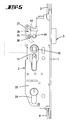
- a case 5 is guided. Its case head 6 is connected to a latch tail 7. End this forms a driving projection 8 from the attack of a Nußarmes 9 a pusher 10.
- the pusher 10 is designed in one piece.
- the pusher 10 is provided with a further Nußarm 11, which via a parallel to the forend 1 extending spring slide 12 counterclockwise is charged.
- the spring slide 12 is under the action of a compression spring 13.
- the nut 10 including the spring slide 12 and compression spring 13 are received by a mountable in the espagnolette nut bearing housing 14.
- the latter also includes an unillustrated stop, which serves as a stop limit for the nut 10 in its normal position.
- the lock bottom 20 and arranged parallel to her lock cover 21 carry between them a support plate T. These stored in its lower part in a lock cover 21 facing bore 22 a ring gear 23. A lock cylinder insertion opening 24 crosses this hole.
- the axis of rotation of the cylinder core not shown is eccentric to the axis of rotation of the ring gear 23, below it.
- the espagnolette 31 controls the interposition of a pivot lever 34, the bolt exclusion in such a way that initially the espagnolette connector 31 precedes the bolt exclusion and then the entrainment of the bolt 18 takes place.
- the first drive rod-side locking members can first attack and cause the door to tighten, so that then the latch 21 can enter into the associated SchröblechausEnglishung without hindrance.
- This is from the EP 0 834 633 A1 known, so that it is not discussed further.
- This also applies to the changeover operation, with the lower drive rod connection slide not illustrated Interchangeable lever acted which in turn pulls the latch 5 lock inward.
- the pivot axis 35 is formed by a housing extension 37, for which the housing bottom 20 and the housing cover form an aligned, above the nut axis lying bulge 38, see. especially Fig. 5 .
- the downwardly and in the direction of the nut 10 facing drive arm 39 of the retraction lever is positioned so that it can be acted upon by the Nußarm 9.
- bar lock cf. Fig. 2
- the drive arm 39 is pivoted into the path of movement of the Nußarmes 9, see. Fig. 2
- the drive arm 39 partially overlaps the bolt tail 7 or its driving projection 8.
- the angle-shaped retraction lever 36 otherwise has a sickle-shaped curvature.
- the sickle cavity 42 formed by the output arm 41 is located in the open position of the espagnolette closure caused by the presser foot 10 on a sleeve 43 of a fitting screw passage opening 44, cf. Fig. 4 ,
- the sleeve 43 is also part of the housing extension 37. Also leaves Fig. 4 recognize that the output arm 41 partially overlaps the latch tail 7 in its position corresponding to the open position of the espagnolette when the latch 5 is retracted.
- a recess 40 To attack the Abretesarmes 41 forms an upper vertical portion of the espagnolette gate valve 31 a recess 40, in which the free end of Abtriebarmes 41 dips.
- the so-designed espagnolette lock allows to realize a backset which is equal to or smaller than 35 mm.
- the door handle 46 is to depress and thus to pivot the pusher 10.
- Their Nußarm 9 acts on the driving projection 8 of the latch tail 7 connected to the fact that the case 5 is pulled in Sch providedeingnocardi.
- the nut arm 9 also urges the drive arm 39 of the retraction lever 36, the output arm 41 of which engages in the recess 40 moves the drive rod connection slide 31 in the downward direction.
- the other gears of the reduction gear G are rotated and thus also the output gears 27, 28 which rotate the ring gear 23.
- the pusher nut 47 is now divided into two parts in such a way that the dividing plane runs parallel to the lock cover and lock bottom.
- the pusher nut 47 is composed of an inner half nut 48 and an outer half half 49 of the nut. Both nut halves 48, 49 are each equipped with a Nußarm 50 for attacking the spring slider 12.
- the outer Nußhdon 49 then has a further Nußarm 51, which extends outside the trajectory of the drive arm 39 in another plane and only on the Fallen tail 7 and whose driving projection 8 acts.
- the inner half nut 48 forms a Nußarm 52, which actuates both the latch 5 and the retraction lever 36.
- the nut arm 52 assigned to the inner half of the nut 48 tows the nut arm 51 associated with the outer half of the nut 49 during its pivoting, thereby realizing a unilateral clearance.
- the in the FIGS. 10 to 13 illustrated third embodiment is similar to the above. Again, it is true that the same components carry the same reference numerals.
- the pusher nut 47 ' is also divided into two, consisting of the outer half of the nut 48' and the inner half of the nut 49 '.
- the latter is equipped with an inwardly projecting collar 53 'which dips into a bearing cavity 54' of the outer half nut 48 '.
- the mode of action corresponds to the preceding one.
- the outer half of the nut 48 'in the position according to Fig. 11 pivoted, with one of the Nußarm 52 'pulls the lock 5 lock inwards and the other Nußarm 50' displaces the spring slide 12.
- the door inner handle If the door inner handle is in accordance with Fig. 12 actuated, it pivots the inside of the door nut half 49 ', which carries on its Nußarm 51', the outer Nußhcut 89 'according to the one-sided clearance.
- the outer half of the nut 48 ' pulls back on its Nußarm 52' the case 5, wherein the Nußarm 52 'also acts on the retraction lever 36.
Landscapes
- Engineering & Computer Science (AREA)
- Mechanical Engineering (AREA)
- Business, Economics & Management (AREA)
- Emergency Management (AREA)
- Lock And Its Accessories (AREA)
Claims (9)
- Serrure à barres mobiles, avec un pêne demi-tour (5), rétractable par actionnement d'une poignée, et avec un verrou (18), déplaçable par actionnement d'un cylindre de fermeture, et un coulisseau de raccordement de barres mobiles (31) et avec un levier de rétraction (36) à forme coudée, agissant sur le coulisseau de raccordement de barres mobiles (31), susceptible de pivoter par actionnement d'une poignée, pour rétracter le coulisseau de raccordement de barres mobiles (31) et le verrou (18), caractérisée en ce que l'axe de pivotement (35) du levier de rétraction (36) est disposé fixe par rapport au boîtier, à l'arrière du fouillot de poignée (10, 47, 47'), et un bras d'entraînement (39) du levier de rétraction (36) est susceptible d'être sollicité par une bras de fouillot (9) du fouillot de poignée.
- Serrure à barres mobiles selon la revendication 1, caractérisée en ce que le couvercle de boîtier et le fond de boîtier (20) constituent une échancrure (38) située au-dessus de l'axe de fouillot, dans laquelle est disposé un prolongement de boîtier (37) servant au montage en palier du levier de rétraction (36).
- Serrure à barres mobiles selon l'une des revendications précédentes, caractérisée en ce que le bras d'entraînement (39) pivote dans la trajectoire de déplacement du bras de fouillot (9) lors de la préfermeture de verrou actionnée par le cylindre de fermeture.
- Serrure à barres mobiles selon la revendication 3, caractérisée en ce que le bras d'entraînement (39) chevauche partiellement la queue de pêne demi-tour (7) lorsque l'on se trouve à la position de verrou préfermée.
- Serrure à barres mobiles selon l'une des revendications précédentes, caractérisée en ce que le fouillot (47, 47') est divisé en deux, avec une moitié de fouillot intérieure et une moitié de fouillot extérieure (48, 49', 49, 48'), la moitié de fouillot extérieure (49, 48') n'agissant que sur la queue de pêne demi-tour (7) et la moitié de fouillot intérieure (48, 49') actionnant tant le pêne demi-tour (5) qu'également le levier de rétraction (36).
- Serrure à barres mobiles selon la revendication 5, caractérisée en ce que le bras de fouillot (52, 51'), associé à la moitié de fouillot intérieure (48, 49'), lors de son pivotement, entraîne le bras de fouillot (51, 52') associé à la moitié de fouillot extérieure (49, 48').
- Serrure à barres mobiles selon l'une des revendications précédentes, caractérisée en ce que le levier de rétraction (36) coudé est incurvé en croissant, et, avec sa cavité de croissant (42), dans sa position, correspondant à une position d'ouverture, provoquée par le fouillot de poignée (10), de la fermeture à barres mobiles, appuie sur une douille (43) d'une ouverture de passage de vis de ferrure (44).
- Serrure à barres mobiles selon l'une des revendications précédentes, caractérisée en ce qu'un bras mené (41), dans sa position, correspondant à la position d'ouverture de la fermeture à barres mobiles, chevauche partiellement la queue de pêne demi-tour (7) lorsque le pêne demi-tour (5) est rétracté.
- Serrure à barres mobiles selon la revendication 8, caractérisée en ce que le bras mené (41) s'engage dans un évidement (40) du tronçon vertical du coulisseau de raccordement de barres mobiles (31).
Applications Claiming Priority (2)
| Application Number | Priority Date | Filing Date | Title |
|---|---|---|---|
| DE19831671 | 1998-07-15 | ||
| DE19831671A DE19831671A1 (de) | 1998-07-15 | 1998-07-15 | Treibstangenverschluß |
Publications (3)
| Publication Number | Publication Date |
|---|---|
| EP0972900A2 EP0972900A2 (fr) | 2000-01-19 |
| EP0972900A3 EP0972900A3 (fr) | 2004-01-02 |
| EP0972900B1 true EP0972900B1 (fr) | 2011-06-29 |
Family
ID=7874087
Family Applications (1)
| Application Number | Title | Priority Date | Filing Date |
|---|---|---|---|
| EP99109009A Expired - Lifetime EP0972900B1 (fr) | 1998-07-15 | 1999-05-06 | Crémone-serrure |
Country Status (3)
| Country | Link |
|---|---|
| EP (1) | EP0972900B1 (fr) |
| AT (1) | ATE514829T1 (fr) |
| DE (1) | DE19831671A1 (fr) |
Cited By (1)
| Publication number | Priority date | Publication date | Assignee | Title |
|---|---|---|---|---|
| CN105971415A (zh) * | 2016-07-20 | 2016-09-28 | 皓月汽车安全系统技术股份有限公司 | 一种右中门后锁总成 |
Families Citing this family (4)
| Publication number | Priority date | Publication date | Assignee | Title |
|---|---|---|---|---|
| US7526933B2 (en) | 2006-10-18 | 2009-05-05 | Master Lock Company Llc | Multipoint door lock |
| DE202007003890U1 (de) | 2007-03-16 | 2008-07-31 | Carl Fuhr Gmbh & Co. Kg | Schloss, insbesondere Panikschloss mit Nussbetätigungsstellungssensor |
| ITBO20110625A1 (it) * | 2011-11-04 | 2013-05-05 | Cisa Spa | Serratura perfezionata con elevata versatilita' |
| ITBO20110624A1 (it) * | 2011-11-04 | 2013-05-05 | Cisa Spa | Unita' principale per serrature multipunto |
Family Cites Families (4)
| Publication number | Priority date | Publication date | Assignee | Title |
|---|---|---|---|---|
| FR2452561A1 (fr) * | 1979-03-24 | 1980-10-24 | Fliether Karl | Serrure de porte, notamment serrure a mortaise |
| DE3213454C2 (de) * | 1982-04-10 | 1985-02-14 | Carl Fuhr Gmbh & Co, 5628 Heiligenhaus | Wechselhebel-Betätigungsvorrichtung in einem zweitourigen schließzylinderbetätigbaren Treibstangenschloß |
| DE3505379C2 (de) * | 1985-02-16 | 1996-03-21 | Fliether Karl Gmbh & Co | Treibstangenschloß |
| DE19640558A1 (de) * | 1996-10-01 | 1998-04-02 | Fuhr Carl Gmbh & Co | Schließzylinderbetätigbares Treibstangenschloß |
-
1998
- 1998-07-15 DE DE19831671A patent/DE19831671A1/de not_active Withdrawn
-
1999
- 1999-05-06 AT AT99109009T patent/ATE514829T1/de active
- 1999-05-06 EP EP99109009A patent/EP0972900B1/fr not_active Expired - Lifetime
Cited By (2)
| Publication number | Priority date | Publication date | Assignee | Title |
|---|---|---|---|---|
| CN105971415A (zh) * | 2016-07-20 | 2016-09-28 | 皓月汽车安全系统技术股份有限公司 | 一种右中门后锁总成 |
| CN105971415B (zh) * | 2016-07-20 | 2018-01-12 | 皓月汽车安全系统技术股份有限公司 | 一种右中门后锁总成 |
Also Published As
| Publication number | Publication date |
|---|---|
| EP0972900A2 (fr) | 2000-01-19 |
| EP0972900A3 (fr) | 2004-01-02 |
| ATE514829T1 (de) | 2011-07-15 |
| DE19831671A1 (de) | 2000-01-20 |
Similar Documents
| Publication | Publication Date | Title |
|---|---|---|
| DE102006059568A1 (de) | Schließanlage für Türen, Fenster oder dergleichen, insbesondere Treibstangenschloss mit Panikfunktion und Mehrpunktverriegelung | |
| EP2749721B1 (fr) | Crémone espagnolette | |
| DE2914377A1 (de) | Verschluss fuer zweifluegelige tueren | |
| EP1574644A2 (fr) | Système de verrouillage pour portes, fenêtres ou similaires, notamment crémone-serrure avec fonction anti-panique et avec plusieurs points de condamnation | |
| EP1020597B1 (fr) | Serrure à crémone avec une serrure principal et une serrure complémentaire | |
| EP0954667B1 (fr) | Serrure a pene demi-tour pour porte ou fenetre | |
| DE19901661A1 (de) | Treibstangenverschluß | |
| EP2072725A2 (fr) | Crémone-serrure | |
| DE4014041A1 (de) | Schliesszylinderbetaetigbares treibstangenschloss | |
| EP0454966B1 (fr) | Serrure avec bielle motrice actionnée par cylindre de fermeture | |
| EP2072723A2 (fr) | Crémone-serrure | |
| EP0995866B1 (fr) | Serrure, notamment crémone serrure | |
| DE3213454C2 (de) | Wechselhebel-Betätigungsvorrichtung in einem zweitourigen schließzylinderbetätigbaren Treibstangenschloß | |
| DE202009016137U1 (de) | Treibstangenschloss mit Panikfunktion und Mehrfachverriegelung | |
| EP0454959B1 (fr) | Serrure de barre coulissante manoeuvrable d'un barillet | |
| DE3148030A1 (de) | Zahnradantrieb in einem schliesszylinderbetaetigbaren treibstangenschloss mit schubriegel | |
| DE69800295T2 (de) | Treibstangenbeschlag oder Treibstangenverschluß für Tür, Fenster oder dergl. | |
| EP0972900A2 (fr) | Crémone-serrure | |
| EP0454960B1 (fr) | Cremone | |
| EP0974721B1 (fr) | Serrure à plusieurs pênes | |
| EP0496076B1 (fr) | Crémone-serrure | |
| DE4014045A1 (de) | Einsteckschloss, insbesondere treibstangenschloss | |
| DE19756116B4 (de) | Treibstangenverschluß | |
| DE19640558A1 (de) | Schließzylinderbetätigbares Treibstangenschloß | |
| EP2320013B1 (fr) | Armature dotée d'une transmission de renvoi |
Legal Events
| Date | Code | Title | Description |
|---|---|---|---|
| PUAI | Public reference made under article 153(3) epc to a published international application that has entered the european phase |
Free format text: ORIGINAL CODE: 0009012 |
|
| AK | Designated contracting states |
Kind code of ref document: A2 Designated state(s): AT BE CH CY DE DK ES FI FR GB GR IE IT LI LU MC NL PT SE |
|
| AX | Request for extension of the european patent |
Free format text: AL;LT;LV;MK;RO;SI |
|
| RIC1 | Information provided on ipc code assigned before grant |
Ipc: 7E 05C 9/02 B Ipc: 7E 05B 59/00 B Ipc: 7E 05C 9/00 A |
|
| PUAL | Search report despatched |
Free format text: ORIGINAL CODE: 0009013 |
|
| AK | Designated contracting states |
Kind code of ref document: A3 Designated state(s): AT BE CH CY DE DK ES FI FR GB GR IE IT LI LU MC NL PT SE |
|
| AX | Request for extension of the european patent |
Extension state: AL LT LV MK RO SI |
|
| 17P | Request for examination filed |
Effective date: 20040503 |
|
| AKX | Designation fees paid |
Designated state(s): AT DE FR GB IT NL |
|
| 17Q | First examination report despatched |
Effective date: 20050210 |
|
| 17Q | First examination report despatched |
Effective date: 20050210 |
|
| GRAC | Information related to communication of intention to grant a patent modified |
Free format text: ORIGINAL CODE: EPIDOSCIGR1 |
|
| GRAP | Despatch of communication of intention to grant a patent |
Free format text: ORIGINAL CODE: EPIDOSNIGR1 |
|
| RAP1 | Party data changed (applicant data changed or rights of an application transferred) |
Owner name: CARL FUHR GMBH & CO. KG |
|
| GRAS | Grant fee paid |
Free format text: ORIGINAL CODE: EPIDOSNIGR3 |
|
| GRAA | (expected) grant |
Free format text: ORIGINAL CODE: 0009210 |
|
| AK | Designated contracting states |
Kind code of ref document: B1 Designated state(s): AT DE FR GB IT NL |
|
| REG | Reference to a national code |
Ref country code: GB Ref legal event code: FG4D Free format text: NOT ENGLISH |
|
| REG | Reference to a national code |
Ref country code: DE Ref legal event code: R096 Ref document number: 59915281 Country of ref document: DE Effective date: 20110818 |
|
| REG | Reference to a national code |
Ref country code: NL Ref legal event code: T3 |
|
| PLBE | No opposition filed within time limit |
Free format text: ORIGINAL CODE: 0009261 |
|
| STAA | Information on the status of an ep patent application or granted ep patent |
Free format text: STATUS: NO OPPOSITION FILED WITHIN TIME LIMIT |
|
| 26N | No opposition filed |
Effective date: 20120330 |
|
| REG | Reference to a national code |
Ref country code: DE Ref legal event code: R097 Ref document number: 59915281 Country of ref document: DE Effective date: 20120330 |
|
| REG | Reference to a national code |
Ref country code: FR Ref legal event code: PLFP Year of fee payment: 18 |
|
| REG | Reference to a national code |
Ref country code: FR Ref legal event code: PLFP Year of fee payment: 19 |
|
| PGFP | Annual fee paid to national office [announced via postgrant information from national office to epo] |
Ref country code: NL Payment date: 20170516 Year of fee payment: 19 |
|
| PGFP | Annual fee paid to national office [announced via postgrant information from national office to epo] |
Ref country code: FR Payment date: 20170519 Year of fee payment: 19 Ref country code: GB Payment date: 20170519 Year of fee payment: 19 Ref country code: DE Payment date: 20170531 Year of fee payment: 19 |
|
| PGFP | Annual fee paid to national office [announced via postgrant information from national office to epo] |
Ref country code: IT Payment date: 20170526 Year of fee payment: 19 Ref country code: AT Payment date: 20170522 Year of fee payment: 19 |
|
| REG | Reference to a national code |
Ref country code: DE Ref legal event code: R119 Ref document number: 59915281 Country of ref document: DE |
|
| REG | Reference to a national code |
Ref country code: NL Ref legal event code: MM Effective date: 20180601 |
|
| REG | Reference to a national code |
Ref country code: AT Ref legal event code: MM01 Ref document number: 514829 Country of ref document: AT Kind code of ref document: T Effective date: 20180506 |
|
| GBPC | Gb: european patent ceased through non-payment of renewal fee |
Effective date: 20180506 |
|
| PG25 | Lapsed in a contracting state [announced via postgrant information from national office to epo] |
Ref country code: AT Free format text: LAPSE BECAUSE OF NON-PAYMENT OF DUE FEES Effective date: 20180506 |
|
| PG25 | Lapsed in a contracting state [announced via postgrant information from national office to epo] |
Ref country code: FR Free format text: LAPSE BECAUSE OF NON-PAYMENT OF DUE FEES Effective date: 20180531 Ref country code: IT Free format text: LAPSE BECAUSE OF NON-PAYMENT OF DUE FEES Effective date: 20180506 Ref country code: DE Free format text: LAPSE BECAUSE OF NON-PAYMENT OF DUE FEES Effective date: 20181201 Ref country code: NL Free format text: LAPSE BECAUSE OF NON-PAYMENT OF DUE FEES Effective date: 20180601 Ref country code: GB Free format text: LAPSE BECAUSE OF NON-PAYMENT OF DUE FEES Effective date: 20180506 |