EP0972939A2 - Leistungsregelvorrichtung für mehrere Hydropumpen - Google Patents
Leistungsregelvorrichtung für mehrere Hydropumpen Download PDFInfo
- Publication number
- EP0972939A2 EP0972939A2 EP99113343A EP99113343A EP0972939A2 EP 0972939 A2 EP0972939 A2 EP 0972939A2 EP 99113343 A EP99113343 A EP 99113343A EP 99113343 A EP99113343 A EP 99113343A EP 0972939 A2 EP0972939 A2 EP 0972939A2
- Authority
- EP
- European Patent Office
- Prior art keywords
- control device
- throttle
- hydraulic pump
- valve
- power control
- Prior art date
- Legal status (The legal status is an assumption and is not a legal conclusion. Google has not performed a legal analysis and makes no representation as to the accuracy of the status listed.)
- Granted
Links
Images


Classifications
-
- F—MECHANICAL ENGINEERING; LIGHTING; HEATING; WEAPONS; BLASTING
- F04—POSITIVE - DISPLACEMENT MACHINES FOR LIQUIDS; PUMPS FOR LIQUIDS OR ELASTIC FLUIDS
- F04B—POSITIVE-DISPLACEMENT MACHINES FOR LIQUIDS; PUMPS
- F04B49/00—Control, e.g. of pump delivery, or pump pressure of, or safety measures for, machines, pumps, or pumping installations, not otherwise provided for, or of interest apart from, groups F04B1/00 - F04B47/00
- F04B49/002—Hydraulic systems to change the pump delivery
-
- F—MECHANICAL ENGINEERING; LIGHTING; HEATING; WEAPONS; BLASTING
- F04—POSITIVE - DISPLACEMENT MACHINES FOR LIQUIDS; PUMPS FOR LIQUIDS OR ELASTIC FLUIDS
- F04B—POSITIVE-DISPLACEMENT MACHINES FOR LIQUIDS; PUMPS
- F04B49/00—Control, e.g. of pump delivery, or pump pressure of, or safety measures for, machines, pumps, or pumping installations, not otherwise provided for, or of interest apart from, groups F04B1/00 - F04B47/00
- F04B49/08—Regulating by delivery pressure
-
- F—MECHANICAL ENGINEERING; LIGHTING; HEATING; WEAPONS; BLASTING
- F04—POSITIVE - DISPLACEMENT MACHINES FOR LIQUIDS; PUMPS FOR LIQUIDS OR ELASTIC FLUIDS
- F04B—POSITIVE-DISPLACEMENT MACHINES FOR LIQUIDS; PUMPS
- F04B2201/00—Pump parameters
- F04B2201/12—Parameters of driving or driven means
- F04B2201/1205—Position of a non-rotating inclined plate
- F04B2201/12051—Angular position
-
- F—MECHANICAL ENGINEERING; LIGHTING; HEATING; WEAPONS; BLASTING
- F04—POSITIVE - DISPLACEMENT MACHINES FOR LIQUIDS; PUMPS FOR LIQUIDS OR ELASTIC FLUIDS
- F04B—POSITIVE-DISPLACEMENT MACHINES FOR LIQUIDS; PUMPS
- F04B2205/00—Fluid parameters
- F04B2205/06—Pressure in a (hydraulic) circuit
- F04B2205/061—Pressure in a (hydraulic) circuit after a throttle
-
- F—MECHANICAL ENGINEERING; LIGHTING; HEATING; WEAPONS; BLASTING
- F04—POSITIVE - DISPLACEMENT MACHINES FOR LIQUIDS; PUMPS FOR LIQUIDS OR ELASTIC FLUIDS
- F04B—POSITIVE-DISPLACEMENT MACHINES FOR LIQUIDS; PUMPS
- F04B2205/00—Fluid parameters
- F04B2205/16—Opening or closing of a valve in a circuit
-
- F—MECHANICAL ENGINEERING; LIGHTING; HEATING; WEAPONS; BLASTING
- F04—POSITIVE - DISPLACEMENT MACHINES FOR LIQUIDS; PUMPS FOR LIQUIDS OR ELASTIC FLUIDS
- F04B—POSITIVE-DISPLACEMENT MACHINES FOR LIQUIDS; PUMPS
- F04B2205/00—Fluid parameters
- F04B2205/17—Opening width of a throttling device
- F04B2205/172—Opening width of a throttling device after the pump outlet
Definitions
- the invention relates to a power control device for Regulation of the hydraulic power of a hydraulic pump, the Swivel angle adjustable by means of an adjustment device is.
- a power control device is, for example, from the DE 196 26 793 C1 known.
- a hydraulic control device described for two Hydropumps operating in parallel each have a power control device includes.
- the two power control devices are from a pressure control device common to the hydraulic pumps controlled.
- the known power control devices each include a so-called hyperbola regulator, which has a swivel lever to a proportional valve acting as a capacity control valve reacts.
- One acts on the swivel lever Working pressure in the working line belonging to the hydraulic pump proportional force over a variable leverage causes a variable torque.
- the leverage depends on the position of an adjusting piston of the adjusting device Hydraulic pump and thus from the set delivery volume of the Hydraulic pump. It therefore acts on the proportional valve overall a torque that the product of the Working pressure in the associated work management and the set delivery volume of the hydraulic pump, d. H. the promoted hydraulic power of the hydraulic pump, proportional is.
- a disadvantage of this known design of a power control device is the relatively complex mechanical Construction by means of the pivot lever, which is a considerable constructive Effort requires and is also prone to failure.
- a power control valve is known from DE 35 41 750 C2, which is arranged in the working line of the hydraulic pump and not coupled to the adjustment device of the hydraulic pump are.
- This power control valve has a control slot on, which is geometrically shaped so that the change of Throttle cross section as a function of the displacement of the Valve body of the valve is not linear, but so it is determined that the product of working pressure and Throttle cross section is at least approximately constant.
- the disadvantage of these power control valves is, however relatively imprecise control characteristics and the relatively high construction effort, since the throttle cross section of these power control valves must be dimensioned and adjusted exactly. The Manufacturing and assembly work is therefore considerable. Further are very high spring forces for the Reset of the valve body required so that the return spring must be interpreted relatively large. Generally is therefore a power control with a control function valve in the work line in practice unsatisfactory.
- the invention is based on the finding in the case of a power control device instead of one previously used Swivel lever with variable lever arm to achieve the power control function to provide a hydraulic auxiliary circuit with a current control device, the the secondary circuit constant volume flow, and an outlet throttle, the throttle cross section of the swivel angle of the hydraulic pump is set and the appropriate dimensioning the performance control function guaranteed. Because the Valves and throttles that do not perform the power function in the management, but in one with only a small one Volume flow through the secondary circuit are arranged, these valves and throttles are subject to a significantly lower rate Wear. Furthermore, there is only a small heat loss on, so that these valves are designed to be relatively small and too can be summarized in a common valve block. The design effort for the solution according to the invention is therefore relatively small.
- the hydraulic according to the invention Power control is compared to the previously known mechanical Power control with an adjustable swivel lever much less prone to failure.
- the current control device the task is to ensure a constant volume flow for the secondary circuit to supply, from a throttle arranged in the secondary circuit and one either downstream or upstream of the Throttle valve arranged. Doing so the relief valve from the pressure drop across the throttle so controlled that the opening cross section of the Limit valve is reduced when the pressure drop at the throttle increases and vice versa the opening cross section the limit valve is increased when the Pressure drop at the throttle reduced. That way ensures that the pressure drop across the throttle is always is kept constant, resulting in a constant volume flow Consequence.
- the limit valve can according to claim 3 For example, be designed as a 2/2-way valve.
- the discharge throttle is preferably so designed that their throttle cross section with increasing Swivel angle of the hydraulic pump starting from the neutral position enlarged. If the power control device the power the hydraulic pump to a constant maximum output the opening cross-section of the outlet throttle is limited to be interpreted according to claim 5 so that the Opening cross-section proportional to the square root of the tang of the swivel angle of the hydraulic pump increases.
- the control valve can be according to claim 6 3/2-way valve that a first with the working line connected connection, a second with a pressure medium tank connected connection and a direct or indirect connected to the adjusting device of the hydraulic pump has third connection.
- a first with the working line connected connection a second with a pressure medium tank connected connection and a direct or indirect connected to the adjusting device of the hydraulic pump has third connection.
- the hydraulic pump is arranged a pressure relief valve.
- the valve piston of the control valve is claimed accordingly 8 preferably from the pressure difference between that in the Working pressure prevailing high pressure and that in the secondary circle between the flow control device and the flow restrictor prevailing secondary pressure.
- control valve is according to claim 9 connected to the adjusting device that the control valve with increasing pressure in the secondary circuit between the Current control device and the flow restrictor one Adjusting cylinder of the adjusting device increasingly to one Pressure medium tank ventilated to the swivel angle of the Increase hydraulic pump.
- the flow restrictor is corresponding Claim 10 preferably arranged so that it Secondary circuit connects directly to a pressure medium tank.
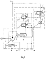
- Fig. 1 shows a hydraulic circuit diagram of an embodiment the power control device according to the invention, which is generally designated by reference number 1.
- a hydraulic pump 2 sucks the pressure medium from a pressure medium tank 4 and conveys the pressure medium in a work line 3, to which a consumer, not shown can be connected.
- the hydraulic pump 2 is a Drive shaft 5 preferably driven at a constant speed.
- Adjustment device that a first actuating piston 7a, a first actuating cylinder 8a, a second actuating piston 7b and has a second actuating cylinder 8b.
- the first actuating cylinder 8a there is an adjusting spring 9, which is the adjusting device 6 of the hydraulic pump 2 in the direction of maximum Funding volume applied.
- the actuating device 6 is the Hydraulic pump 2 in the direction of minimum displacement pivoted back.
- the secondary circuit 10 branches off from the work line 3 Secondary circuit 10.
- the secondary circuit 10 is generally with a current control device designated by reference numeral 11 a constant volume flow is fed to the working line 3.
- the outflow from the secondary circuit 10 into the pressure medium tank 4 takes place via a variable discharge throttle 12.
- the throttle cross section the flow restrictor 12 depends on the swivel angle the hydraulic pump 2.
- the current control device 11 is in the illustrated embodiment from a limit valve 13, which as 2/2-way valve is formed. Downstream of the relief valve 13 is a preferably adjustable Throttle 14.
- the throttle cross section of the throttle 14 is true preferably adjustable for adjustment purposes, but during the operation of the power control device according to the invention 1 unchangeable.
- the limit valve 13 is the pressure drop at the Throttle 14 controlled. If the pressure drop across the throttle 14 increases, therefore the flow through the decreases Limit valve 13. If, conversely, the pressure drop across the Throttle 14 decreases, the flow increases through the limit valve 13. Through this control mechanism hence the volume flow through the flow control device 14 regardless of the prevailing in the management 3 High pressure always adjusted to a constant value.
- the secondary pressure prevailing in the secondary circuit 10 acts on Control valve 17 a.
- the control valve 17 is in the embodiment designed as a 3/2-way valve and is by the Pressure difference between that prevailing in the working line 3 High pressure and that in the branch between the Current control device 11 and the outlet throttle 12 prevail Secondary pressure controlled.
- the control valve 17 has one first connection 18 connected to the working line 3, a second connection connected to the pressure medium tank 4 19 and one indirectly via a pressure relief valve 21 the second actuating cylinder 8b of the adjusting device 6 connected third connection 20. If the secondary pressure in the secondary circle 10 compared to that prevailing in the working line 3 High pressure rises, one becomes above that Pressure relief valve 21 leading connecting line 22 increasingly vented to the pressure medium tank 4.
- the pressure relief valve 21 is the one in the working line 3 prevailing high pressure. If the in the working line 3 prevailing high pressure by means of Return spring 21 exceeds the adjustable threshold, acts on the pressure relief valve 21 on the second actuating cylinder 8b of the actuating device 6 with that in the working line 3 prevailing high pressure, so that the actuator 6 the hydraulic pump 2 in the direction of the minimum delivery volume swings back.
- the operation of the power control device according to the invention 1 is as follows:
- the valve body of the Control valve 17 is due to the increased difference between the high pressure prevailing in the working line 3 and therefore the secondary pressure prevailing in the secondary circuit 10 moved that the connecting line 22 and thus the second actuating cylinder 8b with an increased actuating pressure be charged.
- the hydraulic pump 2 is therefore in the direction pivoted back to a reduced volume.
- FIG. 4 is an enlarged, fragmentary illustration of FIG Fig. 1.
- the throttle cross-section A from the outlet throttle 12 must be designed so that this throttle cross section A ⁇ from proportional to the root of the tangent of the pivot angle of the hydraulic pump. 2
- FIG. 2 and 3 show a constructive implementation according to an embodiment of the power control device 1.
- Fig. 2 shows a longitudinal section through the Power control device 1 and FIG. 3 a section along the line III-III in Fig. 2nd
- the elements of the power control device 1 are in the in Fig. 2 illustrated embodiment in a first Integrated housing block 40 and a second housing block 41, which are screwed together by screws 42 and 43.
- An input 44 becomes the one prevailing in the working line 3 High pressure supplied, while a first outlet 45 with the Pressure medium tank 4 is connectable.
- a second Output 46 via the connecting line shown in Fig. 1 16 connected to the control valve 17.
- the control valve 17 is not integrated in the two housing bodies 40 and 41, but arranged externally.
- one in one conventional flow control device provided Flow control valve the task of the invention Take over control valve 17.
- the limit valve 13 which is designed as a 2/2-way valve Current control device 11. Downstream of the Limit valve 13 is the throttle 14 of the limit valve 11 arranged.
- a first valve chamber 47 of the limiting valve 13 is over a connecting line 48 to the upstream portion the throttle 14 connected.
- the pressure drop therefore acts on the valve piston 51 on the throttle 14, the valve piston 51 in FIG. 2 is shifted further to the right and thus the opening cross-section of the limit valve 13 is reduced when the pressure drop across the throttle 14 increases.
- the valve piston 51 in Fig. 2 shifted to the left and that Limit valve 13 opened further when that Pressure drop at the throttle 14 is reduced.
- the throttle cross section the throttle 14 is cone-shaped by the distance End portion 52 of the grub screw 53 from the conical Recess 54 fixed in the first housing body 40. By turning the threaded pin 53 can therefore change the throttle cross section of the throttle 14 and by means of lock nut 55.
- the valve piston 51 of the limit valve 13 is by means of a return spring 56 in the opening direction of the limit valve 13 acted upon.
- the adjustable throttle 14 is located downstream Flow restrictor 12.
- the operation of the variable flow restrictor 12 can be in conjunction with Fig. 3, the one Section along the line III-III in Fig. 2 shows recognize.
- a swivel cradle 60 or swash plate of the hydraulic pump 2 is indicated in Fig. 3.
- the swivel cradle 60 is with a Pivot pin 61 is connected in a rotationally fixed manner, which when the Swivel cradle of the hydraulic pump 2 accordingly compared to fixed insert 67 is rotated.
- the fixed Insert part 67 is via a pin 69 with a housing part 40 connected.
- the pivot pin 61 has a junction area 62, an opening area 63 and an axial bore 64 on, the mouth area 62 with the mouth area 63 connects. Closes at the mouth area 63 there is a gap 65 connected to the first outlet 45.
- the pivot 61 When the pivot 61 is turned, a control edge 66 twisted so that it increasingly closes the gap 65 and thus the throttle cross section of the discharge throttle 12 is increasing narrowed.
- the length of the Gap 65 can be achieved that the throttle cross section Flow restrictor 12 proportional to the root of the tangent Swivel angle ⁇ of the hydraulic pump 4 or of the pivot 61 is.
- the gap 65 is to be designed, for example, that its length is not perpendicular to the plane of FIG. 2 constant but a function of the angle of rotation ⁇ .
- the invention is not based on the illustrated embodiment limited.
- other configurations can also be used the discharge throttle 12 or the current control device 11 Find use.
Landscapes
- Engineering & Computer Science (AREA)
- Mechanical Engineering (AREA)
- General Engineering & Computer Science (AREA)
- Fluid-Pressure Circuits (AREA)
- Control Of Positive-Displacement Pumps (AREA)
Abstract
Description
- Fig. 1
- einen hydraulischen Schaltplan eines Ausführungsbeispiels der erfindungsgemäßen Leistungsregelvorrichtung;
- Fig. 2
- eine geschnittene Darstellung eines konstruktiven Ausführungsbeispiels einer erfindungsgemäßen Leistungsregelvorrichtung;
- Fig. 3
- einen Schnitt entlang der Linie III-III in Fig. 2; und
- Fig. 4
- eine ausschnittsweise Darstellung von Fig. 1.
Claims (10)
- Leistungsregelvorrichtung (1) zur Regelung der hydraulischen Leistung einer in eine Arbeitsleitung (3) fördernden Hydropumpe (2), deren Schwenkwinkel (β) mittelseiner Verstellvorrichtung (6) verstellbar ist, miteiner mit der Arbeitsleitung (3) verbundenen Stromregeleinrichtung (11), die einem Nebenkreis (10) einen konstanten Volumenstrom (Qzu) zuführt,einer in dem Nebenkreis (10) angeordneten Ablaufdrossel (12), deren Drosselquerschnitt (Aab) von dem Schwenkwinkel (β) der Hydropumpe (2) abhängig ist, undeinem Steuerventil (17), das mit zunehmenden Nebendruck (px) in dem Nebenkreis (10) zwischen der Stromregeleinrichtung (11) und der Ablaufdrossel (12) die Verstellvorrichtung (6) in Richtung auf einen vergrößerten Schwenkwinkel (β) der Hydropumpe (2) beaufschlagt.
- Leistungsregelvorrichtung nach Anspruch 1,
dadurch gekennzeichnet,
daß die Stromregeleinrichtung (11) aus einer in dem Nebenkreis (10) angeordneten Drossel (14) und einem stromabwärts oder stromaufwärts der Drossel (14) in dem Nebenkreis (10) angeordneten Begrenzungsventil (13) besteht,
wobei das Begrenzungsventil (13) von dem Druckabfall (Δp) an der Drossel (14) angesteuert wird. - Leistungsregelvorrichtung nach Anspruch 2,
dadurch gekennzeichnet,
daß das Begrenzungsventil (13) ein 2/2-Wegeventil ist. - Leistungsregelvorrichtung nach einem der Ansprüche 1 bis 3,
dadurch gekennzeichnet,
daß sich der Drosselquerschnitt (Aab) der Ablaufdrossel (12) mit zunehmendem Schwenkwinkel (β) der Hydropumpe (2) ausgehend von der Neutralstellung vergrößert. - Leistungsregelvorrichtung nach Anspruch 4,
dadurch gekennzeichnet,
daß die Leistungsregelvorrichtung (1) die Leistung der Hydropumpe (2) auf eine konstante Maximalleistung begrenzt,
wobei der Öffnungsquerschnitt (Aab) der Ablaufdrossel (14) proportional zur Quadratwurzel des Tangens des Schwenkwinkels (β) der Hydropumpe (2) ist. - Leistungsregelvorrichtung nach einem der Ansprüche 1 bis 5,
dadurch gekennzeichnet,
daß das Steuerventil (17) ein 3/2-Wegeventil ist, mit einem mit der Arbeitsleitung (3) verbundenen ersten Anschluß (18), einem mit einem Druckmedium-Tank (4) verbundenen zweiten Anschluß (19) und einem zumindest mittelbar mit der Verstellvorrichtung (6) der Hydropumpe (2) verbundenen dritten Anschluß (20). - Leistungsregelvorrichtung nach einem der Ansprüche 1 bis 6,
dadurch gekennzeichnet,
daß zwischen dem Steuerventil (17) und der Verstellvorrichtung (6) der Hydropumpe (2) ein Druckbegrenzungsventil (21) angeordnet ist. - Leistungsregelvorrichtung nach einem der Ansprüche 1 bis 7,
dadurch gekennzeichnet,
daß ein Ventilkolben des Steuerventils (17) von der Druckdifferenz zwischen dem in der Arbeitsleitung (3) herrschenden Hochdruck (pHD) und dem in dem Nebenkreis (10) zwischen der Stromregeleinrichtung (11) und der Ablaufdrossel (12) herrschenden Nebendruck (px) beaufschlagt wird. - Leistungsregelvorrichtung nach einem der Ansprüche 1 bis 8,
dadurch gekennzeichnet, daß das Steuerventil (17) mit zunehmendem Nebendruck (px) in dem Nebenkreis (10) zwischen der Stromregeleinrichtung (11) und der Ablaufdrossel (12) einen Stellzylinder (8b) der Verstellvorrichtung (6) zunehmend zu einem Druckmedium-Tank (4) hin belüftet, um den Schwenkwinkel (β) der Hydropumpe (2) zu erhöhen. - Leistungsregelvorrichtung nach einem der Ansprüche 1 bis 9,
dadurch gekennzeichnet,
daß das die Ablaufdrossel (12) den Nebenkreis (10) mit einem Druckmedium-Tank (4) verbindet.
Applications Claiming Priority (2)
| Application Number | Priority Date | Filing Date | Title |
|---|---|---|---|
| DE19831587 | 1998-07-14 | ||
| DE1998131587 DE19831587C2 (de) | 1998-07-14 | 1998-07-14 | Leistungsregelvorrichtung zur Regelung der hydraulischen Leistung einer Hydropumpe |
Publications (3)
| Publication Number | Publication Date |
|---|---|
| EP0972939A2 true EP0972939A2 (de) | 2000-01-19 |
| EP0972939A3 EP0972939A3 (de) | 2000-08-23 |
| EP0972939B1 EP0972939B1 (de) | 2006-08-30 |
Family
ID=7874043
Family Applications (1)
| Application Number | Title | Priority Date | Filing Date |
|---|---|---|---|
| EP19990113343 Expired - Lifetime EP0972939B1 (de) | 1998-07-14 | 1999-07-09 | Leistungsregelvorrichtung für mehrere Hydropumpen |
Country Status (2)
| Country | Link |
|---|---|
| EP (1) | EP0972939B1 (de) |
| DE (2) | DE19831587C2 (de) |
Cited By (2)
| Publication number | Priority date | Publication date | Assignee | Title |
|---|---|---|---|---|
| EP1445488A3 (de) * | 2003-02-05 | 2004-09-01 | Liebherr Machines Bulle SA | Antrieb mit Hydromaschine |
| CN104235003A (zh) * | 2013-12-13 | 2014-12-24 | 江苏恒立液压有限公司 | 柱塞泵控制阀及其控制方法 |
Family Cites Families (5)
| Publication number | Priority date | Publication date | Assignee | Title |
|---|---|---|---|---|
| DE1188948B (de) * | 1960-07-16 | 1965-03-11 | Metallwerk Glockerau G M B H | Arbeitsfluessigkeitsmengen-Regeleinrichtung fuer hydrostatische Pumpen und Motoren |
| US4348159A (en) * | 1980-01-07 | 1982-09-07 | Rexnord Inc. | Convertible pump servo-valve control |
| DE3213958A1 (de) * | 1981-08-21 | 1983-03-03 | Robert Bosch Gmbh, 7000 Stuttgart | Elektrohydraulische verstelleinrichtung fuer eine hydrostatische maschine |
| DE3345264A1 (de) * | 1983-12-14 | 1985-06-27 | Brueninghaus Hydraulik Gmbh, 7240 Horb | Drehmomenten-regeleinrichtung fuer eine verstellbare hydropumpe |
| DE19626793C1 (de) * | 1996-07-03 | 1997-06-26 | Brueninghaus Hydromatik Gmbh | Hydraulische Regeleinrichtung zum parallelen Regeln mehrerer hydrostatischer Verstellpumpen |
-
1998
- 1998-07-14 DE DE1998131587 patent/DE19831587C2/de not_active Expired - Fee Related
-
1999
- 1999-07-09 DE DE59913812T patent/DE59913812D1/de not_active Expired - Fee Related
- 1999-07-09 EP EP19990113343 patent/EP0972939B1/de not_active Expired - Lifetime
Cited By (2)
| Publication number | Priority date | Publication date | Assignee | Title |
|---|---|---|---|---|
| EP1445488A3 (de) * | 2003-02-05 | 2004-09-01 | Liebherr Machines Bulle SA | Antrieb mit Hydromaschine |
| CN104235003A (zh) * | 2013-12-13 | 2014-12-24 | 江苏恒立液压有限公司 | 柱塞泵控制阀及其控制方法 |
Also Published As
| Publication number | Publication date |
|---|---|
| DE19831587C2 (de) | 2000-06-15 |
| EP0972939A3 (de) | 2000-08-23 |
| EP0972939B1 (de) | 2006-08-30 |
| DE19831587A1 (de) | 2000-02-24 |
| DE59913812D1 (de) | 2006-10-12 |
Similar Documents
| Publication | Publication Date | Title |
|---|---|---|
| EP0149787B2 (de) | Fördermengen-Regeleinrichtung für eine verstellbare Hydropumpe | |
| EP0826110B1 (de) | Verschiebbare hydraulische leistungs- bzw. momentenregeleinrichtung | |
| DE19909480A1 (de) | Druckausgleichsventil, Druckentlastungsregelventil und hydraulisch betriebene Vorrichtung | |
| EP0273214A2 (de) | Regeleinrichtung für eine verstellbare hydrostatische Maschine | |
| DE1953781A1 (de) | Hydraulisches System mit mindestens einer ueber mehrere Pumpen beaufschlagbaren hydraulischen Anlage | |
| DE3844401C2 (de) | Regeleinrichtung für eine Verstellpumpe | |
| DE10219850B3 (de) | Regeleinrichtung mit Grenzwertregelventil | |
| DE69206593T2 (de) | Steuerung mit Leistungsbegrenzung für eine Axialkolbenpumpe mit variablem Hub. | |
| DE68912475T2 (de) | Regelung für eine Pumpe mit veränderlicher Verdrängung. | |
| DE3919175C2 (de) | ||
| DE19831587C2 (de) | Leistungsregelvorrichtung zur Regelung der hydraulischen Leistung einer Hydropumpe | |
| DE3711053C2 (de) | ||
| DE2655966A1 (de) | Hydraulische regelvorrichtung mit einer stellpumpe | |
| DE3034115A1 (de) | Leistungsregler | |
| DE3528781C2 (de) | ||
| EP0284987B1 (de) | Regeleinrichtung für wenigstens zwei mit einer gemeinsamen Arbeitsdruckleitung in Verbindung stehende hydrostatische Maschinen | |
| DE19756600C1 (de) | Leistungsregelventil | |
| EP0284989B1 (de) | Regeleinrichtung für wenigstens zwei mit einer gemeinsamen Arbeitsdruckleitung in Verbindung stehende hydrostatische Maschinen | |
| DE3711049C2 (de) | ||
| DE3844404C2 (de) | Ventilanordnung zum lastunabhängigen Steuern mehrerer gleichzeitig betätigbarer hydraulischer Verbraucher | |
| EP0954703B1 (de) | Leistungs- bzw. momentenregeleinrichtung für mehrere hydropumpen | |
| DE3844398C2 (de) | Hydraulische Schaltung für eine Verstellpumpe | |
| DE19831586C2 (de) | Leistungsregelvorrichtung zur Regelung der hydraulischen Leistung in einer Arbeitsleitung |
Legal Events
| Date | Code | Title | Description |
|---|---|---|---|
| PUAI | Public reference made under article 153(3) epc to a published international application that has entered the european phase |
Free format text: ORIGINAL CODE: 0009012 |
|
| AK | Designated contracting states |
Kind code of ref document: A2 Designated state(s): DE FR GB IT SE |
|
| AX | Request for extension of the european patent |
Free format text: AL;LT;LV;MK;RO;SI |
|
| PUAL | Search report despatched |
Free format text: ORIGINAL CODE: 0009013 |
|
| AK | Designated contracting states |
Kind code of ref document: A3 Designated state(s): AT BE CH CY DE DK ES FI FR GB GR IE IT LI LU MC NL PT SE |
|
| AX | Request for extension of the european patent |
Free format text: AL;LT;LV;MK;RO;SI |
|
| RIC1 | Information provided on ipc code assigned before grant |
Free format text: 7F 04B 49/08 A, 7F 04B 49/00 B, 7F 04B 1/32 B |
|
| 17P | Request for examination filed |
Effective date: 20001027 |
|
| AKX | Designation fees paid |
Free format text: DE FR GB IT SE |
|
| 17Q | First examination report despatched |
Effective date: 20050428 |
|
| GRAP | Despatch of communication of intention to grant a patent |
Free format text: ORIGINAL CODE: EPIDOSNIGR1 |
|
| GRAS | Grant fee paid |
Free format text: ORIGINAL CODE: EPIDOSNIGR3 |
|
| GRAA | (expected) grant |
Free format text: ORIGINAL CODE: 0009210 |
|
| AK | Designated contracting states |
Kind code of ref document: B1 Designated state(s): DE FR GB IT SE |
|
| PG25 | Lapsed in a contracting state [announced via postgrant information from national office to epo] |
Ref country code: IT Free format text: LAPSE BECAUSE OF FAILURE TO SUBMIT A TRANSLATION OF THE DESCRIPTION OR TO PAY THE FEE WITHIN THE PRESCRIBED TIME-LIMIT;WARNING: LAPSES OF ITALIAN PATENTS WITH EFFECTIVE DATE BEFORE 2007 MAY HAVE OCCURRED AT ANY TIME BEFORE 2007. THE CORRECT EFFECTIVE DATE MAY BE DIFFERENT FROM THE ONE RECORDED. Effective date: 20060830 |
|
| REG | Reference to a national code |
Ref country code: GB Ref legal event code: FG4D Free format text: NOT ENGLISH |
|
| GBT | Gb: translation of ep patent filed (gb section 77(6)(a)/1977) |
Effective date: 20060830 |
|
| REF | Corresponds to: |
Ref document number: 59913812 Country of ref document: DE Date of ref document: 20061012 Kind code of ref document: P |
|
| REG | Reference to a national code |
Ref country code: SE Ref legal event code: TRGR |
|
| ET | Fr: translation filed | ||
| PLBE | No opposition filed within time limit |
Free format text: ORIGINAL CODE: 0009261 |
|
| STAA | Information on the status of an ep patent application or granted ep patent |
Free format text: STATUS: NO OPPOSITION FILED WITHIN TIME LIMIT |
|
| 26N | No opposition filed |
Effective date: 20070531 |
|
| PGFP | Annual fee paid to national office [announced via postgrant information from national office to epo] |
Ref country code: DE Payment date: 20080722 Year of fee payment: 10 |
|
| PGFP | Annual fee paid to national office [announced via postgrant information from national office to epo] |
Ref country code: FR Payment date: 20080715 Year of fee payment: 10 |
|
| PGFP | Annual fee paid to national office [announced via postgrant information from national office to epo] |
Ref country code: GB Payment date: 20080722 Year of fee payment: 10 |
|
| PGFP | Annual fee paid to national office [announced via postgrant information from national office to epo] |
Ref country code: SE Payment date: 20080714 Year of fee payment: 10 |
|
| EUG | Se: european patent has lapsed | ||
| GBPC | Gb: european patent ceased through non-payment of renewal fee |
Effective date: 20090709 |
|
| REG | Reference to a national code |
Ref country code: FR Ref legal event code: ST Effective date: 20100331 |
|
| PG25 | Lapsed in a contracting state [announced via postgrant information from national office to epo] |
Ref country code: FR Free format text: LAPSE BECAUSE OF NON-PAYMENT OF DUE FEES Effective date: 20090731 |
|
| PG25 | Lapsed in a contracting state [announced via postgrant information from national office to epo] |
Ref country code: GB Free format text: LAPSE BECAUSE OF NON-PAYMENT OF DUE FEES Effective date: 20090709 |
|
| PG25 | Lapsed in a contracting state [announced via postgrant information from national office to epo] |
Ref country code: DE Free format text: LAPSE BECAUSE OF NON-PAYMENT OF DUE FEES Effective date: 20100202 |
|
| PGFP | Annual fee paid to national office [announced via postgrant information from national office to epo] |
Ref country code: IT Payment date: 20100618 Year of fee payment: 11 |
|
| PG25 | Lapsed in a contracting state [announced via postgrant information from national office to epo] |
Ref country code: SE Free format text: LAPSE BECAUSE OF NON-PAYMENT OF DUE FEES Effective date: 20090710 Ref country code: IT Free format text: LAPSE BECAUSE OF NON-PAYMENT OF DUE FEES Effective date: 20100709 |