EP0972968A1 - Element de jonction de courroie transporteuse - Google Patents
Element de jonction de courroie transporteuse Download PDFInfo
- Publication number
- EP0972968A1 EP0972968A1 EP98113255A EP98113255A EP0972968A1 EP 0972968 A1 EP0972968 A1 EP 0972968A1 EP 98113255 A EP98113255 A EP 98113255A EP 98113255 A EP98113255 A EP 98113255A EP 0972968 A1 EP0972968 A1 EP 0972968A1
- Authority
- EP
- European Patent Office
- Prior art keywords
- conveyor belt
- belt
- connector according
- cover plate
- connecting elements
- Prior art date
- Legal status (The legal status is an assumption and is not a legal conclusion. Google has not performed a legal analysis and makes no representation as to the accuracy of the status listed.)
- Granted
Links
- 239000004744 fabric Substances 0.000 claims description 15
- 239000004753 textile Substances 0.000 claims description 7
- 238000004026 adhesive bonding Methods 0.000 claims description 3
- 230000008878 coupling Effects 0.000 description 6
- 238000010168 coupling process Methods 0.000 description 6
- 238000005859 coupling reaction Methods 0.000 description 6
- 210000002414 leg Anatomy 0.000 description 5
- 208000007101 Muscle Cramp Diseases 0.000 description 4
- 238000005452 bending Methods 0.000 description 1
- 230000015572 biosynthetic process Effects 0.000 description 1
- 230000006378 damage Effects 0.000 description 1
- 239000000463 material Substances 0.000 description 1
- 230000001012 protector Effects 0.000 description 1
- 230000035939 shock Effects 0.000 description 1
- 230000007704 transition Effects 0.000 description 1
- 210000000689 upper leg Anatomy 0.000 description 1
Images


Classifications
-
- F—MECHANICAL ENGINEERING; LIGHTING; HEATING; WEAPONS; BLASTING
- F16—ENGINEERING ELEMENTS AND UNITS; GENERAL MEASURES FOR PRODUCING AND MAINTAINING EFFECTIVE FUNCTIONING OF MACHINES OR INSTALLATIONS; THERMAL INSULATION IN GENERAL
- F16G—BELTS, CABLES, OR ROPES, PREDOMINANTLY USED FOR DRIVING PURPOSES; CHAINS; FITTINGS PREDOMINANTLY USED THEREFOR
- F16G3/00—Belt fastenings, e.g. for conveyor belts
- F16G3/02—Belt fastenings, e.g. for conveyor belts with series of eyes or the like, interposed and linked by a pin to form a hinge
- F16G3/04—Belt fastenings, e.g. for conveyor belts with series of eyes or the like, interposed and linked by a pin to form a hinge in which the ends of separate U-shaped or like eyes are attached to the belt by parts penetrating into it
-
- Y—GENERAL TAGGING OF NEW TECHNOLOGICAL DEVELOPMENTS; GENERAL TAGGING OF CROSS-SECTIONAL TECHNOLOGIES SPANNING OVER SEVERAL SECTIONS OF THE IPC; TECHNICAL SUBJECTS COVERED BY FORMER USPC CROSS-REFERENCE ART COLLECTIONS [XRACs] AND DIGESTS
- Y10—TECHNICAL SUBJECTS COVERED BY FORMER USPC
- Y10T—TECHNICAL SUBJECTS COVERED BY FORMER US CLASSIFICATION
- Y10T24/00—Buckles, buttons, clasps, etc.
- Y10T24/16—Belt fasteners
- Y10T24/1608—Hinged
- Y10T24/162—Pintle pin connected belt ends
Definitions
- the invention relates to a conveyor belt connector in series arranged connecting elements at the ends of the conveyor belt are fastened, the connecting elements by means of fastening elements, the the fasteners and the conveyor belt enforce, are connected to the tape ends, as well as with Traction means, which in the region of a conveyor belt end by means of a or several connecting elements connected to the conveyor belt are, the traction means in the conveying direction of the conveyor belt extend and at a distance from the respective, the traction means the traction element connecting the conveyor belt end by means of additional fastening elements with the conveyor belt connected is.
- DE 42 35 759 A1 basically discloses the band ends of conveyor belts and / or conveyor belt pieces with the help of to connect fasteners fastened to the ends of the tape.
- the fasteners themselves are used, for example With the help of screw, rivet or staple fasteners attached to the strap ends.
- U-shaped Connecting elements these are arranged in such a way that their eyelets at the ends of the band are in a combing position are located.
- a coupling rod can then be used to connect through the Eyelets are inserted.
- bar-shaped Fasteners bridge these at the joint Tape ends and are attached to both tape ends.
- GB-A-1 102 993 is a conveyor belt connector at the beginning known type, in which to increase the resilience the conveyor belt connection additionally arranged in the conveying direction, effective traction means across the entire width of the conveyor belt Find use that are designed as wires.
- the Wires are with the fasteners and one at a distance connected this arranged receiving plate, in particular pressed, the connecting elements and the receiving plates by means of the fastening elements and the additional fastening elements are connected to the conveyor belt.
- the conveyor belt is not thick in its end regions reduced.
- the connecting elements, the traction means and the Mounting plates are thus on the top and bottom of the Conveyor belt on this so that the conveyor belt connector in Operation of the conveyor belt on both sides a considerable wear is exposed.
- the goods conveyed by means of the conveyor belt not only comes in directly with the connecting elements System, but also with the traction means and the mounting plates. Because the thickness of the conveyor belt connector is greater than that of the Conveyor belt, it always happens when the conveyor belt connector Contacted drive or deflection drums of the conveyor belt hard impacts, which creates great forces in the conveyor belt connector be initiated. The increased wear on the conveyor belt connector is particularly in the two edge zones of the conveyor belt disadvantageous in which the connecting elements are higher Are subjected to stresses than those arranged further inside Fasteners.
- the task is solved with a conveyor belt connector type mentioned in that the traction means exclusively are arranged in the two side areas of the conveyor belt, wherein the respective traction device is designed as a belt, and the conveyor belt has at least one cover plate, which in Area of the belt is removed.
- the conveyor belt connector Due to the inventive design of the conveyor belt connector is a Breakage of the fasteners effectively prevented.
- the traction device as a belt ensures that this only is subject to low wear, which is not higher than that Belt wear.
- the thickness of the removed cover plate at least corresponds to the strength of the belt.
- the Outer surface of the belt at least one level with the outer surface the conveyor belt (in the area of the conveyor belt whose Top layer is not removed) forms.
- Opposite the outside surface the conveyor belt are only the fasteners the fasteners and the straps.
- the strength of each removed cover plate greater than the thickness of the belt, such that the additional fastener for connecting the belt essentially a plane on its side facing away from the belt with the outer surface of the adjacent cover plate of the conveyor belt forms.
- the belt preferably consists of a fabric, in particular of a textile fabric.
- the conveyor belt also expediently has one Fabric, in particular a textile fabric. This can be one or be multilayer and forms the tension member of the conveyor belt.
- the fabric with an upper and lower cover plate is preferred provided, which consists in particular of rubber.
- the respective Cover plate has the function of a wear layer. Optimal running properties and service life of the belts are then given if they have a similar elasticity as that around the cover plate or cover plates reduced conveyor belt.
- the straps are preferably on both the barrel and the support side arranged of the conveyor belt.
- the respective belt is designed in particular so that it as narrow, rectangular stripe is formed.
- the length of the Belt in the conveying direction of the conveyor belt is preferably two up to five times, especially three to four times as large as that Width.
- the dimensions of the recess in the conveyor belt Recording of the respective belt should be such that the Belt fills the recess.
- the additional connection of the belt to the conveyor belt can done in different ways. Preferably happens this by means of screws, rivets, staples with and without a base plate or fasteners.
- fasteners enclose the eyelets and legs these move the conveyor belt to the side and, if possible sure that the belt is across its entire width with the conveyor belt connected is.
- the respective belt can also be used with the Conveyor belt by means of gluing, vulcanizing or the like be connected to ensure that a flat connection between the belt and the reduced conveyor belt is guaranteed.
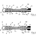
- FIGS. 1 to 4 there is a conveyor belt connector strip 1 for attaching the Ends 2 of a conveyor belt 3 from several connecting elements 4, using a soldered wire 5 to each other are aligned to form a unit. Any fastener 4 points to the formation of an eyelet 6 for one Coupling rod 7 an arcuate eyelet 8 and leg 9, 10 on.
- the conveyor belt 3 is constructed in three layers, such that a textile conveyor belt 21 with an upper cover plate 11 and a lower cover plate 16, for example made of rubber exist, is provided.
- the upper cover plate 11 in the edge regions 18 of the band end 2 removed, for example planed off, so that a rectangular Recess is formed.
- the conveyor belt 3 On the respective planed area the conveyor belt 3 is a traction device, which, like the 4 can be seen as a narrower, stripe-shaped Belt 12 is formed and its thickness about 1/3 the thickness of the upper cover plate 11.
- the belt 12 is made from a fabric, in particular a single or multi-layer Textile fabric.
- the belt 12 having a rectangular surface closes with the end face 14 of the respective band end 2.
- the legs 9 and 10 of the respective connecting element 4 reach around together with the eyelet 8 in assembled Condition of the respective band end 2 and the belt 12 U-shaped and are fastened to the respective band end 2 with the aid of fastening elements, which are designed as staples 15, attached holes aligned in pairs in the respective connecting element 4 as well as the conveyor belt 3 and the belt 12.
- fastening elements which are designed as staples 15, attached holes aligned in pairs in the respective connecting element 4 as well as the conveyor belt 3 and the belt 12.
- Both belts 12 are identical.
- the cover layers 11 and 16 have the same strength.
- the straps 12 extend away from the coupling rod 7 in the conveying direction 13 of the conveyor belt or opposite to the conveying direction and they are Belts 12 at a distance from the connecting elements 4 additionally connected to the conveyor belt in the area where the cover plate 11 or 16 is removed from the conveyor belt 3.
- the respective connecting element 17 is designed in the manner of the connecting element 4, but has no eyelet.
- the legs 9a and 10a of the Connecting element 17 have pairs aligned with each other Holes on.
- Fasteners in the form of staples 15a enforce the connecting elements 17 by the cover plates 11 and / or 16 freed tissue 21 of the conveyor belt 3 and the Belt or the straps 12. While the bent ends of the Cramps oriented in the direction of the coupling rod 7 are the bent ends of the cramps 15a from the coupling rod 7 way oriented.
- Each belt 12 is fastened by means of two connecting elements 4 and two connecting elements 17th
- the fabric 21 is a textile fabric, the one elasticity similar to that of the belt 12 the embodiment of Figure 2 is the thickness of the conveyor belt 3 (in the non-reduced area) approximately equal to the clamping strength of the Fasteners 15 and 15a.
- Figure 3 illustrates the conveyor belt in the region of a deflection drum 22.
- the Pull directions 13a and 13b extend perpendicular to the coupling rod 7.
- connection elements 17 are used which are identical the connecting elements 4 are designed, thus having eyelets 6.
- the connecting elements 17 are in this case on the side of the conveyor belt 3 and on the top and / or Underside of the conveyor belt 3 placed belt 12 pushed and fastened by means of the staples 15a.
- the respective connecting element 17 lies with its eyelet 6 on the conveyor belt 3 or is positioned at a short distance from it and it the legs 9 and 10 extend almost over the entire length Belt width 12.
- the strap 12 is fastened in the connecting elements 4 area facing away only by means of staples 15a, in this figure are essentially across the width of the Belt 12 arranged four cramps illustrated.
- Figure 7 shows instead of fastening with cramps, fastening the belt 12 by means of screws 19, Figure 8 an attachment by means of rivets 20.
- additional for fastening by means of the fastening elements of the belt 12 be connected to the fabric 21 by gluing or vulcanizing.
Landscapes
- Engineering & Computer Science (AREA)
- General Engineering & Computer Science (AREA)
- Mechanical Engineering (AREA)
- Belt Conveyors (AREA)
Priority Applications (3)
| Application Number | Priority Date | Filing Date | Title |
|---|---|---|---|
| DE59803275T DE59803275D1 (de) | 1998-07-16 | 1998-07-16 | Förderbandverbinder |
| EP98113255A EP0972968B1 (fr) | 1998-07-16 | 1998-07-16 | Element de jonction de courroie transporteuse |
| US09/352,228 US6196378B1 (en) | 1998-07-16 | 1999-07-13 | Conveyor belt connector and method |
Applications Claiming Priority (1)
| Application Number | Priority Date | Filing Date | Title |
|---|---|---|---|
| EP98113255A EP0972968B1 (fr) | 1998-07-16 | 1998-07-16 | Element de jonction de courroie transporteuse |
Publications (2)
| Publication Number | Publication Date |
|---|---|
| EP0972968A1 true EP0972968A1 (fr) | 2000-01-19 |
| EP0972968B1 EP0972968B1 (fr) | 2002-03-06 |
Family
ID=8232286
Family Applications (1)
| Application Number | Title | Priority Date | Filing Date |
|---|---|---|---|
| EP98113255A Expired - Lifetime EP0972968B1 (fr) | 1998-07-16 | 1998-07-16 | Element de jonction de courroie transporteuse |
Country Status (3)
| Country | Link |
|---|---|
| US (1) | US6196378B1 (fr) |
| EP (1) | EP0972968B1 (fr) |
| DE (1) | DE59803275D1 (fr) |
Cited By (1)
| Publication number | Priority date | Publication date | Assignee | Title |
|---|---|---|---|---|
| DE202024102710U1 (de) | 2024-05-24 | 2025-08-28 | Grimme Landmaschinenfabrik GmbH & Co. KG | Riemenanordnung für ein landwirtschaftliches Arbeitsgerät |
Families Citing this family (8)
| Publication number | Priority date | Publication date | Assignee | Title |
|---|---|---|---|---|
| ES2684415T3 (es) * | 2006-01-31 | 2018-10-02 | Thermodrive Llc | Conector de correa termoplástico con dedos |
| CN101400587B (zh) * | 2006-01-31 | 2012-11-07 | 热驱动有限责任公司 | 具有指状件的热塑性带连接器 |
| US7661256B2 (en) * | 2008-07-10 | 2010-02-16 | Deere & Company | Hybrid seam for a draper belt in an agricultural harvester |
| DE102009044080A1 (de) * | 2009-09-23 | 2011-04-21 | Contitech Transportbandsysteme Gmbh | Stahlseilfördergurt mit einem Verbindungsscharnier zum Koppeln zweier Gurtenden |
| RU2707434C2 (ru) | 2014-08-18 | 2019-11-26 | Флексибл Стил Лейсинг Компани | Соединитель конвейерных лент и способ его изготовления |
| USD808253S1 (en) | 2014-08-18 | 2018-01-23 | Flexible Steel Lacing Company | Fastener for a conveyor belt |
| DE102015214395A1 (de) * | 2015-07-29 | 2017-02-02 | Contitech Transportbandsysteme Gmbh | Gurt oder Gurtsegment |
| US12055195B2 (en) | 2022-01-28 | 2024-08-06 | Flexible Steel Lacing Company | Conveyor belt fastener |
Citations (5)
| Publication number | Priority date | Publication date | Assignee | Title |
|---|---|---|---|---|
| DE608511C (de) | 1935-01-24 | Curt Matthaei | Kantenschutz fuer aus Einschlaghaken gebildete Gelenkriemenverbinder | |
| DE648358C (de) * | 1937-07-29 | Paul Wever | Riemenverbindung | |
| GB1102993A (en) | 1966-02-04 | 1968-02-14 | Hayden Nilos Ltd | Improvements in or relating to fasteners for conveyor and like belts |
| GB1165254A (en) * | 1966-05-03 | 1969-09-24 | Goro Sa | Coupling for Conveyor Belts and the like |
| DE4235759A1 (de) | 1992-10-23 | 1994-05-05 | Mato Masch & Metallwaren | Verfahren zum Verbinden der Gurtenden von Förderbändern und Verbindungsmittel hierfür |
Family Cites Families (2)
| Publication number | Priority date | Publication date | Assignee | Title |
|---|---|---|---|---|
| FR1278024A (fr) * | 1960-10-24 | 1961-12-08 | Machine à fraiser les corps d'outils à plaquettes | |
| DE19724084A1 (de) * | 1997-06-07 | 1998-12-10 | Goro Sa | Riemenverbinder |
-
1998
- 1998-07-16 DE DE59803275T patent/DE59803275D1/de not_active Expired - Fee Related
- 1998-07-16 EP EP98113255A patent/EP0972968B1/fr not_active Expired - Lifetime
-
1999
- 1999-07-13 US US09/352,228 patent/US6196378B1/en not_active Expired - Fee Related
Patent Citations (5)
| Publication number | Priority date | Publication date | Assignee | Title |
|---|---|---|---|---|
| DE608511C (de) | 1935-01-24 | Curt Matthaei | Kantenschutz fuer aus Einschlaghaken gebildete Gelenkriemenverbinder | |
| DE648358C (de) * | 1937-07-29 | Paul Wever | Riemenverbindung | |
| GB1102993A (en) | 1966-02-04 | 1968-02-14 | Hayden Nilos Ltd | Improvements in or relating to fasteners for conveyor and like belts |
| GB1165254A (en) * | 1966-05-03 | 1969-09-24 | Goro Sa | Coupling for Conveyor Belts and the like |
| DE4235759A1 (de) | 1992-10-23 | 1994-05-05 | Mato Masch & Metallwaren | Verfahren zum Verbinden der Gurtenden von Förderbändern und Verbindungsmittel hierfür |
Cited By (1)
| Publication number | Priority date | Publication date | Assignee | Title |
|---|---|---|---|---|
| DE202024102710U1 (de) | 2024-05-24 | 2025-08-28 | Grimme Landmaschinenfabrik GmbH & Co. KG | Riemenanordnung für ein landwirtschaftliches Arbeitsgerät |
Also Published As
| Publication number | Publication date |
|---|---|
| EP0972968B1 (fr) | 2002-03-06 |
| DE59803275D1 (de) | 2002-04-11 |
| US6196378B1 (en) | 2001-03-06 |
Similar Documents
| Publication | Publication Date | Title |
|---|---|---|
| DE2437809B2 (de) | Siebboden sowie siebkoerper und rahmen hierfuer | |
| EP0442127B1 (fr) | Jonction de courroies transporteuses ou de transmission | |
| EP0747303B1 (fr) | Courroie à barreaux pour transporteurs à barraux | |
| EP0664074B1 (fr) | Crible convoyeur à barreaux | |
| EP0972968B1 (fr) | Element de jonction de courroie transporteuse | |
| DE2038532B2 (de) | Reißverschluß mit trennbarem Endglied | |
| DE69923306T2 (de) | Förderband mit variablen Abständen | |
| EP0596219B1 (fr) | Procédé de jonction d'éxtremités de convoies transporteurs et élément de jonction correspondant | |
| DE69307255T2 (de) | Kammförmige Einheit zur Aufnahme von durch ein Förderband angeführten Produkten | |
| DE2755100C2 (de) | Riemen für Siebkettenbänder von Kartoffelerntemaschinen | |
| EP0760438B1 (fr) | Bande transporteuse pour convoyeur à bande en auge | |
| EP1338825A1 (fr) | Jonction d'agrafes de courroie à crampons à une courroie et procédé | |
| EP0389831B1 (fr) | Dispositif pour ligaturer des éléments allongés | |
| EP0712797B1 (fr) | Courroie à barres pour bande transporteuse spécialement pour machines agricoles | |
| DE3903921A1 (de) | Endlosverbindung von zugfesten baendern insb. an siebstabbaendern | |
| CH628786A5 (de) | Zugelement fuer einen skischuhverschluss. | |
| EP0919117B1 (fr) | Transporteur incliné pour machines de récolte agricoles | |
| EP0176675A1 (fr) | Chenille | |
| DE10308823A1 (de) | Stab für umlaufende Stabbänder | |
| DE102016112301A1 (de) | Riemen als endloses Zugmittel für Förderbänder landwirtschaftlicher Maschinen, insbesondere Ballenpressen | |
| EP0085300A2 (fr) | Section de chenille pour véhicule chenillé | |
| DE69703894T2 (de) | Stabband-verstärkung und verfahren zur herstellung des entsprechenden stabbandes | |
| DE102016112305A1 (de) | Riemen als endloses Zugmittel für Förderbänder landwirtschaftlicher Maschinen, insbesondere Ballenpressen | |
| EP0432701B1 (fr) | Bande transporteuse à lattes | |
| DE9007192U1 (de) | Rollenkette |
Legal Events
| Date | Code | Title | Description |
|---|---|---|---|
| PUAI | Public reference made under article 153(3) epc to a published international application that has entered the european phase |
Free format text: ORIGINAL CODE: 0009012 |
|
| 17P | Request for examination filed |
Effective date: 19990519 |
|
| AK | Designated contracting states |
Kind code of ref document: A1 Designated state(s): DE GB |
|
| AX | Request for extension of the european patent |
Free format text: AL;LT;LV;MK;RO;SI |
|
| AKX | Designation fees paid |
Free format text: DE GB |
|
| GRAG | Despatch of communication of intention to grant |
Free format text: ORIGINAL CODE: EPIDOS AGRA |
|
| 17Q | First examination report despatched |
Effective date: 20010327 |
|
| GRAG | Despatch of communication of intention to grant |
Free format text: ORIGINAL CODE: EPIDOS AGRA |
|
| GRAH | Despatch of communication of intention to grant a patent |
Free format text: ORIGINAL CODE: EPIDOS IGRA |
|
| GRAG | Despatch of communication of intention to grant |
Free format text: ORIGINAL CODE: EPIDOS AGRA |
|
| GRAH | Despatch of communication of intention to grant a patent |
Free format text: ORIGINAL CODE: EPIDOS IGRA |
|
| GRAH | Despatch of communication of intention to grant a patent |
Free format text: ORIGINAL CODE: EPIDOS IGRA |
|
| REG | Reference to a national code |
Ref country code: GB Ref legal event code: IF02 |
|
| GRAA | (expected) grant |
Free format text: ORIGINAL CODE: 0009210 |
|
| AK | Designated contracting states |
Kind code of ref document: B1 Designated state(s): DE GB |
|
| PG25 | Lapsed in a contracting state [announced via postgrant information from national office to epo] |
Ref country code: GB Free format text: LAPSE BECAUSE OF FAILURE TO SUBMIT A TRANSLATION OF THE DESCRIPTION OR TO PAY THE FEE WITHIN THE PRESCRIBED TIME-LIMIT Effective date: 20020306 |
|
| REF | Corresponds to: |
Ref document number: 59803275 Country of ref document: DE Date of ref document: 20020411 |
|
| GBV | Gb: ep patent (uk) treated as always having been void in accordance with gb section 77(7)/1977 [no translation filed] |
Effective date: 20020306 |
|
| PLBE | No opposition filed within time limit |
Free format text: ORIGINAL CODE: 0009261 |
|
| STAA | Information on the status of an ep patent application or granted ep patent |
Free format text: STATUS: NO OPPOSITION FILED WITHIN TIME LIMIT |
|
| 26N | No opposition filed |
Effective date: 20021209 |
|
| PGFP | Annual fee paid to national office [announced via postgrant information from national office to epo] |
Ref country code: DE Payment date: 20030922 Year of fee payment: 6 |
|
| PG25 | Lapsed in a contracting state [announced via postgrant information from national office to epo] |
Ref country code: DE Free format text: LAPSE BECAUSE OF NON-PAYMENT OF DUE FEES Effective date: 20050201 |