EP0972987B1 - Injecteur de combustible muni d'un capteur remplaçable - Google Patents
Injecteur de combustible muni d'un capteur remplaçable Download PDFInfo
- Publication number
- EP0972987B1 EP0972987B1 EP99305505A EP99305505A EP0972987B1 EP 0972987 B1 EP0972987 B1 EP 0972987B1 EP 99305505 A EP99305505 A EP 99305505A EP 99305505 A EP99305505 A EP 99305505A EP 0972987 B1 EP0972987 B1 EP 0972987B1
- Authority
- EP
- European Patent Office
- Prior art keywords
- probe
- injector
- fuel injector
- conduit
- guide conduit
- Prior art date
- Legal status (The legal status is an assumption and is not a legal conclusion. Google has not performed a legal analysis and makes no representation as to the accuracy of the status listed.)
- Expired - Lifetime
Links
Images


Classifications
-
- F—MECHANICAL ENGINEERING; LIGHTING; HEATING; WEAPONS; BLASTING
- F23—COMBUSTION APPARATUS; COMBUSTION PROCESSES
- F23D—BURNERS
- F23D14/00—Burners for combustion of a gas, e.g. of a gas stored under pressure as a liquid
- F23D14/02—Premix gas burners, i.e. in which gaseous fuel is mixed with combustion air upstream of the combustion zone
-
- F—MECHANICAL ENGINEERING; LIGHTING; HEATING; WEAPONS; BLASTING
- F23—COMBUSTION APPARATUS; COMBUSTION PROCESSES
- F23C—METHODS OR APPARATUS FOR COMBUSTION USING FLUID FUEL OR SOLID FUEL SUSPENDED IN A CARRIER GAS OR AIR
- F23C7/00—Combustion apparatus characterised by arrangements for air supply
- F23C7/002—Combustion apparatus characterised by arrangements for air supply the air being submitted to a rotary or spinning motion
-
- F—MECHANICAL ENGINEERING; LIGHTING; HEATING; WEAPONS; BLASTING
- F23—COMBUSTION APPARATUS; COMBUSTION PROCESSES
- F23D—BURNERS
- F23D14/00—Burners for combustion of a gas, e.g. of a gas stored under pressure as a liquid
- F23D14/46—Details
- F23D14/72—Safety devices, e.g. operative in case of failure of gas supply
- F23D14/82—Preventing flashback or blowback
-
- F—MECHANICAL ENGINEERING; LIGHTING; HEATING; WEAPONS; BLASTING
- F23—COMBUSTION APPARATUS; COMBUSTION PROCESSES
- F23N—REGULATING OR CONTROLLING COMBUSTION
- F23N5/00—Systems for controlling combustion
- F23N5/02—Systems for controlling combustion using devices responsive to thermal changes or to thermal expansion of a medium
- F23N5/10—Systems for controlling combustion using devices responsive to thermal changes or to thermal expansion of a medium using thermocouples
-
- F—MECHANICAL ENGINEERING; LIGHTING; HEATING; WEAPONS; BLASTING
- F23—COMBUSTION APPARATUS; COMBUSTION PROCESSES
- F23C—METHODS OR APPARATUS FOR COMBUSTION USING FLUID FUEL OR SOLID FUEL SUSPENDED IN A CARRIER GAS OR AIR
- F23C2900/00—Special features of, or arrangements for combustion apparatus using fluid fuels or solid fuels suspended in air; Combustion processes therefor
- F23C2900/07002—Premix burners with air inlet slots obtained between offset curved wall surfaces, e.g. double cone burners
-
- F—MECHANICAL ENGINEERING; LIGHTING; HEATING; WEAPONS; BLASTING
- F23—COMBUSTION APPARATUS; COMBUSTION PROCESSES
- F23N—REGULATING OR CONTROLLING COMBUSTION
- F23N2900/00—Special features of, or arrangements for controlling combustion
- F23N2900/05005—Mounting arrangements for sensing, detecting or measuring devices
Definitions
- This invention relates to fuel injectors for turbine engines, and particularly to a premixing fuel injector that includes an easily replaceable sensor for monitoring conditions in the interior of the injector.
- NOx nitrous oxides
- One of the principal NOx suppression strategies is to burn a stoichiometrically lean, thoroughly blended fuel-air mixture.
- fuel and air are aggressively blended together in an internal mixing chamber of a premixing fuel injector before being introduced into the engine combustion chamber and burned.
- the lean, thoroughly blended fuel-air mixture results in a uniformly low combustion flame temperature -- a prerequisite for NOx suppression.
- premixing fuel injectors that premix fuel and air are effective at producing the requisite, intimately blended fuel-air mixture, they suffer from certain shortcomings.
- the presence of the fuel-air mixture inside the injector can encourage the combustion flame to migrate into the mixing chamber where the flame can cause considerable damage.
- premixing fuel injectors have a number of physical features designed to resist flame ingestion and to quickly disgorge any flame that overcomes the ingestion resistance. Despite these features, a flame can occasionally become anchored inside the mixing chamber. Therefore a premixing injector may also have one or more temperature sensors to detect the presence of flame so that appropriate corrective action can be taken.
- the temperature sensor is a thermocouple welded to the interior of the injector with its sensing junction positioned near the mixing chamber.
- thermocouple Although the welded thermocouple is effective for monitoring internal temperature, it is not easily replaceable. If the thermocouple malfunctions, maintenance technicians must first remove the affected fuel injector from the engine. The fuel injector is then disassembled, the weld joints are broken to release the inoperative thermocouple, and a replacement thermocouple is welded into position. Finally, the injector is reassembled and reinstalled in the engine. Clearly, this procedure is unacceptably time consuming and labor intensive. Moreover, industrial operations are disrupted and operating revenue is sacrificed while the engine is out of service. An engine operator may keep one or more spare injectors on hand to minimize the length of service disruptions. However, this option is unappealing because of the expense of acquiring and stockpiling spare injectors.
- EP-A-0 816 760 discloses an injector having a detector arranged in a conduit arranged in the injector.
- the guide conduit has a nonlinear shape
- the probe is deformable so that it conforms readily to the nonlinear shape, thereby facilitating insertion of the probe into the conduit.
- the probe is also sufficiently rigid to overcome any insertion resistance offered by the conduit.
- the injector is suitable for engines in which straight line access between the externally accessible conduit opening and the prescribed location of the sensor is impractical or unrealizable.
- the end of the conduit remote from the opening is closed, and the sensor element resides at the tip of the probe.
- the probe is longitudinally oversized relative to the conduit so that when the probe is correctly installed, the sensor contacts the closed end of the conduit to maximize the sensor's transient responsiveness.
- the probe can be installed or removed without appreciable twisting or rotation of the probe relative to the conduit, thereby minimizing the potential for damaging the probe during installation or removal.
- Figure 1 is a schematic, cross sectional side elevation showing a premixing fuel injector installed in the combustor module of an industrial gas turbine engine.
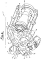
- Figure 2 is a more detailed, perspective view of the premixing fuel injector of Figure 1 partially cut away to expose the interior of the injector.
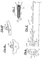
- FIG. 3 is a more detailed, cross sectional side elevation of the fuel injector of Figure 1.
- Figure 4A and 4B are views in the direction 4--4 of Figure 3 showing a portion of a guide conduit for a sensor probe and a clamp for securing the conduit to the interior of the injector.
- Figure 5 is a side view of a sensor probe having a thermocouple junction at its tip end.
- Figure 6 is an end view of the sensor probe taken in the direction 6--6 of Figure 5.
- Figure 7 is an enlarged view of the tip end of the sensor probe of Fig. 5 showing the thermocouple leads and a thermocouple junction.
- FIGS 1-3 illustrate a premixing fuel injector 10 for an industrial gas turbine engine.
- the injector which is one of a plurality of injectors used in the engine, includes a frame 12 having a support 16 that extends from a mounting flange 18 to a forward bulkhead 20.
- a pair of arcuate scrolls 22a, 22b project longitudinally from the forward bulkhead to an aft bulkhead 26 and have a fuel-air discharge port 28 extending therethrough.
- Each scroll extends approximately 180° about fuel injector centerline 30, and is radially offset from the centerline so that the circumferential extremities of the scrolls cooperate to define a pair of longitudinally extending primary air intake slots 32a, 32b.
- the scrolls also define the radially outer boundary of an internal chamber 34.
- Each scroll includes an enlarged portion that accommodates a primary fuel supply manifold 36a, 36b and an array of primary fuel injection orifices 40 distributed along the length of the manifold.
- the injector 10 also includes a centerbody 46 embraced by and radially spaced from the scrolls.
- the centerbody includes a base 48 secured to the forward bulkhead 20, a shell 50 extending longitudinally from the base, a fuel-air injection insert 52 nested within the aft end of the shell and a secondary fuel supply tube 54 connecting the insert to a fuel passage in the centerbody base 48.
- the centerbody shell segregates internal chamber 34 into an annular main chamber 34a, radially bounded by the shell and the scrolls, and a subchamber 34b.
- the main chamber is a mixing chamber for intermixing primary air and primary fuel.
- the subchamber is a secondary air supply plenum for feeding secondary air to the insert 52.
- Dual primary fuel lines 56a, 56b and secondary fuel line 58 are connected to a fuel supply, not shown, and penetrate through the support flange 18 to supply fuel to the fuel manifolds 36a, 36b and the secondary fuel tube 54.
- the above described injector is effective at thoroughly premixing the primary fuel and air, and therefore promotes clean combustion and inhibits NOx formation.
- the presence of the thoroughly blended fuel-air mixture inside the mixing chamber 34a can encourage the flame 64 to migrate into the chamber where, if not quickly disgorged or extinguished, it can cause considerable damage.
- One method for extinguishing the flame includes monitoring the temperature inside the mixing chamber and, if the temperature suggests that a flame is present, temporarily interrupting the fuel supply to the injector.
- the illustrated injector includes means for monitoring temperature at a prescribed location 68 near the aft end of the mixing chamber, and specifically within the fuel-air discharge port 28.
- the temperature monitoring means includes a substantially longitudinally continuous guide conduit indicated generally at 70.
- the conduit includes a proximate tube 72 with an access opening 74 having a metallic seal ring 75 installed therein.
- the access opening is circumscribed by a mounting pad 76 that includes a pair of bolt receptacles 77.
- the access opening is accessible externally of the injector and, when the injector is mounted on case 42, externally of the case 42 as well.
- the proximate tube extends from the access opening to a pair of tapered passages 78a, 78b (Fig.
- An intermediate tube 80 (Fig's. 1 and 3 ) having a diameter smaller than that of the proximate tube originates at the passage 78b and extends along the interior of the centerbody shell.
- a set of saddle clamps 86 are brazed to the intermediate tube and to the inside surface of the centerbody shell to secure the tube to the shell.
- a distal tube 82 having a diameter smaller than that of the intermediate tube projects from the intermediate tube to the prescribed location 68 and is brazed to the inside surface of the centerbody shell.
- the distal end 84 of the conduit 70 which is the remote end of the distal tube 82, is closed.
- the temperature monitoring means also includes an insertable probe, exemplified by sensor probe 88, removably installed in the guide conduit.
- the sensor probe has a base 90 and a single piece swaged shank 92 that extends from the base to a tip end 93.
- Bolt holes 94 extend through the base so that the sensor probe may be removably secured to mounting pad 76. If desired, the bolt holes may be spaced unequally from the probe centerline 96, and the corresponding bolt receptacles 77 may be correspondingly spaced from the center of the access opening 74 to ensure that the probe is secured in a preferred, predesignated orientation.
- the probe shank 92 encapsulates a pair of thermocouple leads 98a, 98b separated from the shank and from each other by electrically nonconductive refractory insulation 100.
- the leads are individually connected to electrical terminals 104 projecting from the probe base. At the tip end 93 of the shank the leads join together to form a thermocouple sensing junction 106.
- the shank itself is at least elastically deformable so that it readily conforms to the nonlinear shape of the guide conduit when inserted longitudinally therein through access opening 74.
- the shank of the illustrated probe is both elastically deformable and plastically deformable. That is, once the probe has been inserted into and subsequently removed from the guide conduit, the shank springs back toward its original shape, but also exhibits a permanent set due to the nonlinear shape of the guide conduit. However the shank is also rigid enough to overcome any insertion resistance that the conduit might offer.
- probe insertability and conformability are enhanced by a shank having longitudinally varying flexibility. As seen in Fig.
- the shank has a proximate segment 108, an intermediate segment 110 and a distal segment 112 with short transition segments 114, 116 linking the intermediate segment to the proximate and distal segments.
- the proximate, intermediate and distal segments are each characterized by a different cross sectional area and hence by a different degree of flexibility so that the flexibility of the shank varies in an approximately stepwise manner.
- rigidity is desirable for enhancing insertability.
- the cross sectional area of shank segment 108 is relatively large and the shank is relatively rigid.
- flexibility is desirable for ensuring that the shank can follow the contour of the guide conduit.
- the cross sectional area of shank segment 112 is relatively small and the shank is relatively flexible. If desired, the shank could be made with a continuously varying cross sectional area to give the probe a continuously varying flexibility.
- the probe base 90 seats against the mounting pad 76 and is bolted thereto by bolts, not illustrated.
- the probe shank is longitudinally oversized relative to the length of the guide conduit so that the thermocouple junction 106 at the tip 93 of the probe is urged into contact with the closed, distal end 84 of the conduit (Fig. 7 ).
- the probe shank 92 buckles slightly so that the shank presses against the internal sidewall of the conduit at one or more contact points 118. The contact between the thermocouple junction 106 and the distal end 84 of the conduit enhances the junction's responsiveness to temperature changes inside the injector mixing chamber 34a.
- the conduit length L c is about 17.75 inches (45.1 cm.) and the shank length L s is about 0.1 inches (0.25 cm.) longer than the conduit length.
- a second temperature sensing system substantially similar to the one just described and indicated with primed reference characters, is included to assure reliable flame detection.
- replacement of the sensor probe can be accomplished without removing the injector from the engine, and without disassembling the injector. Instead, removal of the sensor probe is accomplished by merely unbolting the probe base 90 from the mounting pad 76 and sliding the probe longitudinally out of the guide conduit. Probe installation is accomplished by sliding the probe shank longitudinally into the conduit and reconnecting the probe base to the mounting pad. Neither installation nor removal of the probe requires any appreciable rotation or twisting of the probe relative to the guide conduit. Accordingly, the risk of damage to the probe or to the sensor element 106 is minimized.
- the illustrated probe could carry multiple sensor elements rather than a single sensor element positioned at the probe tip 93.
- the sensor element or elements need not be thermocouple sensing junctions, but may instead be any sensor element capable of responding to conditions of interest inside the injector.
Landscapes
- Engineering & Computer Science (AREA)
- Chemical & Material Sciences (AREA)
- Combustion & Propulsion (AREA)
- Mechanical Engineering (AREA)
- General Engineering & Computer Science (AREA)
- Measuring Temperature Or Quantity Of Heat (AREA)
- Fuel-Injection Apparatus (AREA)
Claims (13)
- Injecteur de carburant à prémélange comprenant :un cadre d'injecteur (12) dont une partie au moins contient une chambre intérieure (34) ;un conduit de guidage (70) ayant une extrémité proximale (72) avec une ouverture d'accès (74) accessible depuis l'extérieur de l'injecteur pour recevoir une sonde encastrable (88), et une extrémité distale (84) positionnée à l'intérieur de l'injecteur ; etune sonde de détecteur (88) installée dans le conduit de guidage (70) et ayant une extrémité inférieure (90), une extrémité supérieure (93) et au moins un élément de détecteur (106) pour détecter les conditions de détection dans l'injecteur ; caractérisé en ce que ladite sonde de détecteur (88) est installée de manière amovible dans le conduit de guidage (70) et en ce que la chambre intérieure comprend une chambre principale (34a) et une chambre secondaire (34b), le conduit de guidage (70) se prolongeant dans la chambre secondaire (34b).
- Injecteur de carburant selon la revendication 1, dans lequel ledit cadre d'injecteur (12) comprend un support d'injecteur (16) et un couple de spirales arquées décentrées de façon radiale (22a, 22b) se prolongeant à partir du support (16) ; et comprenant de plusledit conduit de guidage (70) se prolongeant dans le plenum (34b), etun corps central (46) circonscrit par les spirales (22a, 22b) et espacé de façon radiale par rapport à celles-ci, l'association du corps central et des spirales définissant ladite chambre principale (34a), ladite chambre principale (34a) étant une chambre annulaire de mélange, le corps central (46) définissant également l'extrémité extérieure de façon radiale de ladite chambre secondaire (34b), ladite chambre secondaire (34b) étant un plenum d'admission d'air secondaire ;
ledit élément de détecteur ayant pour fonction de détecter les conditions dans la chambre de mélange (34a). - Injecteur de carburant selon la revendication 1 ou 2, dans lequel le conduit de guidage (70) a une forme non linéaire et dans lequel la sonde de détecteur (88) est déformable afin de se conformer à la forme non linéaire.
- Injecteur de carburant selon la revendication 1, 2 ou 3, dans lequel la sonde de détecteur (88) est suffisamment rigide pour vaincre la résistance qui lui est opposée lors d'une insertion longitudinale de la sonde dans le conduit de guidage (70).
- Injecteur de carburant selon la revendication 3, dans lequel la sonde de détecteur (88) a une flexibilité variant de manière longitudinale qui augmente de l'extrémité inférieure (90) à l'extrémité supérieure (93), rendant ainsi la sonde suffisamment déformable pour qu'elle se conforme à la forme non linéaire du conduit de guidage (70) et suffisamment rigide pour qu'elle vainque la résistance qui lui est opposée lors d'une insertion longitudinale dans le conduit de guidage.
- Injecteur de carburant selon la revendication 5, dans lequel la flexibilité variant de manière longitudinale de la sonde de détecteur (88) varie approximativement par paliers.
- Injecteur de carburant selon la revendication 6, dans lequel la flexibilité par paliers est attribuable à une variation approximativement par paliers de la section transversale de la sonde de détecteur.
- Injecteur de carburant selon l'une quelconque des revendications précédentes, dans lequel l'extrémité distale (84) du conduit (70) est fermée, l'élément de détecteur (106) se trouve à l'extrémité supérieure de la sonde de détecteur (88) et la sonde (88) est longitudinalement surdimensionnée par rapport au conduit de guidage (70) de façon à ce que, lorsque la sonde (88) est correctement installée dans le conduit de guidage, l'élément de détecteur (106) est poussé en contact avec l'extrémité distale fermée (84) du conduit de guidage (70).
- Injecteur de carburant selon la revendication 8, dans lequel la sonde de détecteur (88) est longitudinalement surdimensionnée de manière suffisante pour que, lorsque la sonde est correctement installée dans le conduit de guidage (70), la sonde (88) est poussée en contact avec la paroi latérale du conduit (70).
- Injecteur de carburant selon l'une quelconque des revendications précédentes, dans lequel la sonde de détecteur (88) peut être installée et retirée du conduit de guidage (70) en translatant la sonde (88) de manière longitudinale par rapport au conduit sans rotation ou torsion notable de la sonde (88) par rapport au conduit (70).
- Injecteur de carburant selon l'une quelconque des revendications précédentes, dans lequel l'élément de détecteur (106) est un élément de détection de température et la condition détectée est la température.
- Injecteur de carburant selon la revendication 11, dans lequel l'élément de détection de température est une jonction de détection à thermocouple (106).
- Injecteur de carburant selon l'une quelconque des revendications précédentes comprenant un moyen pour assembler l'injecteur dans un carter de moteur afin que l'ouverture d'accès soit accessible depuis l'extérieur du carter de moteur.
Applications Claiming Priority (4)
| Application Number | Priority Date | Filing Date | Title |
|---|---|---|---|
| US11674098A | 1998-07-16 | 1998-07-16 | |
| US116740 | 1998-07-16 | ||
| US162833 | 1998-09-29 | ||
| US09/162,833 US6094904A (en) | 1998-07-16 | 1998-09-29 | Fuel injector with a replaceable sensor |
Publications (3)
| Publication Number | Publication Date |
|---|---|
| EP0972987A2 EP0972987A2 (fr) | 2000-01-19 |
| EP0972987A3 EP0972987A3 (fr) | 2000-03-08 |
| EP0972987B1 true EP0972987B1 (fr) | 2003-09-24 |
Family
ID=26814566
Family Applications (1)
| Application Number | Title | Priority Date | Filing Date |
|---|---|---|---|
| EP99305505A Expired - Lifetime EP0972987B1 (fr) | 1998-07-16 | 1999-07-12 | Injecteur de combustible muni d'un capteur remplaçable |
Country Status (7)
| Country | Link |
|---|---|
| US (1) | US6094904A (fr) |
| EP (1) | EP0972987B1 (fr) |
| JP (1) | JP2000045792A (fr) |
| CN (1) | CN1209553C (fr) |
| CA (1) | CA2276862A1 (fr) |
| DE (1) | DE69911514T2 (fr) |
| RU (1) | RU2227871C2 (fr) |
Families Citing this family (19)
| Publication number | Priority date | Publication date | Assignee | Title |
|---|---|---|---|---|
| US6321541B1 (en) * | 1999-04-01 | 2001-11-27 | Parker-Hannifin Corporation | Multi-circuit multi-injection point atomizer |
| US6711898B2 (en) | 1999-04-01 | 2004-03-30 | Parker-Hannifin Corporation | Fuel manifold block and ring with macrolaminate layers |
| ITMI20012780A1 (it) * | 2001-12-21 | 2003-06-21 | Nuovo Pignone Spa | Dispositivo di iniezione principale di combustibile liquido per camera di combustione singola dotata di camera di pre-miscelamento di una tu |
| ITMI20032621A1 (it) * | 2003-12-30 | 2005-06-30 | Nuovo Pignone Spa | Sistema di combustione a basse emissioni inquinanti |
| CN100590355C (zh) | 2004-02-12 | 2010-02-17 | 阿尔斯通技术有限公司 | 具有限定圆锥形涡旋室的涡旋发生器的、传感器监视的预混合燃烧器 |
| JP4606867B2 (ja) * | 2004-12-22 | 2011-01-05 | 株式会社荏原製作所 | シース型計測器及び軸受、並びに回転機械 |
| GB0502438D0 (en) * | 2005-02-05 | 2005-03-16 | Alstom Technology Ltd | Fuel injection system and method of monitoring purging of the same |
| ATE479054T1 (de) | 2005-03-09 | 2010-09-15 | Alstom Technology Ltd | Vormischbrenner zum erzeugen eines zündfähigen brennstoff-luftgemisches |
| US9568197B2 (en) * | 2007-07-09 | 2017-02-14 | United Technologies Corporation | Integrated fuel nozzle with feedback control for a gas turbine engine |
| US8087824B2 (en) * | 2007-07-26 | 2012-01-03 | Honeywell International Inc. | Aircraft brake assembly having a temperature probe and method of mounting a temperature probe in a brake assembly |
| US8141368B2 (en) | 2008-11-11 | 2012-03-27 | Delavan Inc | Thermal management for fuel injectors |
| US20130040254A1 (en) * | 2011-08-08 | 2013-02-14 | General Electric Company | System and method for monitoring a combustor |
| JP6018714B2 (ja) * | 2012-11-21 | 2016-11-02 | ゼネラル・エレクトリック・カンパニイ | コーキング防止液体燃料カートリッジ |
| FR3023584B1 (fr) * | 2014-07-08 | 2016-08-12 | Snecma | Turbomachine a double flux equipee de moyens de mesure d'un parametre |
| CN104534474B (zh) * | 2014-12-08 | 2018-02-09 | 北京华清燃气轮机与煤气化联合循环工程技术有限公司 | 一种燃气轮机及应用该燃气轮机检测回火的方法 |
| US11022041B2 (en) | 2015-10-13 | 2021-06-01 | Raytheon Technologies Corporation | Sensor snubber block for a gas turbine engine |
| JP6945468B2 (ja) * | 2018-02-06 | 2021-10-06 | 三菱パワー株式会社 | ガスタービン燃焼器、ガスタービン及びガスタービン燃焼器の制御方法 |
| CN113237109B (zh) * | 2021-05-31 | 2022-10-04 | 宁波方太厨具有限公司 | 一种烟灶联动控制装置、灶具及吸油烟机 |
| CN115614741B (zh) * | 2022-10-24 | 2025-07-25 | 意高环保装备(广州)有限公司 | 一种具有燃料油监测装置的燃烧器 |
Citations (1)
| Publication number | Priority date | Publication date | Assignee | Title |
|---|---|---|---|---|
| US2806075A (en) * | 1954-07-27 | 1957-09-10 | Gen Motors Corp | Thermocouple |
Family Cites Families (19)
| Publication number | Priority date | Publication date | Assignee | Title |
|---|---|---|---|---|
| US3078672A (en) * | 1959-03-28 | 1963-02-26 | Maschf Augsburg Nuernberg Ag | Process and apparatus for operating a continuous or intermittent combustion engine |
| US3592061A (en) * | 1969-08-22 | 1971-07-13 | Gen Motors Corp | Gas turbine airfoil having integral thermocouple |
| GB1503042A (en) * | 1974-05-21 | 1978-03-08 | Smiths Industries Ltd | Radiation-detecting devices |
| US4132114A (en) * | 1977-03-14 | 1979-01-02 | Westinghouse Electric Corp. | Temperature probe assembly for gas turbine engine |
| US4668162A (en) * | 1985-09-16 | 1987-05-26 | Solar Turbines Incorporated | Changeable cooling control system for a turbine shroud and rotor |
| US4948264A (en) * | 1986-07-07 | 1990-08-14 | Hook Jr Richard B | Apparatus for indirectly determining the temperature of a fluid |
| US4778538A (en) * | 1987-07-15 | 1988-10-18 | Westinghouse Electric Corp. | Dual temperature sensing device having twin well thermowell for dual resistance temperature detectors |
| US4934137A (en) * | 1988-12-14 | 1990-06-19 | Allied-Signal Inc. | Temperature measurement in turbine engines |
| US5301061A (en) * | 1989-07-27 | 1994-04-05 | Olympus Optical Co., Ltd. | Endoscope system |
| CH680467A5 (fr) * | 1989-12-22 | 1992-08-31 | Asea Brown Boveri | |
| US5185996A (en) * | 1990-12-21 | 1993-02-16 | Allied-Signal Inc. | Gas turbine engine sensor probe |
| US5307634A (en) * | 1992-02-26 | 1994-05-03 | United Technologies Corporation | Premix gas nozzle |
| GB2272058B (en) * | 1992-10-30 | 1997-01-29 | Schlumberger Ind Ltd | Thermocouple probe |
| US5466067A (en) * | 1993-09-17 | 1995-11-14 | The B. F. Goodrich Company | Multifunctional air data sensing probes |
| EP0765453B1 (fr) * | 1994-06-24 | 2001-01-10 | United Technologies Corporation | Injecteur pilote pour moteurs a turbine a gaz |
| US5671597A (en) * | 1994-12-22 | 1997-09-30 | United Technologies Corporation | Low nox fuel nozzle assembly |
| US5706643A (en) * | 1995-11-14 | 1998-01-13 | United Technologies Corporation | Active gas turbine combustion control to minimize nitrous oxide emissions |
| JPH1082526A (ja) * | 1996-06-24 | 1998-03-31 | General Electric Co <Ge> | 予混合燃焼器システムにおけるフラッシュバックの発生を検出する装置 |
| US5865609A (en) * | 1996-12-20 | 1999-02-02 | United Technologies Corporation | Method of combustion with low acoustics |
-
1998
- 1998-09-29 US US09/162,833 patent/US6094904A/en not_active Expired - Lifetime
-
1999
- 1999-06-29 CA CA002276862A patent/CA2276862A1/fr not_active Abandoned
- 1999-07-12 EP EP99305505A patent/EP0972987B1/fr not_active Expired - Lifetime
- 1999-07-12 DE DE69911514T patent/DE69911514T2/de not_active Expired - Lifetime
- 1999-07-13 CN CN99110343.2A patent/CN1209553C/zh not_active Expired - Fee Related
- 1999-07-13 RU RU99115473/06A patent/RU2227871C2/ru not_active IP Right Cessation
- 1999-07-16 JP JP11202722A patent/JP2000045792A/ja active Pending
Patent Citations (1)
| Publication number | Priority date | Publication date | Assignee | Title |
|---|---|---|---|---|
| US2806075A (en) * | 1954-07-27 | 1957-09-10 | Gen Motors Corp | Thermocouple |
Also Published As
| Publication number | Publication date |
|---|---|
| DE69911514T2 (de) | 2004-04-22 |
| CN1245250A (zh) | 2000-02-23 |
| JP2000045792A (ja) | 2000-02-15 |
| DE69911514D1 (de) | 2003-10-30 |
| CA2276862A1 (fr) | 2000-01-16 |
| EP0972987A3 (fr) | 2000-03-08 |
| EP0972987A2 (fr) | 2000-01-19 |
| US6094904A (en) | 2000-08-01 |
| CN1209553C (zh) | 2005-07-06 |
| RU2227871C2 (ru) | 2004-04-27 |
Similar Documents
| Publication | Publication Date | Title |
|---|---|---|
| EP0972987B1 (fr) | Injecteur de combustible muni d'un capteur remplaçable | |
| EP0547808B1 (fr) | Chambre de combustion avec alimentation en air étagée | |
| JP4641648B2 (ja) | モジュール式燃焼器ドーム | |
| EP2813683B1 (fr) | Systèmes d'allumage continu | |
| US6581386B2 (en) | Threaded combustor baffle | |
| US6098407A (en) | Premixing fuel injector with improved secondary fuel-air injection | |
| JP4815513B2 (ja) | ガスタービン燃焼器 | |
| US8438853B2 (en) | Combustor end cap assembly | |
| US7299620B2 (en) | Tornado torch igniter | |
| RU2482305C2 (ru) | Топливная форсунка с изолирующей воздушной завесой | |
| EP1108958A1 (fr) | Injecteur de carburant de turbine à gaz et méthode de montage | |
| EP1193447B1 (fr) | Chambre de combustion comprenant plusieurs injecteurs | |
| EP3214374B1 (fr) | Système d'alimentation étagée axiale de carburant pour chambre de combustion de turbine à gaz | |
| US6354085B1 (en) | Fuel injector with a fuel filter arrangement for a gas turbine engine | |
| EP0592161B1 (fr) | Chambre de combustion pour turbine à gaz | |
| US20170159937A1 (en) | Fuel injection device | |
| JP3998494B2 (ja) | 交換可能なアフタバーナ熱シールド | |
| US7509808B2 (en) | Apparatus having thermally isolated venturi tube joints | |
| JPH0344994Y2 (fr) | ||
| US11415059B2 (en) | Tangentially mounted torch ignitors | |
| US10833485B2 (en) | Pre-chamber spark plug | |
| US5642621A (en) | Dual head combustion chamber | |
| US10697638B2 (en) | Fuel injection device | |
| JPH037735Y2 (fr) | ||
| JP2004053209A (ja) | ガスタービン燃焼器 |
Legal Events
| Date | Code | Title | Description |
|---|---|---|---|
| PUAI | Public reference made under article 153(3) epc to a published international application that has entered the european phase |
Free format text: ORIGINAL CODE: 0009012 |
|
| AK | Designated contracting states |
Kind code of ref document: A2 Designated state(s): CH DE FR GB LI |
|
| AX | Request for extension of the european patent |
Free format text: AL;LT;LV;MK;RO;SI |
|
| PUAL | Search report despatched |
Free format text: ORIGINAL CODE: 0009013 |
|
| AK | Designated contracting states |
Kind code of ref document: A3 Designated state(s): AT BE CH CY DE DK ES FI FR GB GR IE IT LI LU MC NL PT SE |
|
| AX | Request for extension of the european patent |
Free format text: AL;LT;LV;MK;RO;SI |
|
| 17P | Request for examination filed |
Effective date: 20000807 |
|
| AKX | Designation fees paid |
Free format text: CH DE FR GB LI |
|
| 17Q | First examination report despatched |
Effective date: 20020402 |
|
| GRAH | Despatch of communication of intention to grant a patent |
Free format text: ORIGINAL CODE: EPIDOS IGRA |
|
| GRAS | Grant fee paid |
Free format text: ORIGINAL CODE: EPIDOSNIGR3 |
|
| GRAA | (expected) grant |
Free format text: ORIGINAL CODE: 0009210 |
|
| AK | Designated contracting states |
Kind code of ref document: B1 Designated state(s): CH DE FR GB LI |
|
| REG | Reference to a national code |
Ref country code: GB Ref legal event code: FG4D |
|
| REG | Reference to a national code |
Ref country code: CH Ref legal event code: EP |
|
| REG | Reference to a national code |
Ref country code: CH Ref legal event code: NV Representative=s name: E. BLUM & CO. PATENTANWAELTE |
|
| REF | Corresponds to: |
Ref document number: 69911514 Country of ref document: DE Date of ref document: 20031030 Kind code of ref document: P |
|
| ET | Fr: translation filed | ||
| PLBE | No opposition filed within time limit |
Free format text: ORIGINAL CODE: 0009261 |
|
| STAA | Information on the status of an ep patent application or granted ep patent |
Free format text: STATUS: NO OPPOSITION FILED WITHIN TIME LIMIT |
|
| 26N | No opposition filed |
Effective date: 20040625 |
|
| PGFP | Annual fee paid to national office [announced via postgrant information from national office to epo] |
Ref country code: CH Payment date: 20060707 Year of fee payment: 8 |
|
| REG | Reference to a national code |
Ref country code: CH Ref legal event code: PFA Owner name: UNITED TECHNOLOGIES CORPORATION Free format text: UNITED TECHNOLOGIES CORPORATION#UNITED TECHNOLOGIES BUILDING, 1 FINANCIAL PLAZA#HARTFORD, CT 06101 (US) -TRANSFER TO- UNITED TECHNOLOGIES CORPORATION#UNITED TECHNOLOGIES BUILDING, 1 FINANCIAL PLAZA#HARTFORD, CT 06101 (US) |
|
| REG | Reference to a national code |
Ref country code: CH Ref legal event code: PL |
|
| PG25 | Lapsed in a contracting state [announced via postgrant information from national office to epo] |
Ref country code: LI Free format text: LAPSE BECAUSE OF NON-PAYMENT OF DUE FEES Effective date: 20070731 Ref country code: CH Free format text: LAPSE BECAUSE OF NON-PAYMENT OF DUE FEES Effective date: 20070731 |
|
| PGFP | Annual fee paid to national office [announced via postgrant information from national office to epo] |
Ref country code: FR Payment date: 20100805 Year of fee payment: 12 |
|
| REG | Reference to a national code |
Ref country code: FR Ref legal event code: ST Effective date: 20120330 |
|
| PG25 | Lapsed in a contracting state [announced via postgrant information from national office to epo] |
Ref country code: FR Free format text: LAPSE BECAUSE OF NON-PAYMENT OF DUE FEES Effective date: 20110801 |
|
| PGFP | Annual fee paid to national office [announced via postgrant information from national office to epo] |
Ref country code: GB Payment date: 20150626 Year of fee payment: 17 |
|
| PGFP | Annual fee paid to national office [announced via postgrant information from national office to epo] |
Ref country code: DE Payment date: 20150623 Year of fee payment: 17 |
|
| REG | Reference to a national code |
Ref country code: DE Ref legal event code: R119 Ref document number: 69911514 Country of ref document: DE |
|
| GBPC | Gb: european patent ceased through non-payment of renewal fee |
Effective date: 20160712 |
|
| PG25 | Lapsed in a contracting state [announced via postgrant information from national office to epo] |
Ref country code: DE Free format text: LAPSE BECAUSE OF NON-PAYMENT OF DUE FEES Effective date: 20170201 |
|
| PG25 | Lapsed in a contracting state [announced via postgrant information from national office to epo] |
Ref country code: GB Free format text: LAPSE BECAUSE OF NON-PAYMENT OF DUE FEES Effective date: 20160712 |