EP0973005B1 - Pistolet comportant un percuteur préarmé - Google Patents
Pistolet comportant un percuteur préarmé Download PDFInfo
- Publication number
- EP0973005B1 EP0973005B1 EP99890171A EP99890171A EP0973005B1 EP 0973005 B1 EP0973005 B1 EP 0973005B1 EP 99890171 A EP99890171 A EP 99890171A EP 99890171 A EP99890171 A EP 99890171A EP 0973005 B1 EP0973005 B1 EP 0973005B1
- Authority
- EP
- European Patent Office
- Prior art keywords
- spring
- catch piece
- trigger
- casing
- pistol
- Prior art date
- Legal status (The legal status is an assumption and is not a legal conclusion. Google has not performed a legal analysis and makes no representation as to the accuracy of the status listed.)
- Expired - Lifetime
Links
- 238000009527 percussion Methods 0.000 title claims 6
- 238000010304 firing Methods 0.000 description 12
- 230000009471 action Effects 0.000 description 8
- 230000001174 ascending effect Effects 0.000 description 3
- 230000006872 improvement Effects 0.000 description 3
- 230000007246 mechanism Effects 0.000 description 3
- 230000008901 benefit Effects 0.000 description 2
- 238000010276 construction Methods 0.000 description 2
- 238000004519 manufacturing process Methods 0.000 description 2
- 230000007704 transition Effects 0.000 description 2
- 210000000481 breast Anatomy 0.000 description 1
- 238000006243 chemical reaction Methods 0.000 description 1
- 210000000038 chest Anatomy 0.000 description 1
- 230000003993 interaction Effects 0.000 description 1
- 230000036316 preload Effects 0.000 description 1
- 230000000284 resting effect Effects 0.000 description 1
- 230000001960 triggered effect Effects 0.000 description 1
- 238000011144 upstream manufacturing Methods 0.000 description 1
Images

Classifications
-
- F—MECHANICAL ENGINEERING; LIGHTING; HEATING; WEAPONS; BLASTING
- F41—WEAPONS
- F41A—FUNCTIONAL FEATURES OR DETAILS COMMON TO BOTH SMALLARMS AND ORDNANCE, e.g. CANNONS; MOUNTINGS FOR SMALLARMS OR ORDNANCE
- F41A17/00—Safety arrangements, e.g. safeties
- F41A17/46—Trigger safeties, i.e. means for preventing trigger movement
-
- F—MECHANICAL ENGINEERING; LIGHTING; HEATING; WEAPONS; BLASTING
- F41—WEAPONS
- F41A—FUNCTIONAL FEATURES OR DETAILS COMMON TO BOTH SMALLARMS AND ORDNANCE, e.g. CANNONS; MOUNTINGS FOR SMALLARMS OR ORDNANCE
- F41A19/00—Firing or trigger mechanisms; Cocking mechanisms
- F41A19/06—Mechanical firing mechanisms, e.g. counterrecoil firing, recoil actuated firing mechanisms
- F41A19/16—Adjustable firing mechanisms; Trigger mechanisms with adjustable trigger pull
-
- F—MECHANICAL ENGINEERING; LIGHTING; HEATING; WEAPONS; BLASTING
- F41—WEAPONS
- F41A—FUNCTIONAL FEATURES OR DETAILS COMMON TO BOTH SMALLARMS AND ORDNANCE, e.g. CANNONS; MOUNTINGS FOR SMALLARMS OR ORDNANCE
- F41A19/00—Firing or trigger mechanisms; Cocking mechanisms
- F41A19/06—Mechanical firing mechanisms, e.g. counterrecoil firing, recoil actuated firing mechanisms
- F41A19/25—Mechanical firing mechanisms, e.g. counterrecoil firing, recoil actuated firing mechanisms having only slidably-mounted striker elements, i.e. percussion or firing pins
- F41A19/27—Mechanical firing mechanisms, e.g. counterrecoil firing, recoil actuated firing mechanisms having only slidably-mounted striker elements, i.e. percussion or firing pins the percussion or firing pin being movable relative to the breech-block
- F41A19/29—Mechanical firing mechanisms, e.g. counterrecoil firing, recoil actuated firing mechanisms having only slidably-mounted striker elements, i.e. percussion or firing pins the percussion or firing pin being movable relative to the breech-block propelled by a spring under tension
- F41A19/30—Mechanical firing mechanisms, e.g. counterrecoil firing, recoil actuated firing mechanisms having only slidably-mounted striker elements, i.e. percussion or firing pins the percussion or firing pin being movable relative to the breech-block propelled by a spring under tension in bolt-action guns
- F41A19/31—Sear arrangements therefor
Definitions
- the invention relates to a gun, consisting of a trigger device containing housing and sliding on this, the barrel and the closure containing slide, wherein the closure with a drivable by a striker spring Firing pin is provided and a switch over a trigger bar on a trigger device acts, which one with a nose in the trajectory of the firing pin having a cross-catching piece.
- the required parts are few and consistently easy and cheap to manufacture, they can be installed in a machine-friendly way.
- the main advantages of this construction according to the objective result from the interaction of all parts, see functional description further down.
- the ramp ensures according to feature b) an exact shot firing with short and dry firing range, reduces the second spring according to feature c) the trigger weight felt, and sets the nose according to Feature d) in cooperation with the first spring according to feature a) sure that the catching piece returns to the safe starting position.
- the trigger mechanism is still very easily rebuilt in the "Double Action" mode by removing the drag lever and installing a longer catch.
- the housing-fixed threshold is as a bolt with circular cross-section and the Ramp designed as an obtuse-angled edge (claim 2). This will make the production further cheapened and despite the exact firing and high accuracy a softer Transition from the forward stroke to trigger reached.
- the hammer has a flag with inclined Attack surface and the nose of the catch piece a sloped attack surface, and are the Incident angle of the attack surfaces and the obtuse angle of the edge approximately equal (Claim 3).
- This achieves a further improvement of the feeling of withdrawal: With the backward movement slides the catch piece on the flag and on the blunt Angle downwards. So the friction force spreads on a longer path and it finds despite the backward movement no further tensioning of the striker instead of what the trigger weight would increase.
- a further improvement of safety and ease of operation is thereby achieved that the catching piece a recess with a rear thrust surface and on has a front control surface and cooperating with the end of the trigger bar can be applied to the thrust surface, so that the end of the trigger bar during downward pivoting of the catching piece is disengaged (claim 4). This will be the moment of triggering the trigger bar decoupled from the catching piece and on reaching the ready to fire position by itself coupled again. That enhances safety, in particular high level, when the front end of the trigger bar hinged to the reins and the tongue is provided with a trigger safety (claim 5). This is also full If safety given.
- the trigger weight can be adjusted by the second spring applied force by acting on the second leg by means of a Adjusting screw is adjustable (claim 6) and when the force exerted by the second spring Force smaller than the force of the striking spring is (claim 7).
- a part of the housing is denoted by 1 and a slide guided thereon 2.
- the carriage 2 includes in a known manner a lockable barrel 3 and a closure 4, which cooperates with a summarily denoted by 5 trigger device.
- a firing pin against the force of a spring 8 slidably guided and provided with a flag 9, the down through a slot 10th protrudes in the closure 4 in the region of the trigger device.
- housing is used summarily and in a kinematic sense, since depending on the material, the housing in one piece or or made of plastic with corresponding metallic inserts can be.
- a tongue 13 is pivotally mounted in the housing 1 about a Züngelachse 14 and with a front cranked trigger bar 15 connected via a pin 16.
- a Züngelêt 17 pivotally mounted about the pin 16, the locking tooth 18 in known way cooperates with the housing 1 and thus prevents the removal, if not the tongue fuse is pressed. In the position shown is the Züngelêt opened, so that the tongue can be moved.
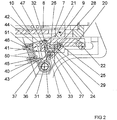
- FIG. 2 shows the trigger device 5 in detail.
- a catching piece 20 with a nose 21 above is by means of two at her rear end on both sides arranged stub 22 in grooves 23 of the housing longitudinally displaceable guided and swiveled around the stub 22.
- the catching piece 20 has one of bottom accessible recess 24, which is essentially a thrust surface 25th and a control surface 26 is limited, in which the one, bent, end 27 of the trigger bar 15 engages.
- a crosspiece 28 is provided, on which the first Leg 29 of a first spring 30 attacks and on this a forward-upward Exercise power.
- the first spring 30 is here a hairpin spring, the middle part of a Cross pin 31, which is also an axis, wraps around.
- At its front upper End of the catch piece has a nose 32. Under the nose 32 extends in the significant vertical chest area 33.
- a cylindrical pin 35 is fixedly arranged in the housing, it forms a threshold and to him the second leg 36 of the first spring 30 is supported.
- the threshold 35 acts with a Ramp 37 together, by a horizontal leg surface 38 and a formed with this an obtuse angle forming ascending leg surface 39 is.
- the obtuse angle is approximately equal to the angle of the interacting attack surfaces the nose 21 and the flag 9.
- a drag lever 40 is rotatably mounted about the housing-fixed pivot axis 31 and the Catch 20 upstream. It consists of one or two arms 41 and a bridge 42, to which the first leg 44 of a second spring 43 (here also a hairpin spring) acts. Its second leg 45 is located on a part of the housing 1, a housing wall 46 on. The rear upper end of the bridge 42 forms a crest edge 47, which in still too descriptive manner with the nose 32 cooperates.
- the housing wall 46 serves the drag lever 40 in its foremost position as a stop on which he is under can support the pressure of the striker.
- By another adjusting screw 50 in the housing wall 46 can act on the second leg of the second spring 43 be, whereby the trigger weight is adjustable. By adjusting the stop and thus the end position by means of a screw 51 can be the forward stroke on the trigger adjust.
- the device In the position of FIG. 2 , the device is ready to fire when the striker spring 8 is tensioned.
- the flag 9 is supported on the nose 21.
- the catching piece 20 lies on the one hand on the threshold 35 and therefore can not swing down and on the other hand in the longitudinal direction on the drag lever 40 at. Since the striking spring 8 is much stronger than the second spring 43, it overcomes their force and pushes the rocker arm 40 forward, where it rests against the housing wall 46 and the adjusting screw 51.
- the end 27 of the trigger rod 15 is located in the recess 24 and is located on the thrust surface 25 at. About the trigger guard 17, the entire trigger system is positively locked and secured against falls.
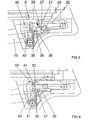
- the trigger rod 15, acting on the thrust surface 25, pushes the catching piece 20 backwards, against the force of the striking spring 8, but supported by the second spring 43.
- the catching piece 20 moves without pivoting to the rear. Only when the horizontal leg surface 38 merges into the ascending leg surface 39, the catching piece is pivoted downwards by the force of the striking spring 8 and the nose 21 releases the flag. This position can be seen in Fig.3 .
- the approximately parallel alignment of the ascending leg surface 39 and the engagement surface between the lug 21 and the lug 9 makes itself noticeable in an advantageous manner.
Landscapes
- Engineering & Computer Science (AREA)
- General Engineering & Computer Science (AREA)
- Portable Nailing Machines And Staplers (AREA)
- Preliminary Treatment Of Fibers (AREA)
Claims (8)
- Pistolet constitué d'une carcasse contenant un mécanisme de détente et d'une glissière qui coulisse sur celle-ci et qui contient le canon et la culasse, la culasse (4) étant dotée d'un pointeau percuteur (7) qui peut être entraíné par un ressort de percussion (8), et une détente (13) agissant par l'intermédiaire d'une tringle de détente (15) sur le mécanisme de détente (5) qui présente une pièce d'arrêt (20) qui s'engage par un bec (21) dans le parcours de déplacement du pointeau du percuteur, caractérisé en ce quea) la pièce d'arrêt (20) est guidée dans la carcasse (1) à coulissement dans le sens de la longueur et à pivotement vers le bas et est sollicitée vers le haut par un premier ressort (30),b) une traverse (35) fixe dans la carcasse est prévue et coopère avec une surface inclinée (37) de la pièce d'arrêt (20) de sorte que lors de l'actionnement de la détente, la pièce d'arrêt est d'abord déplacée dans le sens de la longueur et pivote vers le bas lorsqu'elle a dépassé la traverse,c) un levier d'entraínement (40) qui peut pivoter autour d'un axe fixe de la carcasse est prévu en avant de la pièce d'arrêt (20) et est sollicité vers l'arrière en direction de la pièce d'arrêt par un deuxième ressort (43), présente une arête de sommet (47) située à distance de son axe (31) et s'appuie contre la paroi (46) de la carcasse dans sa position avant etd) la pièce d'arrêt (20) présente à l'avant un petit bec (32) qui repose sur l'arête de sommet (47) du levier d'entraínement (40) lorsque la pièce d'arrêt et le levier d'entraínement se trouvent dans une position en arrière.
- Pistolet selon la revendication 1, caractérisé en ce que la traverse (35) fixée à la carcasse est configurée comme un tourillon de section transversale ronde et en ce que la surface inclinée (37) est formée par deux surfaces d'aile (38, 39) qui se rejoignent à angle obtus.
- Pistolet selon la revendication 2, caractérisé en ce que le pointeau percuteur (7) possède un talon (9) doté d'une surface d'engagement inclinée, en ce que le bec (21) de la pièce d'arrêt (20) présente une surface d'engagement inclinée, et en ce que l'angle d'inclinaison de ces deux surfaces d'engagement et de la deuxième surface d'aile (39) sont sensiblement égaux.
- Pistolet selon la revendication 3, caractérisé en ce que la pièce d'arrêt (20) possède un évidement (24) doté d'une surface de poussée (25) à l'arrière et d'une surface de commande (26) à l'avant, et l'extrémité (27) de la tringle de détente (15) qui coopère avec elle peut se placer sur la surface de poussée (25) de telle sorte que, lors d'un pivotement vers le bas de la pièce d'arrêt, l'extrémité (27) se dégage.
- Pistolet selon la revendication 1, caractérisé en ce que l'extrémité avant (27) de la tringle de détente (15) est articulée sur la détente (13) et en ce que la détente est dotée d'une sûreté de détente (17).
- Pistolet selon la revendication 1, caractérisé en ce que la force exercée par le deuxième ressort (43) par action sur sa deuxième branche (45) peut être ajustée au moyen d'une vis d'ajustement (50).
- Pistolet selon la revendication 1, caractérisé en ce que la force exercée par le deuxième ressort (43) est inférieure à la force du ressort de percussion (8).
- Pistolet selon la revendication 1, caractérisé en ce que le premier et/ou le deuxième ressort (30, 43) sont des ressorts en épingle à cheveux enfilés sur l'axe (31) du levier d'entraínement (40).
Priority Applications (1)
| Application Number | Priority Date | Filing Date | Title |
|---|---|---|---|
| AT99890171T ATE254753T1 (de) | 1998-07-14 | 1999-05-28 | Pistole mit vorgespanntem schlagbolzen |
Applications Claiming Priority (2)
| Application Number | Priority Date | Filing Date | Title |
|---|---|---|---|
| AT47998U | 1998-07-14 | ||
| AT0047998U AT3024U1 (de) | 1998-07-14 | 1998-07-14 | Pistole mit vorgespanntem schlagbolzen |
Publications (3)
| Publication Number | Publication Date |
|---|---|
| EP0973005A2 EP0973005A2 (fr) | 2000-01-19 |
| EP0973005A3 EP0973005A3 (fr) | 2001-03-07 |
| EP0973005B1 true EP0973005B1 (fr) | 2003-11-19 |
Family
ID=3491709
Family Applications (1)
| Application Number | Title | Priority Date | Filing Date |
|---|---|---|---|
| EP99890171A Expired - Lifetime EP0973005B1 (fr) | 1998-07-14 | 1999-05-28 | Pistolet comportant un percuteur préarmé |
Country Status (4)
| Country | Link |
|---|---|
| US (1) | US6263606B1 (fr) |
| EP (1) | EP0973005B1 (fr) |
| AT (2) | AT3024U1 (fr) |
| DE (1) | DE59907777D1 (fr) |
Families Citing this family (6)
| Publication number | Priority date | Publication date | Assignee | Title |
|---|---|---|---|---|
| DE102005031927B3 (de) * | 2005-07-08 | 2006-11-16 | Carl Walther Gmbh | Abzugs-Vorrichtung für Schusswaffen |
| DE102005031928B4 (de) * | 2005-07-08 | 2008-05-29 | Carl Walther Gmbh | Abzug-Vorrichtung mit Quick-Action-Funktion |
| DE102005031929B4 (de) * | 2005-07-08 | 2008-05-21 | Carl Walther Gmbh | Abzug-Vorrichtung mit Double-Action-Funktion |
| WO2013093571A2 (fr) * | 2011-12-23 | 2013-06-27 | Arsenal Firearms Finance Limited | Arme à feu |
| USD763974S1 (en) * | 2014-01-02 | 2016-08-16 | Htr Development, Llc | Firing bolt tip for use in a paint ball gun |
| CN115060111B (zh) * | 2022-06-16 | 2024-02-20 | 深圳市鑫创达安全设备制造有限公司 | 应用于手枪的战术扩展系统 |
Family Cites Families (10)
| Publication number | Priority date | Publication date | Assignee | Title |
|---|---|---|---|---|
| US2584299A (en) * | 1948-07-15 | 1952-02-05 | Olin Ind Inc | Fire-control mechanism for firearms |
| CH278319A (de) * | 1949-09-20 | 1951-10-15 | Hispaniola Corp La Hispaniola | Selbsttätige Feuerwaffe mit feststehendem Lauf. |
| CH297884A (fr) * | 1951-04-17 | 1954-04-15 | Gevarm Societe A Responsabilit | Carabine automatique. |
| US3027811A (en) * | 1958-04-29 | 1962-04-03 | Remington Arms Co Inc | Fire control mechanism for reciprocating bolt firearms |
| US3103758A (en) * | 1960-12-22 | 1963-09-17 | Wilhelm Gary | Firing mechanism for firearms |
| DE2311940C3 (de) * | 1973-03-09 | 1979-08-23 | J.G. Anschuetz Gmbh, 7900 Ulm | Abzugsvorrichtung für Schußwaffen, insbesondere für Wettkampf-Schußwaffen |
| MX159080A (es) | 1982-04-29 | 1989-04-14 | Gaston Glock | Mejoras a pistola |
| DE19507052A1 (de) | 1995-03-01 | 1996-09-05 | Walther Carl Gmbh | Abzugseinrichtung für Schußwaffen |
| EP0785404A3 (fr) * | 1996-01-19 | 1998-10-21 | SAM Lugano SA | Mécanisme de mise à feu pour libérer le percuteur d'une arme à feu lors du tir |
| US5906066A (en) * | 1997-11-17 | 1999-05-25 | Felk; Edward Karl | Automatic pistol mechanism |
-
1998
- 1998-07-14 AT AT0047998U patent/AT3024U1/de not_active IP Right Cessation
-
1999
- 1999-05-28 AT AT99890171T patent/ATE254753T1/de active
- 1999-05-28 EP EP99890171A patent/EP0973005B1/fr not_active Expired - Lifetime
- 1999-05-28 DE DE59907777T patent/DE59907777D1/de not_active Expired - Lifetime
- 1999-06-30 US US09/343,670 patent/US6263606B1/en not_active Expired - Lifetime
Also Published As
| Publication number | Publication date |
|---|---|
| US6263606B1 (en) | 2001-07-24 |
| ATE254753T1 (de) | 2003-12-15 |
| AT3024U1 (de) | 1999-08-25 |
| EP0973005A3 (fr) | 2001-03-07 |
| DE59907777D1 (de) | 2003-12-24 |
| EP0973005A2 (fr) | 2000-01-19 |
Similar Documents
| Publication | Publication Date | Title |
|---|---|---|
| AT507904B1 (de) | Prallschlagsicherung für eine schusswaffe | |
| DE19626077A1 (de) | Abzugseinrichtung | |
| EP0730135B1 (fr) | Mécanisme de détente pour armes à feu sans chien | |
| DE69409169T2 (de) | Abzugsmechanismus für Feuerwaffen | |
| EP1456597B1 (fr) | Dispositif de detente destine a une arme de poing automatique | |
| CH685262A5 (de) | Mit Spannabzug oder selbstspannende Feuerwaffe. | |
| DE10014687C1 (de) | Handfeuerwaffe mit Spannstücksicherung | |
| DE102004041054B3 (de) | Schlosssystem für eine mehrläufige Waffe | |
| AT409898B (de) | Abzugseinrichtung für ein gewehr | |
| DE1728249A1 (de) | Selbstladepistole mit Spannabzug | |
| WO2004072571A1 (fr) | Systeme de detente pour armes a feu de poing | |
| CH620763A5 (fr) | ||
| DE102007059097B3 (de) | Schlosssystem für eine mehrläufige Waffe | |
| EP0895053B1 (fr) | Mécanisme de mise à feu à double action | |
| EP0973005A2 (fr) | Pistolet comportant un percuteur préarmé | |
| EP4028708B1 (fr) | Système de verrouillage | |
| DE19605851C2 (de) | Sicherung eines Schlagbolzens einer Schlagbolzen- und Schlagstückeinrichtung für eine Schußwaffe | |
| EP1643203B1 (fr) | Système de détente pour armes à feu de poing | |
| DE2332273A1 (de) | Fangvorrichtung an einer selbsttaetigen feuerwaffe | |
| EP1597530B1 (fr) | Systeme de detente pour armes a feu de poing | |
| AT404511B (de) | Leichte sportpistole | |
| DE1453917A1 (de) | Zuschiessende automatische Handfeuerwaffe | |
| DE3625532C1 (en) | Weapon trigger for an automatic weapon | |
| DE19639692C1 (de) | Abzugseinrichtung mit Rückstecher | |
| DE59655C (de) | Mehrlade-Feuerwaffe mit durch einen Finger bewegbarem Cylinder-Verschlufs |
Legal Events
| Date | Code | Title | Description |
|---|---|---|---|
| PUAI | Public reference made under article 153(3) epc to a published international application that has entered the european phase |
Free format text: ORIGINAL CODE: 0009012 |
|
| AK | Designated contracting states |
Kind code of ref document: A2 Designated state(s): AT BE DE ES FR IT |
|
| AX | Request for extension of the european patent |
Free format text: AL;LT;LV;MK;RO;SI |
|
| PUAL | Search report despatched |
Free format text: ORIGINAL CODE: 0009013 |
|
| AK | Designated contracting states |
Kind code of ref document: A3 Designated state(s): AT BE CH CY DE DK ES FI FR GB GR IE IT LI LU MC NL PT SE |
|
| AX | Request for extension of the european patent |
Free format text: AL;LT;LV;MK;RO;SI |
|
| 17P | Request for examination filed |
Effective date: 20010330 |
|
| AKX | Designation fees paid |
Free format text: AT BE DE ES FR IT |
|
| RAP1 | Party data changed (applicant data changed or rights of an application transferred) |
Owner name: STEYR MANNLICHER GMBH & CO. KG |
|
| GRAH | Despatch of communication of intention to grant a patent |
Free format text: ORIGINAL CODE: EPIDOS IGRA |
|
| GRAS | Grant fee paid |
Free format text: ORIGINAL CODE: EPIDOSNIGR3 |
|
| GRAA | (expected) grant |
Free format text: ORIGINAL CODE: 0009210 |
|
| RAP1 | Party data changed (applicant data changed or rights of an application transferred) |
Owner name: STEYR MANNLICHER HOLDING GMBH |
|
| AK | Designated contracting states |
Kind code of ref document: B1 Designated state(s): AT BE DE ES FR IT |
|
| PG25 | Lapsed in a contracting state [announced via postgrant information from national office to epo] |
Ref country code: FR Free format text: LAPSE BECAUSE OF FAILURE TO SUBMIT A TRANSLATION OF THE DESCRIPTION OR TO PAY THE FEE WITHIN THE PRESCRIBED TIME-LIMIT Effective date: 20031119 |
|
| REF | Corresponds to: |
Ref document number: 59907777 Country of ref document: DE Date of ref document: 20031224 Kind code of ref document: P |
|
| PG25 | Lapsed in a contracting state [announced via postgrant information from national office to epo] |
Ref country code: ES Free format text: LAPSE BECAUSE OF FAILURE TO SUBMIT A TRANSLATION OF THE DESCRIPTION OR TO PAY THE FEE WITHIN THE PRESCRIBED TIME-LIMIT Effective date: 20040302 |
|
| PLBE | No opposition filed within time limit |
Free format text: ORIGINAL CODE: 0009261 |
|
| STAA | Information on the status of an ep patent application or granted ep patent |
Free format text: STATUS: NO OPPOSITION FILED WITHIN TIME LIMIT |
|
| 26N | No opposition filed |
Effective date: 20040820 |
|
| EN | Fr: translation not filed | ||
| REG | Reference to a national code |
Ref country code: DE Ref legal event code: R082 Ref document number: 59907777 Country of ref document: DE Representative=s name: V. FUENER EBBINGHAUS FINCK HANO, DE Effective date: 20131128 Ref country code: DE Ref legal event code: R081 Ref document number: 59907777 Country of ref document: DE Owner name: STEYR MANNLICHER GMBH, AT Free format text: FORMER OWNER: STEYR MANNLICHER HOLDING GMBH, WIENER NEUSTADT, AT Effective date: 20131128 |
|
| PGFP | Annual fee paid to national office [announced via postgrant information from national office to epo] |
Ref country code: DE Payment date: 20180522 Year of fee payment: 20 |
|
| PGFP | Annual fee paid to national office [announced via postgrant information from national office to epo] |
Ref country code: AT Payment date: 20180522 Year of fee payment: 20 Ref country code: IT Payment date: 20180530 Year of fee payment: 20 Ref country code: BE Payment date: 20180518 Year of fee payment: 20 |
|
| REG | Reference to a national code |
Ref country code: DE Ref legal event code: R071 Ref document number: 59907777 Country of ref document: DE |
|
| REG | Reference to a national code |
Ref country code: BE Ref legal event code: MK Effective date: 20190528 |
|
| REG | Reference to a national code |
Ref country code: AT Ref legal event code: MK07 Ref document number: 254753 Country of ref document: AT Kind code of ref document: T Effective date: 20190528 |