EP0973032B1 - System zur Probenahme spezifischer Verunreinigungen, die sich in verdünnten Abgasen von thermischen Maschinen befinden - Google Patents
System zur Probenahme spezifischer Verunreinigungen, die sich in verdünnten Abgasen von thermischen Maschinen befinden Download PDFInfo
- Publication number
- EP0973032B1 EP0973032B1 EP99401452A EP99401452A EP0973032B1 EP 0973032 B1 EP0973032 B1 EP 0973032B1 EP 99401452 A EP99401452 A EP 99401452A EP 99401452 A EP99401452 A EP 99401452A EP 0973032 B1 EP0973032 B1 EP 0973032B1
- Authority
- EP
- European Patent Office
- Prior art keywords
- path
- gases
- solenoid valve
- circuit
- diluted
- Prior art date
- Legal status (The legal status is an assumption and is not a legal conclusion. Google has not performed a legal analysis and makes no representation as to the accuracy of the status listed.)
- Expired - Lifetime
Links
Images

Classifications
-
- G—PHYSICS
- G01—MEASURING; TESTING
- G01N—INVESTIGATING OR ANALYSING MATERIALS BY DETERMINING THEIR CHEMICAL OR PHYSICAL PROPERTIES
- G01N33/00—Investigating or analysing materials by specific methods not covered by groups G01N1/00 - G01N31/00
- G01N33/0004—Gaseous mixtures, e.g. polluted air
- G01N33/0009—General constructional details of gas analysers, e.g. portable test equipment
- G01N33/0027—General constructional details of gas analysers, e.g. portable test equipment concerning the detector
- G01N33/0036—General constructional details of gas analysers, e.g. portable test equipment concerning the detector specially adapted to detect a particular component
- G01N33/0047—Organic compounds
-
- G—PHYSICS
- G01—MEASURING; TESTING
- G01N—INVESTIGATING OR ANALYSING MATERIALS BY DETERMINING THEIR CHEMICAL OR PHYSICAL PROPERTIES
- G01N33/00—Investigating or analysing materials by specific methods not covered by groups G01N1/00 - G01N31/00
- G01N33/0004—Gaseous mixtures, e.g. polluted air
- G01N33/0009—General constructional details of gas analysers, e.g. portable test equipment
- G01N33/0022—General constructional details of gas analysers, e.g. portable test equipment using a number of analysing channels
-
- G—PHYSICS
- G01—MEASURING; TESTING
- G01N—INVESTIGATING OR ANALYSING MATERIALS BY DETERMINING THEIR CHEMICAL OR PHYSICAL PROPERTIES
- G01N33/00—Investigating or analysing materials by specific methods not covered by groups G01N1/00 - G01N31/00
- G01N33/0004—Gaseous mixtures, e.g. polluted air
- G01N33/0009—General constructional details of gas analysers, e.g. portable test equipment
- G01N33/0011—Sample conditioning
- G01N33/0018—Sample conditioning by diluting a gas
Definitions
- the present invention relates to the field of the sampling of gaseous fluids for their analysis, such as the exhaust gases of thermal combustion machines.
- the present invention relates to the collection of gaseous fluids containing aldehydes and ketones as well as hydrocarbons.
- these two sampling modes can be performed simultaneously or not, depending on a chosen analytical objective.
- An advantageous use of the invention relates to the exhaust gas sampling of motor vehicles operating on dynamic chassis during standardized driving cycles.
- the present invention is designed to automatically provide, during a predetermined driving cycle, several samples associated with specific phases of operation of the vehicle.
- JP 63 132 161 describes an analysis system with two channels, one for alcohols and the other for formaldehyde.
- dinitrophenylhydrazine grafted silica cartridges that make it possible to chemically collect and derive hydrazone compounds from these chemical species are currently the most commonly used. Each cartridge must then undergo treatment at the analytical laboratory to dissolve these compounds in a solvent (acetonitrile). This sampling technique has the advantage of being efficient, easy to use and offers medium-term storage possibilities for samples.
- the hydrazone derivatives are then separated by injecting an aliquot of this solution into a chromatography HPLC (High Performance Liquid Chromatography) array and individually detected by UV (ultraviolet) absorption.
- HPLC High Performance Liquid Chromatography
- the present invention allows this type of sampling.
- the present invention allows in particular the use of known cartridges, their quick and waterproof installation in a suitable sampling medium eliminating any external pollution, the simple programming of the sampling parameters, the complete automaticity of the sampling when the order is given of start the trapping of the effluents according to the operating phase of the vehicle.
- the present invention allows a permanent control of the sampling conditions during the operating cycle (flow rates, temperatures, trapping time).
- the present invention allows a modular, automated and interactive sampling of the gases emitted by a thermal machine in operation.
- the subject of the present invention is a system for sampling specific pollutants contained in diluted exhaust gases from combustion combustion machines, comprising a first module dedicated to emissions of aldehydes and ketones and a second module intended for hydrocarbon emissions. .
- the system further comprises means for coordinating said sampling (s) at predetermined operating phases of said thermal machine.
- the first module may further comprise a purge circuit for cleaning the circuits carrying the diluted gases and the dilution air before they enter the sampling module itself.
- the trapping circuit of aldehydes and ketones comprises at least one sampling cartridge disposed in a sampling path.
- a solenoid valve may be placed downstream of each sampling cartridge, allowing either the passage of gas downstream, or the obstruction of the corresponding channel.
- the purge circuit comprises a general inlet for the purge gas, and two parallel tracks, one associated with the trapped diluted exhaust gas circuit, the other with the trapping circuit of the exhaust air. dilution, the two paths opening at one end on the general arrival of the purge gas and on the other end either on the arrival of the diluted gases, or on the arrival of the dilution air.
- each channel of the purge circuit comprises a solenoid valve disposed near the general inlet of the purge gas, making it possible to cut off the circulation in the channel, and an element intended to fix the flow rate of the purge gas in the channel.
- the second processing means may comprise a circuit intended to purge one or more of the gas sampling bags that it contains per emptying / filling cycle.
- said purge circuit comprises a general inlet for the purge gas, a first solenoid valve connected to a pump, a second solenoid valve, an evacuation and a connection circuit to the parallel channels.
- the first solenoid valve is connected to the general inlet, the pump and the connecting circuit to the parallel channels.
- the second solenoid valve is connected to the general evacuation, the pump and the connecting circuit to the parallel channels.
- the purge circuit further comprises a filter disposed between the second solenoid valve and the parallel channels associated with the bags, said filter being intended to purify the air during gas filling cycles.
- the means for directing the exhaust gas comprises a solenoid valve placed on the gas flow path, a solenoid valve on the (or each) way equipped with a sampling bag and a solenoid valve upstream of said parallel channels.
- the means for directing the dilution air comprises a solenoid valve placed on the air flow path, a solenoid valve on the (or each) path equipped with a sampling bag and a solenoid valve upstream of said parallel tracks.
- the second hydrocarbon sampling module comprises two parallel tracks at the level of the general inlet of the diluted gases, one for diesel engine gases and the other for ignition engine gases. ordered.
- the path for the diesel exhaust includes a heated filter and an element for setting the mass flow rate of the gas to be withdrawn, while the other path includes an element for setting the mass flow rate of the gas to be withdrawn and a filter for impurities.
- the system comprises, upstream of parallel channels for sampling diluted gases, a pump and a flow meter.
- the dilution air supply line comprises, upstream of the parallel channels, a filter, a pump and an adjustable flowmeter.
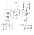
- the figure 1 schematizes the module 1 for sampling the aldehydes and ketones according to the invention.
- a circuit 3 for trapping aldehydes and ketones constituted by a general inlet 30 for said diluted gases, which separates into a plurality of parallel channels: one comprises a means 31 for taking aldehydes and ketones (such as a Sep Pak Silica water cartridge for example), and a solenoid valve 32 for stopping the flow in each channel; another parallel channel is intended for simulating the passage of gases in the other channels and it comprises a filter 33 and a solenoid valve 34.
- All of these parallel paths have a common output on a single path which may include a filter 35, a mass flow controller 36 and a pump 37 arranged in series.
- the first module 1 comprises a second general inlet 40 of a circuit 4 for sampling the dilution air which serves to dilute the gases.
- the circuit 4 is generally organized as the circuit 3, that is to say that it comprises several parallel paths having the general input 40 in common.
- Several channels (here three in number) allow the dilution air to be sampled, with a cartridge 41 and an associated solenoid valve 42, downstream of the cartridge 41.
- Another channel allows the simulation of the passage of gases in the air channels. sample ; this way generally comprises a filter 43 in series with a solenoid valve 44. This way makes it possible to circulate the diluted gases when it is not considered useful to circulate them in the sampling channels proper.
- the control of the different solenoid valves allows this selective distribution.
- the common (unreferenced) output of the parallel channels is connected to the input of a single channel which preferably comprises a filter 45, a mass flow controller 46 and a pump 47.
- the sampling module 1 thus provides a sampling of the dilution air and diluted gases which allows a subsequent determination of the undiluted gas composition.
- the module 1 may comprise a purge circuit 6 which, once all the samples taken at the level of the module 1, purge the arrivals of the diluted gases and the dilution air against the current.
- a purge gas for example nitrogen, is fed to a general inlet 61 which separates into two conduits 62, 63: one 62 opening towards the arrival 40 of the dilution air while the second conduit 62 63 opens at the general arrival of the diluted gas 30.
- Each conduit 62, 63 comprises a solenoid valve 66, 67 and a means 64, 65 for fixing the flow rate of the purge gas; this means can be a capillary for example.
- the dilution air and the diluted gases are heated before entering the first module, for example by heating rods.
- the figure 2 schematizes the main elements of the hydrocarbon sampling module 2 which comprises a first set 21 for the diluted gases and a second set 8 for the dilution air. Additionally and not necessarily, a third set 7 may be considered, to drain the elements that have been filled with gas.
- the assembly 21 comprises at least one general inlet for the diluted gases.
- the assembly 21 there are two separate entries; one G1 for diesel engine exhaust and the other G2 for gasoline engine exhaust. Of course this is quite optional but it allows to best treat each type of vehicle exhaust.
- the gases from G1 pass through a heated filter holder 22 and a calibrated orifice 23; heating avoids hydrocarbon retention; the gases from G2 pass through a calibrated orifice 24 first and then a filter 25 for retaining the large impurities (agglomerates) possibly contained in the exhaust gas.
- the two parallel tracks G1, G2 meet at a valve 26 at the end of a transfer channel here equipped with a pump 28, a flow meter 27, and a solenoid valve 29.
- the transfer route leads to a common entrance for several parallel tracks: here three parallel routes are provided for the removal of hydrocarbons from the diluted gas; a fourth lane is also provided for a flow of gas before any sampling.
- the gas flow path includes a solenoid valve 50 to adjust the flow prior to sampling.
- the three parallel channels are each equipped with a solenoid valve 51 and a bag 52 for collecting the gases.
- the number of lanes equipped with sampling bags 52 is not necessarily equal to three. Only one way or more can be envisaged without departing from the scope of the invention.
- solenoid valves 29, 50 and 51 which appear in the embodiment of the invention illustrated by the figure 2 may be replaced by any means known in itself, without departing from the scope of the invention, for distributing and selectively orienting the diluted gases to the driving lane or one of the lanes equipped with bag 52.
- the second set 8 of the hydrocarbon sampling module 2 relates to the dilution air which arrives on a filter 53 and then on a pump 55 connected to a solenoid valve 56 and an adjustable flowmeter 54; all these elements are in series on the dilution line which leads to a common input to several parallel channels.
- One of the channels comprises only a solenoid valve 57 and is intended to pass the dilution air before or after the actual sampling phase.
- the other parallel paths here three in number, each comprise a solenoid valve 58 and a sampling bag 59.
- solenoid valves 56, 57 and 58 may be replaced by any other means for selectively directing the dilution air towards the circulation lane or to one of the lanes equipped with bags 59.
- the module 2 may comprise a system 7 for emptying and filling the sampling bags 52, 59.
- evacuation mode the bags will be emptied of the outside air which filled them beforehand (during the filling phase). This procedure, optional, allows to reuse the same bags for several sampling campaigns.
- the system 7 comprises an outside air supply line 71 which, in filling mode, passes through a first solenoid valve 72, a pump 73, a second solenoid valve 74 and then a filter 75 which purifies the air during the rinsing cycles. .
- the outside air is then separated in two: a part is directed towards the solenoid valve 56 on the dilution air side if the bags 59 are to be cleaned; another portion of the outside air is directed to the solenoid valve 29 if the dilute gas sampling bags 52 are to be cleaned.
- Each solenoid valve 29, 56 controlled by a central system allows or not the passage of outside air.
- the air contained in the bags is evacuated by making the following path: it passes into the first solenoid valve 12 and then into the pump 73 and the second solenoid valve 74, to finally exit by a specific line 76.
- the assembly that has just been described further comprises a control of the different solenoid valves and other active elements, so that the sample or samples are made depending eg on the operating phase of the vehicle that emits exhaust gas.
- a control unit as schematized on the figure 3 is provided for this purpose.
- This command management unit is made up of a programmable logic controller which makes it possible to memorize all the sampling parameters during the operating cycle, to provide interactive control with the dynamometer installations and to activate with respect to its initial programming the different elements constituting the sampling circuits (pumps, solenoid valves ).
- the means CM represents the device which ensures the control of the thermal machine, including all the parameters characterizing a phase of its operation.
- the means CM sends appropriate control signals to a control means CCA of the first module 1, as well as signals to a control means CCH of the second module 2.
- the samples stored on the solid supports (cartridge type 31, 41) or in sampling bags 52, 59 are brought into an analysis laboratory where their chromatographic analysis allows the quantification of the aldehydes present. in both the dilution air and the diluted gas, from which a determination of the amount of pollutants in undiluted gases is made.
Landscapes
- Chemical & Material Sciences (AREA)
- Life Sciences & Earth Sciences (AREA)
- Engineering & Computer Science (AREA)
- Health & Medical Sciences (AREA)
- Analytical Chemistry (AREA)
- Food Science & Technology (AREA)
- Medicinal Chemistry (AREA)
- Physics & Mathematics (AREA)
- Combustion & Propulsion (AREA)
- Biochemistry (AREA)
- General Health & Medical Sciences (AREA)
- General Physics & Mathematics (AREA)
- Immunology (AREA)
- Pathology (AREA)
- Sampling And Sample Adjustment (AREA)
- Investigating Or Analyzing Materials Using Thermal Means (AREA)
Claims (20)
- System zur Entnahme von spezifischen Schadstoffen, die in verdünnten Abgasen enthalten sind, die aus Verbrennungskraftmaschinen kommen, umfassend eine erste Einheit (1) für Aldehyd- und Ketonemissionen und eine zweite Einheit (2) zur Entnahme von Kohlenwasserstoffemissionen, dadurch gekennzeichnet, dass es außerdem ein Mittel umfasst, um die Entnahme(n) in vorherbestimmten Betriebsphasen der Kraftmaschine zu koordinieren.
- Entnahme- und Messsystem nach Anspruch 1, dadurch gekennzeichnet, dass die erste Einheit (1) folgendes umfasst:- einen Kreislauf (3) zum Einfangen der Aldehyde und Ketonen, die in den verdünnten Abgasen enthalten sind, umfassend einen Kanal zum Simulieren des Gasdurchgangs, der parallel zu mindestens einem Kanal zur Entnahme des verdünnten Gases angeordnet ist, wobei diese Kanäle einen gemeinsamen Eingang (30) für die verdünnten Gase und einen gemeinsamen Ausgang haben, der mit einer Leitung verbunden ist, die ein Filterelement (35), einen Massenstromregler (36) und eine Pumpe (37), die in Reihe geschaltet sind, umfasst;- einen Kreislauf (4) zur Entnahme der Verdünnungsluft, umfassend einen Kanal zum Simulieren des Gasdurchgangs, der parallel zu mindestens einem Kanal zur Entnahme der Verdünnungsluft angeordnet ist, wobei diese Kanäle einen gemeinsamen Eingang (40) für die Verdünnungsluft und einen gemeinsamen Ausgang haben, der mit einer Leitung verbunden ist, die ein Filterelement (45), einen Massenstromregler (46) und eine Pumpe (47), die in Reihe geschaltet sind, umfasst.
- System nach Anspruch 2, dadurch gekennzeichnet, dass die erste Einheit (1) außerdem einen Entlüftungskreislauf (6) umfasst, der dazu gedacht ist, die Kreisläufe zu reinigen, welche die verdünnten Gase und die Verdünnungsluft vor ihrem Eintritt in die Entnahmeeinheit (1) selber transportiert haben.
- System nach einem der vorhergehenden Ansprüche, dadurch gekennzeichnet, dass der Kreislauf zum Einfangen der Aldehyde und Ketonen mindestens einen Entnahmeeinsatz (31) umfasst, der in einem Entnahmekanal angeordnet ist.
- System nach Anspruch 4, dadurch gekennzeichnet, dass ein Magnetventil (32) unterhalb jedes Entnahmeeinsatzes (31) eingesetzt ist, das entweder den Durchgang der Gase nach unten oder die Versperrung des entsprechenden Kanals ermöglicht.
- System nach einem der Ansprüche 3 bis 5, dadurch gekennzeichnet, dass der Entlüftungskreislauf (6) eine Hauptzuführung (61) für das Entlüftungsgas und zwei Parallelkanäle (62, 63) umfasst, wobei der eine zum Kreislauf (3) zum Einfangen der verdünnten Entlüftungsgase und der andere zum Kreislauf (4) zum Einfangen der Verdünnungsluft gehört, wobei die beiden Kanäle über das eine Ende an der Hauptzuführung (61) des Entlüftungsgases und über das andere Ende entweder an der Zuführung (30) der verdünnten Gase oder an der Zuführung (40) der Verdünnungsluft ausmünden.
- System nach Anspruch 6, dadurch gekennzeichnet, dass jeder Kanal (62, 63) des Entlüftungskreislaufs (6) ein Magnetventil (66, 67), das in der Nähe der Hauptzuführung (61) des Entlüftungsgases angeordnet ist, wodurch der Umlauf im Kanal abgeschaltet werden kann, und ein Element (64, 65), das dazu gedacht ist, den Durchfluss des Entlüftungsgases im Kanal (62, 63) festzusetzen, umfasst.
- System nach einem der vorhergehenden Ansprüche, dadurch gekennzeichnet, dass die zweite Einheit (2), die zur Kohlenwasserstoffentnahme gedacht ist, folgendes umfasst:- mindestens einen Haupteingang für die verdünnten Abgase (G1, G2), mindestens einen ersten Kanal, der mit einem Entnahmebeutel (52) ausgestattet ist, und einen anderen Kanal, der zum ersten Kanal parallel ist und den Umlauf der Gase außerhalb des Entnahmebeutels ermöglicht;- ein Mittel zur wahlweisen Orientierung der Abgase auf den einen oder anderen Kanal;- einen Haupteingang für die Verdünnungsluft, mindestens einen Kanal, der mit einem Entnahmebeutel (59) ausgestattet ist, und einen anderen Kanal, der den Umlauf von Verdünnungsluft außerhalb des Entnahmebeutels ermöglicht;- ein Mittel zur wahlweisen Orientierung der Verdünnungsluft zum einen oder anderen Kanal.
- System nach Anspruch 8, dadurch gekennzeichnet, dass das zweite Verarbeitungsmittel außerdem einen Kreislauf (7) umfasst, der dazu gedacht ist, einen oder mehrere der Entnahmebeutel (52, 59) des Gases, das er enthält, pro Entleerungs-/Füllungszyklus zu entlüften.
- System nach Anspruch 9, dadurch gekennzeichnet, dass der Entlüftungskreislauf (7) einen Haupteintritt (71) für das Entlüftungsgas, ein erstes Magnetventil (72), das mit einer Pumpe (73) verbunden ist, ein zweites Magnetventil (74), einen Ablass (76) und einen Verbindungskreislauf zu den Parallelkanälen umfasst.
- System nach Anspruch 10, dadurch gekennzeichnet, dass das erste Magnetventil (72) mit dem Haupteingang (71), der Pumpe (73) und dem Verbindungskreislauf zu den Parallelkanälen verbunden ist.
- System nach einem der Ansprüche 10 oder 11, dadurch gekennzeichnet, dass das zweite Magnetventil (74) mit dem Hauptablass (76), der Pumpe (73) und dem Verbindungskreislauf zu den Parallelkanälen verbunden ist.
- System nach einem der Ansprüche 9 bis 12, dadurch gekennzeichnet, dass der Entlüftungskreislauf (7) außerdem einen Filter (75) umfasst, der zwischen dem zweiten Magnetventil (74) und den zu den Beuteln gehörenden Parallelkanälen angeordnet ist, wobei der Filter (75) dazu gedacht ist, die Luft Während der Befüllungszyklen der Beutel zu säubern.
- System nach einem der Ansprüche 8 bis 13, dadurch gekennzeichnet, dass das Mittel zum Orientieren der Abgase ein Magnetventil (50), das in den Gasumlaufkanal gesetzt ist, und ein Magnetventil (51) in dem (bzw. jedem) Kanal, der mit einem Entnahmebeutel ausgestattet ist, und ein Magnetventil (29) oberhalb der Parallelkanäle umfasst.
- System nach einem der Ansprüche 8 bis 14, dadurch gekennzeichnet, dass das Mittel zum Orientieren der Verdünnungsluft ein Magnetventil (57), das in den Luftumlaufkanal gesetzt ist, ein Magnetventil (58) in dem (bzw. jedem) Kanal, der mit einem Entnahmebeutel ausgestattet ist, und ein Magnetventil (56) oberhalb der Parallelkanäle umfasst.
- System nach einem der Ansprüche 8 bis 15, dadurch gekennzeichnet, dass die zweite Einheit (2) zur Entnahme der Kohlenwasserstoffe zwei Parallelkanäle (G1, G2) am Haupteingang der verdünnten Gase umfasst, wobei der eine (G1) für die Gase von Dieselmotoren und der andere (G2) für die Gase von Motoren mit Funkenzündung bestimmt ist.
- System nach Anspruch 16, dadurch gekennzeichnet, dass der Kanal für die Dieselabgase einen beheizten Filter (22) und ein Element (23), das dazu gedacht ist, den Massenstrom des zu entnehmenden Gases festzulegen, umfasst.
- System nach einem der Ansprüche 16 oder 17, dadurch gekennzeichnet, dass der Kanal für die Abgase von Motoren mit Funkenzündung ein Element (24), das dazu gedacht ist, den Massenstrom des zu entnehmenden Gases festzulegen, und einen Filter (25) für die Verunreinigungen umfasst.
- System nach einem der Ansprüche 16 bis 18, dadurch gekennzeichnet, dass es außerdem oberhalb der Parallelkanäle für die Entnahme der verdünnten Gase eine Pumpe (28) und einen Durchflussmesser (27) umfasst.
- System nach einem der Ansprüche 8 bis 19, dadurch gekennzeichnet, dass die Leitung zur Versorgung mit Verdünnungsluft oberhalb der Parallelkanäle einen Filter (53), eine Pumpe (55) und einen einstellbaren Durchflussmesser (54) umfasst.
Applications Claiming Priority (2)
| Application Number | Priority Date | Filing Date | Title |
|---|---|---|---|
| FR9808198A FR2780507B1 (fr) | 1998-06-26 | 1998-06-26 | Systeme de prelevement de polluants specifiques contenus dans des gaz d'echappement dilues issus de machines thermiques |
| FR9808198 | 1998-06-26 |
Publications (2)
| Publication Number | Publication Date |
|---|---|
| EP0973032A1 EP0973032A1 (de) | 2000-01-19 |
| EP0973032B1 true EP0973032B1 (de) | 2008-05-28 |
Family
ID=9527965
Family Applications (1)
| Application Number | Title | Priority Date | Filing Date |
|---|---|---|---|
| EP99401452A Expired - Lifetime EP0973032B1 (de) | 1998-06-26 | 1999-06-14 | System zur Probenahme spezifischer Verunreinigungen, die sich in verdünnten Abgasen von thermischen Maschinen befinden |
Country Status (6)
| Country | Link |
|---|---|
| US (1) | US6134942A (de) |
| EP (1) | EP0973032B1 (de) |
| JP (1) | JP4262361B2 (de) |
| AT (1) | ATE397211T1 (de) |
| DE (1) | DE69938808D1 (de) |
| FR (1) | FR2780507B1 (de) |
Families Citing this family (18)
| Publication number | Priority date | Publication date | Assignee | Title |
|---|---|---|---|---|
| FR2780506B1 (fr) * | 1998-06-25 | 2000-08-25 | Inst Francais Du Petrole | Procede et unite de prelevement d'aldehydes et cetones contenus dans des gaz d'echappement |
| FR2812395B1 (fr) * | 2000-07-31 | 2003-01-10 | Bp Chemicals Snc | Procede et dispositif pour l'analyse d'emission atmospheriques |
| AT4978U1 (de) * | 2000-11-22 | 2002-01-25 | Avl List Gmbh | Verfahren zur konditionierung der ansaugluft sowie des abgasdrucks einer verbrennungsmaschine |
| AUPR600701A0 (en) * | 2001-06-28 | 2001-07-26 | Commonwealth Scientific And Industrial Research Organisation | Method and apparatus for measuring a property of air |
| US6823268B2 (en) * | 2002-02-04 | 2004-11-23 | Avl North America Inc. | Engine exhaust emissions measurement correction |
| US7555928B2 (en) * | 2002-12-05 | 2009-07-07 | Avl North America Inc. | Exhaust volume measurement device |
| FR2862386B1 (fr) * | 2003-11-14 | 2006-03-03 | Inst Francais Du Petrole | Procede et dispositif pour prelever des composes gazeux contenus dans un courant gazeux, notamment dans des gaz d'echappement dilues d'un moteur a combustion interne |
| AT7030U3 (de) * | 2004-04-08 | 2005-03-25 | Avl List Gmbh | Gasregelsystem |
| AT7031U3 (de) * | 2004-04-08 | 2005-03-25 | Avl List Gmbh | Gasregelmodul sowie verfahren zur durchflussregelung |
| JP4815438B2 (ja) * | 2004-07-21 | 2011-11-16 | センサーズ インコーポレイテッド | 収集排気ガス分析のための希釈流量制御システムとその方法 |
| US8181543B2 (en) | 2006-09-15 | 2012-05-22 | Avl North America Inc. | CVS system sample water vapor management |
| US7523641B2 (en) * | 2006-10-11 | 2009-04-28 | Juon Co., Ltd. | Method to measure exhaust-gas components |
| US7775219B2 (en) * | 2006-12-29 | 2010-08-17 | Applied Materials, Inc. | Process chamber lid and controlled exhaust |
| FR2922601A1 (fr) * | 2007-10-19 | 2009-04-24 | Inst Francais Du Petrole | Systeme de prelevement de gaz d'echappement recircules d'un moteur a combustion interne, en particulier de type diesel, et procede pour utiliser un tel systeme |
| US8505395B2 (en) * | 2009-08-25 | 2013-08-13 | Caterpillar Inc. | Dilution system test apparatus with added capability and method of operating same |
| JP5492001B2 (ja) * | 2010-07-23 | 2014-05-14 | 株式会社堀場製作所 | 排ガス分析システム |
| US9297726B2 (en) | 2012-05-23 | 2016-03-29 | Avl Test Systems, Inc. | Exhaust sampling system and method for water vapor management |
| CN104380077B (zh) | 2012-05-29 | 2018-03-27 | Avl测试系统公司 | 用于排气取样系统的智能袋填充 |
Family Cites Families (11)
| Publication number | Priority date | Publication date | Assignee | Title |
|---|---|---|---|---|
| US3406562A (en) * | 1966-01-14 | 1968-10-22 | Gen Motors Corp | On-line exhaust data analysis system |
| US4758521A (en) * | 1985-02-15 | 1988-07-19 | Union Carbide Corporation | Assay of ketones in ambient air |
| US4759210A (en) * | 1986-06-06 | 1988-07-26 | Microsensor Systems, Inc. | Apparatus for gas-monitoring and method of conducting same |
| DE3619301A1 (de) * | 1986-06-07 | 1987-12-10 | Ruhrgas Ag | Verfahren und einrichtung zur messung der aldehydkonzentration in abgasen |
| JPH07107533B2 (ja) * | 1986-11-21 | 1995-11-15 | 工業技術院長 | 自動車排気ガス分析装置 |
| JPH03232516A (ja) * | 1990-02-08 | 1991-10-16 | Nissan Motor Co Ltd | 自動車排出ガス中のアルデヒドの簡易捕集装置 |
| US5599357A (en) * | 1990-07-13 | 1997-02-04 | Ehtyl Corporation | Method of operating a refinery to reduce atmospheric pollution |
| JPH0545284A (ja) * | 1991-08-17 | 1993-02-23 | Horiba Ltd | パーテイキユレート連続分析装置 |
| JP3187541B2 (ja) * | 1992-07-15 | 2001-07-11 | 本田技研工業株式会社 | 排気ガス測定装置の診断方法 |
| US5498279A (en) * | 1994-05-13 | 1996-03-12 | Chromatofast | High speed gas chromatography system for analysis of polar organic compounds |
| DE19607574A1 (de) * | 1996-02-29 | 1997-09-04 | Siemens Ag | Verfahren und Vorrichtung zur Abgasmessung bei Verbrennungsmotoren, die mit Alkohol enthaltendem Kraftstoff betrieben werden |
-
1998
- 1998-06-26 FR FR9808198A patent/FR2780507B1/fr not_active Expired - Fee Related
-
1999
- 1999-06-14 AT AT99401452T patent/ATE397211T1/de active
- 1999-06-14 EP EP99401452A patent/EP0973032B1/de not_active Expired - Lifetime
- 1999-06-14 DE DE69938808T patent/DE69938808D1/de not_active Expired - Lifetime
- 1999-06-22 US US09/337,261 patent/US6134942A/en not_active Expired - Fee Related
- 1999-06-28 JP JP18146499A patent/JP4262361B2/ja not_active Expired - Fee Related
Also Published As
| Publication number | Publication date |
|---|---|
| EP0973032A1 (de) | 2000-01-19 |
| FR2780507B1 (fr) | 2000-09-01 |
| US6134942A (en) | 2000-10-24 |
| ATE397211T1 (de) | 2008-06-15 |
| JP2000028498A (ja) | 2000-01-28 |
| DE69938808D1 (de) | 2008-07-10 |
| JP4262361B2 (ja) | 2009-05-13 |
| FR2780507A1 (fr) | 1999-12-31 |
Similar Documents
| Publication | Publication Date | Title |
|---|---|---|
| EP0973032B1 (de) | System zur Probenahme spezifischer Verunreinigungen, die sich in verdünnten Abgasen von thermischen Maschinen befinden | |
| FR2558521A1 (fr) | Appareil de detection de gaz dans les puits souterrains | |
| JP2001501303A (ja) | ガスクロマトグラフのための分析エンジン | |
| EP0169469A2 (de) | Analysegerät | |
| FR2521299A1 (fr) | Procede et appareil pour l'analyse par chromatographie ionique d'anions. | |
| FR2563007A1 (fr) | Procede et appareil pour le dosage d'un microconstituant | |
| CA2296194C (fr) | Procede et dispositif d'analyse integree pour la caracterisation d'hydrocarbures, par simulation de distillation | |
| JP2001194354A (ja) | ガス・クロマトグラフィによる試料の分析方法および分析装置 | |
| FR2779824A1 (fr) | Installation d'analyse d'atmosphere | |
| JP3492192B2 (ja) | ガスクロマトグラフィの試料供給方法及び装置 | |
| US20010007224A1 (en) | Chromatograph having a gas storage system | |
| EP0967473B1 (de) | Verfahren und Vorrichtung zur Entnahme von Aldehyden und Ketonen in Abgasen | |
| EP1266211B1 (de) | Verbesserte vorrichtung zur probenanalyse durch multikapillar-elektrophorese mit festkörper/festkörper-thermoregulierung | |
| EP1859263A1 (de) | Gemischtes chromatographieverfahren mit superkritischer phase und einrichtung zur durchführung davon | |
| CA1078215A (en) | Fluid sample dilution for chromatographic analysis | |
| US3352089A (en) | Method and apparatus for introducing samples into a gas chromatographic column | |
| FR2599152A1 (fr) | Procede et appareil d'analyse chromatographique, en particulier pour liquides petroliers | |
| FR2990511A1 (fr) | Unite de collecte d'echantillons, systeme equipe d'une telle unite et procede d'analyse microbiologique de l'air | |
| JP3149867B2 (ja) | 自動分析装置 | |
| EP1531325A1 (de) | Verfahren und Vorrichtung zum Entnehmen von gasförmigen Bestandteilen aus einem Gasstrom insbesondere aus verdünnten Abgasen von einer Brennkraftmaschine | |
| EP1574851A2 (de) | Multiparallele Verbindungstrennvorrichtung | |
| WO2008061872A1 (fr) | Banc d'essai d'analyse de gaz d'echappement et procede d'utilisation | |
| KR100305292B1 (ko) | 휘발성 유기화합물 분석장치의 열탈착 시료주입장치 | |
| EP4286036B1 (de) | Mischanlage mit zwischenspülung und verfahren zur steuerung davon | |
| FR2922601A1 (fr) | Systeme de prelevement de gaz d'echappement recircules d'un moteur a combustion interne, en particulier de type diesel, et procede pour utiliser un tel systeme |
Legal Events
| Date | Code | Title | Description |
|---|---|---|---|
| PUAI | Public reference made under article 153(3) epc to a published international application that has entered the european phase |
Free format text: ORIGINAL CODE: 0009012 |
|
| AK | Designated contracting states |
Kind code of ref document: A1 Designated state(s): AT DE GB IT NL |
|
| AX | Request for extension of the european patent |
Free format text: AL;LT;LV;MK;RO;SI |
|
| 17P | Request for examination filed |
Effective date: 20000719 |
|
| AKX | Designation fees paid |
Free format text: AT DE GB IT NL |
|
| 17Q | First examination report despatched |
Effective date: 20070717 |
|
| GRAP | Despatch of communication of intention to grant a patent |
Free format text: ORIGINAL CODE: EPIDOSNIGR1 |
|
| GRAS | Grant fee paid |
Free format text: ORIGINAL CODE: EPIDOSNIGR3 |
|
| GRAA | (expected) grant |
Free format text: ORIGINAL CODE: 0009210 |
|
| AK | Designated contracting states |
Kind code of ref document: B1 Designated state(s): AT DE GB IT NL |
|
| REG | Reference to a national code |
Ref country code: GB Ref legal event code: FG4D Free format text: NOT ENGLISH |
|
| REF | Corresponds to: |
Ref document number: 69938808 Country of ref document: DE Date of ref document: 20080710 Kind code of ref document: P |
|
| PG25 | Lapsed in a contracting state [announced via postgrant information from national office to epo] |
Ref country code: NL Free format text: LAPSE BECAUSE OF FAILURE TO SUBMIT A TRANSLATION OF THE DESCRIPTION OR TO PAY THE FEE WITHIN THE PRESCRIBED TIME-LIMIT Effective date: 20080528 |
|
| NLV1 | Nl: lapsed or annulled due to failure to fulfill the requirements of art. 29p and 29m of the patents act | ||
| PLBE | No opposition filed within time limit |
Free format text: ORIGINAL CODE: 0009261 |
|
| STAA | Information on the status of an ep patent application or granted ep patent |
Free format text: STATUS: NO OPPOSITION FILED WITHIN TIME LIMIT |
|
| 26N | No opposition filed |
Effective date: 20090303 |
|
| REG | Reference to a national code |
Ref country code: DE Ref legal event code: R081 Ref document number: 69938808 Country of ref document: DE Owner name: IFP ENERGIES NOUVELLES, FR Free format text: FORMER OWNER: INSTITUT FRANCAIS DU PETROLE, RUEIL MALMAISON, FR Effective date: 20110331 |
|
| PGFP | Annual fee paid to national office [announced via postgrant information from national office to epo] |
Ref country code: GB Payment date: 20110616 Year of fee payment: 13 |
|
| PGFP | Annual fee paid to national office [announced via postgrant information from national office to epo] |
Ref country code: IT Payment date: 20110616 Year of fee payment: 13 |
|
| GBPC | Gb: european patent ceased through non-payment of renewal fee |
Effective date: 20120614 |
|
| PG25 | Lapsed in a contracting state [announced via postgrant information from national office to epo] |
Ref country code: IT Free format text: LAPSE BECAUSE OF NON-PAYMENT OF DUE FEES Effective date: 20120614 |
|
| PGFP | Annual fee paid to national office [announced via postgrant information from national office to epo] |
Ref country code: AT Payment date: 20120626 Year of fee payment: 14 |
|
| PG25 | Lapsed in a contracting state [announced via postgrant information from national office to epo] |
Ref country code: GB Free format text: LAPSE BECAUSE OF NON-PAYMENT OF DUE FEES Effective date: 20120614 |
|
| PGFP | Annual fee paid to national office [announced via postgrant information from national office to epo] |
Ref country code: DE Payment date: 20130701 Year of fee payment: 15 |
|
| REG | Reference to a national code |
Ref country code: DE Ref legal event code: R119 Ref document number: 69938808 Country of ref document: DE |
|
| REG | Reference to a national code |
Ref country code: AT Ref legal event code: MM01 Ref document number: 397211 Country of ref document: AT Kind code of ref document: T Effective date: 20140614 |
|
| REG | Reference to a national code |
Ref country code: DE Ref legal event code: R119 Ref document number: 69938808 Country of ref document: DE Effective date: 20150101 |
|
| PG25 | Lapsed in a contracting state [announced via postgrant information from national office to epo] |
Ref country code: DE Free format text: LAPSE BECAUSE OF NON-PAYMENT OF DUE FEES Effective date: 20150101 |
|
| PG25 | Lapsed in a contracting state [announced via postgrant information from national office to epo] |
Ref country code: AT Free format text: LAPSE BECAUSE OF NON-PAYMENT OF DUE FEES Effective date: 20140614 |