EP0973133A2 - Dispositif et méthode pour assurer une bonne qualité d'impression dans unsystème de traitement de courrier comprenant une tête d'impression fixeet sous-système de courrier mobile - Google Patents
Dispositif et méthode pour assurer une bonne qualité d'impression dans unsystème de traitement de courrier comprenant une tête d'impression fixeet sous-système de courrier mobile Download PDFInfo
- Publication number
- EP0973133A2 EP0973133A2 EP99108685A EP99108685A EP0973133A2 EP 0973133 A2 EP0973133 A2 EP 0973133A2 EP 99108685 A EP99108685 A EP 99108685A EP 99108685 A EP99108685 A EP 99108685A EP 0973133 A2 EP0973133 A2 EP 0973133A2
- Authority
- EP
- European Patent Office
- Prior art keywords
- image data
- printhead
- postage
- image
- synchronous
- Prior art date
- Legal status (The legal status is an assumption and is not a legal conclusion. Google has not performed a legal analysis and makes no representation as to the accuracy of the status listed.)
- Granted
Links
- 238000000034 method Methods 0.000 title claims description 9
- 230000001360 synchronised effect Effects 0.000 claims abstract description 35
- 239000000872 buffer Substances 0.000 claims abstract description 26
- 238000007639 printing Methods 0.000 claims abstract description 22
- 230000007723 transport mechanism Effects 0.000 claims abstract description 9
- 238000004891 communication Methods 0.000 claims abstract description 4
- 230000007246 mechanism Effects 0.000 claims description 7
- 230000001105 regulatory effect Effects 0.000 claims description 2
- 230000003139 buffering effect Effects 0.000 claims 1
- 230000008901 benefit Effects 0.000 description 6
- 230000008569 process Effects 0.000 description 3
- 238000012545 processing Methods 0.000 description 3
- 230000005540 biological transmission Effects 0.000 description 2
- 230000008859 change Effects 0.000 description 2
- 230000001276 controlling effect Effects 0.000 description 2
- 238000010586 diagram Methods 0.000 description 2
- 238000010304 firing Methods 0.000 description 2
- 238000012986 modification Methods 0.000 description 2
- 230000004048 modification Effects 0.000 description 2
- 238000007789 sealing Methods 0.000 description 2
- 238000005303 weighing Methods 0.000 description 2
- 230000001010 compromised effect Effects 0.000 description 1
- 230000003111 delayed effect Effects 0.000 description 1
- 238000001514 detection method Methods 0.000 description 1
- 238000011161 development Methods 0.000 description 1
- 230000006870 function Effects 0.000 description 1
- 230000003287 optical effect Effects 0.000 description 1
- 230000009467 reduction Effects 0.000 description 1
- 230000032258 transport Effects 0.000 description 1
Images

Classifications
-
- G—PHYSICS
- G07—CHECKING-DEVICES
- G07B—TICKET-ISSUING APPARATUS; FARE-REGISTERING APPARATUS; FRANKING APPARATUS
- G07B17/00—Franking apparatus
- G07B17/00459—Details relating to mailpieces in a franking system
- G07B17/00508—Printing or attaching on mailpieces
-
- G—PHYSICS
- G07—CHECKING-DEVICES
- G07B—TICKET-ISSUING APPARATUS; FARE-REGISTERING APPARATUS; FRANKING APPARATUS
- G07B17/00—Franking apparatus
- G07B17/00185—Details internally of apparatus in a franking system, e.g. franking machine at customer or apparatus at post office
- G07B17/00362—Calculation or computing within apparatus, e.g. calculation of postage value
-
- G—PHYSICS
- G07—CHECKING-DEVICES
- G07B—TICKET-ISSUING APPARATUS; FARE-REGISTERING APPARATUS; FRANKING APPARATUS
- G07B17/00—Franking apparatus
- G07B17/00733—Cryptography or similar special procedures in a franking system
-
- G—PHYSICS
- G07—CHECKING-DEVICES
- G07B—TICKET-ISSUING APPARATUS; FARE-REGISTERING APPARATUS; FRANKING APPARATUS
- G07B17/00—Franking apparatus
- G07B17/00185—Details internally of apparatus in a franking system, e.g. franking machine at customer or apparatus at post office
- G07B17/00193—Constructional details of apparatus in a franking system
- G07B2017/00258—Electronic hardware aspects, e.g. type of circuits used
-
- G—PHYSICS
- G07—CHECKING-DEVICES
- G07B—TICKET-ISSUING APPARATUS; FARE-REGISTERING APPARATUS; FRANKING APPARATUS
- G07B17/00—Franking apparatus
- G07B17/00185—Details internally of apparatus in a franking system, e.g. franking machine at customer or apparatus at post office
- G07B17/00362—Calculation or computing within apparatus, e.g. calculation of postage value
- G07B2017/00395—Memory organization
-
- G—PHYSICS
- G07—CHECKING-DEVICES
- G07B—TICKET-ISSUING APPARATUS; FARE-REGISTERING APPARATUS; FRANKING APPARATUS
- G07B17/00—Franking apparatus
- G07B17/00459—Details relating to mailpieces in a franking system
- G07B17/00508—Printing or attaching on mailpieces
- G07B2017/00516—Details of printing apparatus
- G07B2017/00556—Ensuring quality of print
- G07B2017/00564—Ensuring correct position of print on mailpiece
-
- G—PHYSICS
- G07—CHECKING-DEVICES
- G07B—TICKET-ISSUING APPARATUS; FARE-REGISTERING APPARATUS; FRANKING APPARATUS
- G07B17/00—Franking apparatus
- G07B17/00459—Details relating to mailpieces in a franking system
- G07B17/00508—Printing or attaching on mailpieces
- G07B2017/00637—Special printing techniques, e.g. interlacing
Definitions
- the invention relates to a mail handling system which prints information on a mailpiece, and more particularly to an apparatus and method for accurately controlling printing on a mailpiece in a mail handling system which transports mailpieces of varying size and weight at a high rate of speed.
- Known postage meters are utilized in lieu of postage stamps as a means for printing an indication of paid postage (indicium) on a mailpiece.
- mailing machines which perform some or all of the functions of transporting, separating, sealing, and weighing mailpieces at a high throughput are also known. When a mailing machine is combined with a postage meter so that the mailpieces being processed through the mailing machine have the indicium printed thereon, a mail handling system is created.
- United States Patent Number 5,561,103 issued to Arsenault et al., (hereinafter referred to as the '103 patent), is directed to a low cost stand alone postage meter which incorporates an ink jet printhead and which is not connected to a mailing machine.
- a user inserts a mailpiece into the postage meter and the mailpiece is then clamped in place.
- the inkjet printhead is then over the clamped mailpiece and prints the indicium on the mailpiece which is subsequently removed by the operator.
- an Application Specific Integrated Circuit ASIC is utilized to draw indicium image data from a memory device and provides this image data to the printhead on an indicium image column by column basis in a synchronous manner.
- ASIC Application Specific Integrated Circuit
- the variation in the velocity of the printhead is within plus or minus 3% of the ideal printhead velocity. This tolerance is small enough to be accommodated within the pulse width of the ASIC data transmission such that the minor adjustments to the printhead fire pulse do not create any data corruption.
- a key benefit of using a fixed rate column by column image generator (ASIC) in the '103 apparatus is that the need for building, editing and storing the entire indicium image is not required such the throughput capability of the postage meter is increased. Moreover, since a dedicated RAM is not required to store the entire bit map image of the complete indicium, a reduced cost benefit is also achieved.
- ASIC column image generator
- the instant inventors desired to utilize an image generating engine similar to the one used in the '103 patent in a mail handling system capable of processing mixed size and weight mailpieces at high throughput speeds. Furthermore, since the ASIC described in the '103 patent was already implemented in the Personal Post OfficeTM postage meter product being sold by the employer, Pitney Bowes Inc., of the instant inventors, the reuse of the '103 ASIC was also desirable to reduce engineering development time, provide commonality between product lines, and achieve a reduction in product cost based on reduced costs realized by the ordering of larger quantities of a common component utilized in multiple products.
- the mail handling system that the inventors were concerned with was different from the stand alone postage meter of the '103 apparatus in that a stationary printhead was used to print the indicium on mailpieces being transported by the printhead at a high processing speed. Since the mailpieces being transported through the mail handling machine may vary significantly in weight, a variation in the rate at which the mailpieces will pass by the printhead can be as much as plus or minus 15% which is greater than the variation in the printhead speed of the apparatus of the '103 patent.
- the encoder used in the mail handling system for synchronizing the energizing of the printhead with mailpiece movement is a quadrature output encoder where two output channels are utilized as a cost saving measure to provide the desired encoder count capability.
- each output channel has an edge to edge tolerance such that the combined output encoder pulse edge to edge tolerance is approximately plus or minus 15%. Accordingly, in the mail handling system that the inventors were concerned with a variation between encoder pulses could be as much as plus or minus 30% from the desired encoder pulse rate. Since the energizing of the printhead is directly associated with each encoder pulse, it became evident to the inventors that while the ASIC provided image data to the printhead at a fixed rate the use of the image data at the printhead was asynchronous due to the above discussed variation in encoder pulse frequency. However, unlike the apparatus of '103 patent, the 30% variation between encoder pulses could not be accommodated within the data producing pulse width of the image data generating ASIC.
- the printhead utilizes the ASIC produced image data at a slower rate than it is generated by the ASIC the data becomes corrupted since the single column data buffer will be receiving the next column of data before the previous column of image data has been provided to the printhead.
- the printhead utilizes the ASIC produced image data at a rate faster than the ASIC provides the image data, the image cannot be printed at the desired position or density required.
- the instant inventors needed to invent an architecture which would permit the asynchronous use by a printhead of data produced synchronously by the prior art ASIC image generator.
- a mail handling system including a printhead for printing a postage indicium on a mailpiece; a transport mechanism that moves the mailpiece past the printhead during printing of the postage indicium; a postage meter including means for accounting for a value of postage associated with the postage indicium; an image generator in operative communication with the postage meter, the image generator producing a synchronous image data stream for use by the printhead in printing the postage indicium; a buffer which receives and stores the synchronous image data stream from the image generator; apparatus for switching the image generator between an ON status whereby the image generator produces the synchronous image data stream and an OFF status whereby the image generator does not produce the synchronous image data stream based upon the occurrence of a predetermined condition; structure for transferring the stored synchronous image data stream to the printhead in an asynchronous manner; and wherein the switching apparatus regulates within a predetermined range an amount of the synchronous image data stream stored in the buffer by switching the image generator between the ON status and the OFF
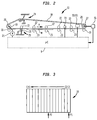
- Figure 1 shows a mail handling machine 1 including a mailing machine 3, a meter 5, and a printhead module 7.
- Mailing machine 3 includes a microcontroller 9, a mailpiece sensor 11, a mailpiece transport mechanism 13, an encoding mechanism 15, and other functional components which for the sake of simplicity have been grouped together and shown at 17.
- the grouped modules may include, for example, a sealing module, a front end feeder, a singulator and a weighing module all of which are in communication with and controlled by microcontroller 9.
- transport mechanism 13 includes a continuous belt 18 driven around a drive pulley 19 and an encoder pulley 20 by a motor 21.
- Belt 18 cooperates with a series of idler pulleys 22 and normal pulleys 23 to move individual mailpieces "M" through the mail handling system 1.
- a tensioning pulley assembly is generally shown at 24 to provide proper belt tension and each normal pulley 23 is biased toward the belt 18 by a biasing structure 25 (only one shown) to accommodate various thickness mailpieces which are being transported by transport mechanism 13.
- Motor 21 is connected by a conventional drive train to a shaft 26 around which drive pulley 19 is fixedly mounted and is controlled by microcontroller 9 to regulate the speed at which the individual mailpieces "M" are transported.
- the encoding mechanism 15 includes a conventional disk and optical detection device such as the respectively known Hewlett-Packard model numbers 5100 and 9100.
- Encoding mechanism 15 is operatively associated with a shaft 27 around which the encoder pulley 20 is fixedly mounted and provides signals to microcontroller 9 which signals are indicative of the velocity of the transported mailpieces "M".
- microcontroller 9 determines the velocity of individual mailpieces "M" change such as, for example, when a light mailpiece is immediately followed by a heavy mailpiece.
- the microcontroller 9 controls motor 21 to compensate for mailpiece velocity variations to maintain as consistent a mailpiece "M" throughput as possible.
- This conventional closed loop motor control feedback system is known in the art and is more fully described in United States Patent 5,740,728.
- postage meter 5 includes conventional accounting circuitry 31 which keeps track of the amount of postage dispensed by postage meter 5 as well as the total amount of postage funds which have been added to postage meter 5 over its life. Additionally, postage meter 5 includes an image ASIC 33 which generates the image data utilized by the printhead module 7 to print the postage indicium image for the particular postage transaction requested. Image ASIC 33, which is also referred to herein as an image generating engine, obtains image data elements from a non-volatile (NVM) memory 35 and outputs this data in a synchronous data stream as set forth in the aforementioned United States Patent Number 5,561,103.
- NVM non-volatile
- the synchronous data stream is not directly transmitted to a printhead module but is first sent to a security ASIC 37 within postage meter 5.
- the security ASIC 37 includes a First In First Out (FIFO) memory device 39, an encryption module 41, a shift register 43 and other control circuitry 44 for controlling operation of security ASIC 37.
- the image data stream of image ASIC 33 is first stored in FIFO 39 and is subsequently sent to encryption module 41, shift register 43 and printhead module 7.
- the encryption module 41 is utilized to encrypt the image data being transmitted between the postage meter 5 and the printhead module 7 to prevent it from being easily compromised.
- bit map image data for the indicium image to be printed on that mailpiece "M” needs to be generated.
- the postage meter 5 receives a message from the microcontroller 9 that a postage indicium of a particular value needs to be printed on that mailpiece "M”.
- the postage meter 5 accounts for the postage in accounting circuitry 31 and begins acquiring the necessary image data elements from the NVM 35 via the image ASIC 33.
- Image ASIC 33 sends the obtained image data in a serial and synchronous manner to FIFO 39 where it is buffered for subsequent use as described in more detail below.
- each clock pulse of a clock (not shown) of image ASIC 33 eight blocks of data are sent with each data block containing 64 bits of data.
- each individual data block is then sent in a parallel manner to encryption module 41 where it is encrypted and subsequently sent to shift register 43.
- the block of data in shift register 43 is then sent to a printhead ASIC 45 where it is decrypted.
- the decrypted data block is then sent to a first printhead buffer 47 until it is latched, upon receipt of a latch signal 48 from printhead ASIC 45, into a second printhead buffer 49.
- printhead module 7 further includes third and fourth printhead buffers 55, 57 which operatively interact with a second printhead 59 having printhead nozzles 61 based on latch signal 62 and fire pulse 63 in the same manner described above in connection with first printhead 51 and its associated buffers 47, 49.
- two printheads 51 and 59 are utilized to print the indicium.
- the printheads 51 and 59 are offset from each other in the direction of arrow "A" of Figure 2 such that printhead 51 prints the bottom half of the image and printhead 59 prints the top half of the indicium image.
- the image generator 33 sequentially and synchronously sends out eight blocks of data with the first two data blocks (128 bits) being for the bottom half of the first column of image data and the second two data blocks being for the top half of the first column of the indicium image.
- the printhead ASIC 45 receives the data stream from shift register 45, it provides the first two data blocks to the buffer 49 via the buffer 47 and the second two data blocks to buffer 57 via buffer 55.
- the next four data blocks are processed in the same manner until the buffers 55 and 47 are filled with image data for the second column of the indicium image to be printed.
- the printheads 51 and 59 are ready to be energized to print.
- the energizing of the printheads 51, 59 is directly related to the number of encoder pulses generated by the encoder mechanism 15. That is, when the lead edge of a mailpiece is sensed by sensor 11, it provides a signal 64 to microcontroller 9 which in turn sends a signal 65 to the printhead ASIC 45 indicative of the presence of the mailpiece "M".
- the ASIC 45 Upon receipt of the signal 65, the ASIC 45 counts a predetermined number of encoder pulses it receives from the encoder mechanism 15 to determine when to send the fire pulse signal 54 to energize the printhead 51 to print the bottom portion of the first column of the image. Then the printhead ASIC 45 sends the fire signal 63, in a time delayed manner relative to the fire signal 54 to account for the distance between the printheads 51 and 59, to energize the printhead 59 to print the top portion of the first column of the indicium image. Thus, when the top portion has been printed, a full column of the indicium image has been printed at the required position on the mailpiece "M" with the top and bottom portions properly aligned.
- the printheads 51 and 59 are energized for each encoder pulse to print the next column of data in the same manner as the first column was printed. Therefore, after the first fire pulses, the first and second latch signals 48 and 62 are respectively sent to the first buffers 47 and 55 to latch the image data stored therein into the corresponding buffers 49 and 57 in preparation of the energizing of the printheads 51 and 59 for printing the second column of image data.
- the buffers 47 and 55 are then ready to receive the next blocks of image data from the shift register 43 in timed sequence with the latching 48, and 62 and firing pulses 54, 63, based on receipt of the encoder pulses by the security ASIC 37.
- the timing of the processing of the blocks of data from the FIFO 39 to the encryption module 41 and the encryption module to the shift register 43 are all timed out based on the encoder pulse so that the exchange of data from the security ASIC 37 to the printheads 51 and 59 is accurately controlled.
- the transmission and use of image data from the FIFO 39 to the printheads 51 and 59 occurs asynchronously.
- the image ASIC 33 generates image data synchronously at eight blocks of data per image ASIC 33 clock pulse.
- the security ASIC 37 buffers the data in the FIFO 39 and turns the image generator 33 on and off as needed to ensure that the image data stored in the FIFO 39 remains within a predetermined range.
- FIFO 39 includes 15 individual registers C1 - C15 which each can store one block (64 bits) of data. Additionally, a pair of pointers P1 and P2 is associated with the registers C1 - C15. That is, pointer P1 identifies the next register C1 - C15 whose block of data is to be sent to encryption module 41, while pointer P2 identifies the next register C1 - C15 that will receive and store the next block of data coming from image ASIC 33. Thus, as a block of data is downloaded to the encryption module 41, the pointer P1 moves to the next sequential register C1 - C15 whose data is next to be downloaded to encryption module 41. Moreover, as FIFO 39 receives a block of image data from image ASIC 33, pointer P2 moves to the next sequential register C1 - C15 which is to receive and store the next block of image data from image ASIC 33.
- Security ASIC 39 is also designed such that it sends an on/off signal 66 to image ASIC 33 which, depending on the on/off signal value (i.e. high or low), turns the image ASIC 33 on or off.
- Security ASIC 37 is designed such that as long as FIFO 39 has greater than or equal to 8 blocks of data (8 of registers C1 - C15) stored therein a low signal is sent to image ASIC 33 turning the image ASIC 33 off such that it stops generating a synchronous image data stream.
- FIFO 39 has less than eight blocks of data stored therein (eight of registers C1 - C15) a high signal is sent to image ASIC 33 which causes image ASIC 33 to begin generating the synchronous image data stream continuing at the point from which it had previously been turned off.
- the determination as to the number of registers C1 - C15 which have data therein is based on the positional difference between pointers P1 and P2.
- the image ASIC 33 will generate at least eight blocks of data for each internal clock pulse.
- the regulated amount of buffered image data within the security ASIC 37 combined with its ability to "switch" the image ASIC 33 on and off ensures that 1) sufficient image data is made available to the printheads 51,59 at the desired asynchronous rate to permit accurate indicia printing and 2) the stored image data is not corrupted by the synchronous generation of image data by the image ASIC 33.
Landscapes
- Physics & Mathematics (AREA)
- Engineering & Computer Science (AREA)
- General Physics & Mathematics (AREA)
- Theoretical Computer Science (AREA)
- Mathematical Physics (AREA)
- Computer Security & Cryptography (AREA)
- Accessory Devices And Overall Control Thereof (AREA)
- Devices For Checking Fares Or Tickets At Control Points (AREA)
- Record Information Processing For Printing (AREA)
Applications Claiming Priority (2)
| Application Number | Priority Date | Filing Date | Title |
|---|---|---|---|
| US09/080,616 US6004048A (en) | 1998-05-18 | 1998-05-18 | Apparatus and method for ensuring good print quality in a mail handling system including a fixed printhead/moving mailpiece subsystem |
| US80616 | 1998-05-18 |
Publications (3)
| Publication Number | Publication Date |
|---|---|
| EP0973133A2 true EP0973133A2 (fr) | 2000-01-19 |
| EP0973133A3 EP0973133A3 (fr) | 2003-10-01 |
| EP0973133B1 EP0973133B1 (fr) | 2006-01-25 |
Family
ID=22158506
Family Applications (1)
| Application Number | Title | Priority Date | Filing Date |
|---|---|---|---|
| EP99108685A Expired - Lifetime EP0973133B1 (fr) | 1998-05-18 | 1999-05-18 | Dispositif et méthode pour assurer une bonne qualité d'impression dans unsystème de traitement de courrier comprenant une tête d'impression fixeet sous-système de courrier mobile |
Country Status (4)
| Country | Link |
|---|---|
| US (1) | US6004048A (fr) |
| EP (1) | EP0973133B1 (fr) |
| CA (1) | CA2272110C (fr) |
| DE (1) | DE69929549T2 (fr) |
Families Citing this family (15)
| Publication number | Priority date | Publication date | Assignee | Title |
|---|---|---|---|---|
| WO2001084435A1 (fr) * | 2000-04-28 | 2001-11-08 | Sheldon Margolis | Dispositif servant a convertir une machine d'alimentation en enveloppes en machine d'affranchissement connectee a internet |
| DE10146842B4 (de) * | 2001-09-24 | 2006-11-09 | Deutsche Post Ag | Verfahren und Vorrichtung zum Bedrucken von Postsendungen |
| US7693800B2 (en) * | 2002-07-09 | 2010-04-06 | Pitney Bowes Inc. | Method and system for metering mixed weight mail pieces at an increased average rate |
| US7516105B2 (en) * | 2003-12-11 | 2009-04-07 | Pitney Bowes Inc. | Method and system for increasing mailing machine throughput by precomputing indicia |
| US20060122951A1 (en) * | 2004-12-03 | 2006-06-08 | Pitney Bowes Incorporated | High speed postage metering device and method utilizing a single print head controller with multiple printing modules |
| US8340476B2 (en) | 2005-03-18 | 2012-12-25 | The Invention Science Fund I, Llc | Electronic acquisition of a hand formed expression and a context of the expression |
| US8823636B2 (en) | 2005-03-18 | 2014-09-02 | The Invention Science Fund I, Llc | Including environmental information in a manual expression |
| US8232979B2 (en) | 2005-05-25 | 2012-07-31 | The Invention Science Fund I, Llc | Performing an action with respect to hand-formed expression |
| US8229252B2 (en) | 2005-03-18 | 2012-07-24 | The Invention Science Fund I, Llc | Electronic association of a user expression and a context of the expression |
| US8290313B2 (en) | 2005-03-18 | 2012-10-16 | The Invention Science Fund I, Llc | Electronic acquisition of a hand formed expression and a context of the expression |
| US7873243B2 (en) | 2005-03-18 | 2011-01-18 | The Invention Science Fund I, Llc | Decoding digital information included in a hand-formed expression |
| US8787706B2 (en) | 2005-03-18 | 2014-07-22 | The Invention Science Fund I, Llc | Acquisition of a user expression and an environment of the expression |
| US8102383B2 (en) | 2005-03-18 | 2012-01-24 | The Invention Science Fund I, Llc | Performing an action with respect to a hand-formed expression |
| US7809215B2 (en) | 2006-10-11 | 2010-10-05 | The Invention Science Fund I, Llc | Contextual information encoded in a formed expression |
| US7672512B2 (en) | 2005-03-18 | 2010-03-02 | Searete Llc | Forms for completion with an electronic writing device |
Citations (4)
| Publication number | Priority date | Publication date | Assignee | Title |
|---|---|---|---|---|
| US5561103A (en) | 1995-09-25 | 1996-10-01 | The Lubrizol Corporation | Functional fluid compositions having improved frictional and anti-oxidation properties |
| US5608636A (en) | 1993-06-21 | 1997-03-04 | Francotyp-Postalia Ag & Co. | Method for controlling the column-by-column printing of a franking image in a postage meter machine |
| US5740728A (en) | 1996-09-23 | 1998-04-21 | Pitney Bowes Inc. | Mailing machine |
| US5815172A (en) | 1996-08-23 | 1998-09-29 | Pitney Bowes, Inc. | Method and structure for controlling the energizing of an ink jet printhead in a value dispensing device such as a postage meter |
Family Cites Families (6)
| Publication number | Priority date | Publication date | Assignee | Title |
|---|---|---|---|---|
| US4706215A (en) * | 1984-08-22 | 1987-11-10 | Pitney Bowes Inc. | Data protection system for electronic postage meters having multiple non-volatile multiple memories |
| US4807141A (en) * | 1985-12-16 | 1989-02-21 | Pitney Bowes Inc. | Postage meter with microprocessor controlled reset inhibiting means |
| CA2003375A1 (fr) * | 1988-12-30 | 1990-06-30 | Nanette Brown | Machine a affranchir electronique a memoire remanente a organisation amelioree |
| CH683652A5 (de) * | 1992-03-10 | 1994-04-15 | Frama Ag | Frankiermaschine. |
| DE69415179T2 (de) * | 1994-09-17 | 1999-07-22 | International Business Machines Corp., Armonk, N.Y. | Verfahren und vorrichtung zur regelung des datenstroms in einem zellbasierten kommunikationsnetz |
| US5651103A (en) * | 1995-11-06 | 1997-07-22 | Pitney Bowes Inc. | Mail handling apparatus and process for printing an image column-by-column in real time |
-
1998
- 1998-05-18 US US09/080,616 patent/US6004048A/en not_active Expired - Fee Related
-
1999
- 1999-05-17 CA CA002272110A patent/CA2272110C/fr not_active Expired - Fee Related
- 1999-05-18 DE DE69929549T patent/DE69929549T2/de not_active Expired - Fee Related
- 1999-05-18 EP EP99108685A patent/EP0973133B1/fr not_active Expired - Lifetime
Patent Citations (4)
| Publication number | Priority date | Publication date | Assignee | Title |
|---|---|---|---|---|
| US5608636A (en) | 1993-06-21 | 1997-03-04 | Francotyp-Postalia Ag & Co. | Method for controlling the column-by-column printing of a franking image in a postage meter machine |
| US5561103A (en) | 1995-09-25 | 1996-10-01 | The Lubrizol Corporation | Functional fluid compositions having improved frictional and anti-oxidation properties |
| US5815172A (en) | 1996-08-23 | 1998-09-29 | Pitney Bowes, Inc. | Method and structure for controlling the energizing of an ink jet printhead in a value dispensing device such as a postage meter |
| US5740728A (en) | 1996-09-23 | 1998-04-21 | Pitney Bowes Inc. | Mailing machine |
Also Published As
| Publication number | Publication date |
|---|---|
| EP0973133B1 (fr) | 2006-01-25 |
| CA2272110A1 (fr) | 1999-11-18 |
| CA2272110C (fr) | 2001-08-07 |
| DE69929549D1 (de) | 2006-04-13 |
| US6004048A (en) | 1999-12-21 |
| DE69929549T2 (de) | 2006-09-28 |
| EP0973133A3 (fr) | 2003-10-01 |
Similar Documents
| Publication | Publication Date | Title |
|---|---|---|
| US6004048A (en) | Apparatus and method for ensuring good print quality in a mail handling system including a fixed printhead/moving mailpiece subsystem | |
| US5956051A (en) | Disabling a mailing machine when a print head is not installed | |
| US5730049A (en) | Method and apparatus for high speed printing in a mailing machine | |
| US6389327B1 (en) | Mail processing system with a franking and addressing machine and method for combined franking and address printing | |
| US20080192073A1 (en) | Apparatus For Converting An Envelope Feeding Machine Into An Internet Connected Postage Machine | |
| US6182566B1 (en) | Printer device and method for printing on a print medium | |
| US7328995B2 (en) | Method and apparatus for embedding information in an image | |
| US6988842B2 (en) | Method and apparatus for continuous high speed digital metering using multiple print heads | |
| CA2241718C (fr) | Machine a affranchir connectable a une interface utilisateur externe | |
| CA2224960C (fr) | Appareil et methode d'impression double face | |
| US6893175B2 (en) | Method and system for high speed digital metering | |
| US6692168B1 (en) | Method and system for secure printing of images | |
| US7059694B2 (en) | Method and system for securing printing process in mailing systems with multiple print heads | |
| US9299196B2 (en) | Method and system for high speed printing using drop-on demand technology that compensates for droplet satellites | |
| US7494201B2 (en) | System and method for reducing printing errors by limiting the firing frequency of a print head | |
| US8510231B2 (en) | Method and system for printing multiple regions across a mail piece | |
| US6505902B1 (en) | Mail piece producing machine having a wide swath envelope printing module | |
| US20060122951A1 (en) | High speed postage metering device and method utilizing a single print head controller with multiple printing modules | |
| EP1392516B1 (fr) | Prevention de la perte de credit pour machines a affranchir et compteurs sur ordinateurs personnels | |
| US7516105B2 (en) | Method and system for increasing mailing machine throughput by precomputing indicia | |
| EP1521218B1 (fr) | Procédé et système pour l'affranchissement numérique rapide | |
| CA2425154A1 (fr) | Systeme de mise hors fonction d'une machine de traitement du courrier sans tete d'impression |
Legal Events
| Date | Code | Title | Description |
|---|---|---|---|
| PUAI | Public reference made under article 153(3) epc to a published international application that has entered the european phase |
Free format text: ORIGINAL CODE: 0009012 |
|
| AK | Designated contracting states |
Kind code of ref document: A2 Designated state(s): AT BE CH CY DE DK ES FI FR GB GR IE IT LI LU MC NL PT SE |
|
| AX | Request for extension of the european patent |
Free format text: AL;LT;LV;MK;RO;SI |
|
| PUAL | Search report despatched |
Free format text: ORIGINAL CODE: 0009013 |
|
| AK | Designated contracting states |
Kind code of ref document: A3 Designated state(s): AT BE CH CY DE DK ES FI FR GB GR IE IT LI LU MC NL PT SE |
|
| AX | Request for extension of the european patent |
Extension state: AL LT LV MK RO SI |
|
| RIC1 | Information provided on ipc code assigned before grant |
Ipc: 7H 04L 12/56 B Ipc: 7G 07B 17/00 A |
|
| 17P | Request for examination filed |
Effective date: 20040331 |
|
| AKX | Designation fees paid |
Designated state(s): DE FR GB |
|
| 17Q | First examination report despatched |
Effective date: 20040514 |
|
| GRAP | Despatch of communication of intention to grant a patent |
Free format text: ORIGINAL CODE: EPIDOSNIGR1 |
|
| GRAS | Grant fee paid |
Free format text: ORIGINAL CODE: EPIDOSNIGR3 |
|
| GRAA | (expected) grant |
Free format text: ORIGINAL CODE: 0009210 |
|
| AK | Designated contracting states |
Kind code of ref document: B1 Designated state(s): DE FR GB |
|
| REG | Reference to a national code |
Ref country code: GB Ref legal event code: FG4D |
|
| REF | Corresponds to: |
Ref document number: 69929549 Country of ref document: DE Date of ref document: 20060413 Kind code of ref document: P |
|
| ET | Fr: translation filed | ||
| PLBE | No opposition filed within time limit |
Free format text: ORIGINAL CODE: 0009261 |
|
| STAA | Information on the status of an ep patent application or granted ep patent |
Free format text: STATUS: NO OPPOSITION FILED WITHIN TIME LIMIT |
|
| 26N | No opposition filed |
Effective date: 20061026 |
|
| PGFP | Annual fee paid to national office [announced via postgrant information from national office to epo] |
Ref country code: DE Payment date: 20070702 Year of fee payment: 9 |
|
| PGFP | Annual fee paid to national office [announced via postgrant information from national office to epo] |
Ref country code: GB Payment date: 20070525 Year of fee payment: 9 |
|
| PGFP | Annual fee paid to national office [announced via postgrant information from national office to epo] |
Ref country code: FR Payment date: 20070517 Year of fee payment: 9 |
|
| GBPC | Gb: european patent ceased through non-payment of renewal fee |
Effective date: 20080518 |
|
| REG | Reference to a national code |
Ref country code: FR Ref legal event code: ST Effective date: 20090119 |
|
| PG25 | Lapsed in a contracting state [announced via postgrant information from national office to epo] |
Ref country code: FR Free format text: LAPSE BECAUSE OF NON-PAYMENT OF DUE FEES Effective date: 20080602 Ref country code: DE Free format text: LAPSE BECAUSE OF NON-PAYMENT OF DUE FEES Effective date: 20081202 |
|
| PG25 | Lapsed in a contracting state [announced via postgrant information from national office to epo] |
Ref country code: GB Free format text: LAPSE BECAUSE OF NON-PAYMENT OF DUE FEES Effective date: 20080518 |