EP0973151B1 - Arrangement de contrôle du bruit - Google Patents
Arrangement de contrôle du bruit Download PDFInfo
- Publication number
- EP0973151B1 EP0973151B1 EP99113651A EP99113651A EP0973151B1 EP 0973151 B1 EP0973151 B1 EP 0973151B1 EP 99113651 A EP99113651 A EP 99113651A EP 99113651 A EP99113651 A EP 99113651A EP 0973151 B1 EP0973151 B1 EP 0973151B1
- Authority
- EP
- European Patent Office
- Prior art keywords
- output
- coefficient
- digital filter
- noise
- adder
- Prior art date
- Legal status (The legal status is an assumption and is not a legal conclusion. Google has not performed a legal analysis and makes no representation as to the accuracy of the status listed.)
- Expired - Lifetime
Links
Images


Classifications
-
- G—PHYSICS
- G10—MUSICAL INSTRUMENTS; ACOUSTICS
- G10K—SOUND-PRODUCING DEVICES; METHODS OR DEVICES FOR PROTECTING AGAINST, OR FOR DAMPING, NOISE OR OTHER ACOUSTIC WAVES IN GENERAL; ACOUSTICS NOT OTHERWISE PROVIDED FOR
- G10K11/00—Methods or devices for transmitting, conducting or directing sound in general; Methods or devices for protecting against, or for damping, noise or other acoustic waves in general
- G10K11/16—Methods or devices for protecting against, or for damping, noise or other acoustic waves in general
- G10K11/175—Methods or devices for protecting against, or for damping, noise or other acoustic waves in general using interference effects; Masking sound
- G10K11/178—Methods or devices for protecting against, or for damping, noise or other acoustic waves in general using interference effects; Masking sound by electro-acoustically regenerating the original acoustic waves in anti-phase
- G10K11/1781—Methods or devices for protecting against, or for damping, noise or other acoustic waves in general using interference effects; Masking sound by electro-acoustically regenerating the original acoustic waves in anti-phase characterised by the analysis of input or output signals, e.g. frequency range, modes, transfer functions
- G10K11/17821—Methods or devices for protecting against, or for damping, noise or other acoustic waves in general using interference effects; Masking sound by electro-acoustically regenerating the original acoustic waves in anti-phase characterised by the analysis of input or output signals, e.g. frequency range, modes, transfer functions characterised by the analysis of the input signals only
- G10K11/17825—Error signals
-
- G—PHYSICS
- G10—MUSICAL INSTRUMENTS; ACOUSTICS
- G10K—SOUND-PRODUCING DEVICES; METHODS OR DEVICES FOR PROTECTING AGAINST, OR FOR DAMPING, NOISE OR OTHER ACOUSTIC WAVES IN GENERAL; ACOUSTICS NOT OTHERWISE PROVIDED FOR
- G10K11/00—Methods or devices for transmitting, conducting or directing sound in general; Methods or devices for protecting against, or for damping, noise or other acoustic waves in general
- G10K11/16—Methods or devices for protecting against, or for damping, noise or other acoustic waves in general
- G10K11/175—Methods or devices for protecting against, or for damping, noise or other acoustic waves in general using interference effects; Masking sound
- G10K11/178—Methods or devices for protecting against, or for damping, noise or other acoustic waves in general using interference effects; Masking sound by electro-acoustically regenerating the original acoustic waves in anti-phase
- G10K11/1783—Methods or devices for protecting against, or for damping, noise or other acoustic waves in general using interference effects; Masking sound by electro-acoustically regenerating the original acoustic waves in anti-phase handling or detecting of non-standard events or conditions, e.g. changing operating modes under specific operating conditions
- G10K11/17833—Methods or devices for protecting against, or for damping, noise or other acoustic waves in general using interference effects; Masking sound by electro-acoustically regenerating the original acoustic waves in anti-phase handling or detecting of non-standard events or conditions, e.g. changing operating modes under specific operating conditions by using a self-diagnostic function or a malfunction prevention function, e.g. detecting abnormal output levels
-
- G—PHYSICS
- G10—MUSICAL INSTRUMENTS; ACOUSTICS
- G10K—SOUND-PRODUCING DEVICES; METHODS OR DEVICES FOR PROTECTING AGAINST, OR FOR DAMPING, NOISE OR OTHER ACOUSTIC WAVES IN GENERAL; ACOUSTICS NOT OTHERWISE PROVIDED FOR
- G10K11/00—Methods or devices for transmitting, conducting or directing sound in general; Methods or devices for protecting against, or for damping, noise or other acoustic waves in general
- G10K11/16—Methods or devices for protecting against, or for damping, noise or other acoustic waves in general
- G10K11/175—Methods or devices for protecting against, or for damping, noise or other acoustic waves in general using interference effects; Masking sound
- G10K11/178—Methods or devices for protecting against, or for damping, noise or other acoustic waves in general using interference effects; Masking sound by electro-acoustically regenerating the original acoustic waves in anti-phase
- G10K11/1785—Methods, e.g. algorithms; Devices
- G10K11/17853—Methods, e.g. algorithms; Devices of the filter
- G10K11/17854—Methods, e.g. algorithms; Devices of the filter the filter being an adaptive filter
-
- G—PHYSICS
- G10—MUSICAL INSTRUMENTS; ACOUSTICS
- G10K—SOUND-PRODUCING DEVICES; METHODS OR DEVICES FOR PROTECTING AGAINST, OR FOR DAMPING, NOISE OR OTHER ACOUSTIC WAVES IN GENERAL; ACOUSTICS NOT OTHERWISE PROVIDED FOR
- G10K11/00—Methods or devices for transmitting, conducting or directing sound in general; Methods or devices for protecting against, or for damping, noise or other acoustic waves in general
- G10K11/16—Methods or devices for protecting against, or for damping, noise or other acoustic waves in general
- G10K11/175—Methods or devices for protecting against, or for damping, noise or other acoustic waves in general using interference effects; Masking sound
- G10K11/178—Methods or devices for protecting against, or for damping, noise or other acoustic waves in general using interference effects; Masking sound by electro-acoustically regenerating the original acoustic waves in anti-phase
- G10K11/1787—General system configurations
- G10K11/17879—General system configurations using both a reference signal and an error signal
- G10K11/17881—General system configurations using both a reference signal and an error signal the reference signal being an acoustic signal, e.g. recorded with a microphone
-
- G—PHYSICS
- G10—MUSICAL INSTRUMENTS; ACOUSTICS
- G10K—SOUND-PRODUCING DEVICES; METHODS OR DEVICES FOR PROTECTING AGAINST, OR FOR DAMPING, NOISE OR OTHER ACOUSTIC WAVES IN GENERAL; ACOUSTICS NOT OTHERWISE PROVIDED FOR
- G10K2210/00—Details of active noise control [ANC] covered by G10K11/178 but not provided for in any of its subgroups
- G10K2210/30—Means
- G10K2210/301—Computational
- G10K2210/3012—Algorithms
-
- G—PHYSICS
- G10—MUSICAL INSTRUMENTS; ACOUSTICS
- G10K—SOUND-PRODUCING DEVICES; METHODS OR DEVICES FOR PROTECTING AGAINST, OR FOR DAMPING, NOISE OR OTHER ACOUSTIC WAVES IN GENERAL; ACOUSTICS NOT OTHERWISE PROVIDED FOR
- G10K2210/00—Details of active noise control [ANC] covered by G10K11/178 but not provided for in any of its subgroups
- G10K2210/30—Means
- G10K2210/301—Computational
- G10K2210/3027—Feedforward
-
- G—PHYSICS
- G10—MUSICAL INSTRUMENTS; ACOUSTICS
- G10K—SOUND-PRODUCING DEVICES; METHODS OR DEVICES FOR PROTECTING AGAINST, OR FOR DAMPING, NOISE OR OTHER ACOUSTIC WAVES IN GENERAL; ACOUSTICS NOT OTHERWISE PROVIDED FOR
- G10K2210/00—Details of active noise control [ANC] covered by G10K11/178 but not provided for in any of its subgroups
- G10K2210/30—Means
- G10K2210/301—Computational
- G10K2210/3039—Nonlinear, e.g. clipping, numerical truncation, thresholding or variable input and output gain
Definitions
- the present invention relates to a noise control system based on active noise control, for use in a noisy environment.
- This type of a noise control system in the conventional art employs an adaptive filter for calculating a noise control signal, and may further employ an auxiliary adaptive filter for preventing an increase in the gain of the adaptive filter, as disclosed in, for example, Japanese Laid-Open Publication No. 5-67948 .
- FIG 22 is a block diagram illustrating a structure of such a conventional noise control system.
- the noise control system includes a control speaker 1 , an error detection microphone 2 which functions as an error detector, a noise detection microphone 3 which functions as a noise detector, adaptive filters 4 and 15 , a digital filter 5 which approximates the propagation characteristic between the control speaker 1 and the error detection microphone 2 , coefficient update calculators 6 and 9 , and a digital filter 7 having a frequency band limiting characteristic.
- noise generated from a noise source is detected by the noise detector 3 , and a noise source signal is generated based on the detection result.
- the generated noise source signal is processed by the adaptive filter 4 , so as to output a control signal.
- a control sound is generated from the control speaker 1 based on the control signal so that the control sound interferes with the noise from the noise source, thereby reducing the noise.
- the state of interference between the control sound output from the control speaker 1 and the noise is measured by the error detector (microphone) 2 .
- the output of the error detector (microphone) 2 should ideally be zero as a result of the noise control. Therefore, the coefficient update calculator 6 performs a calculation such that the output signal of the error detector (microphone) 2 is reduced, and controls the coefficient of the adaptive filter 4 based on the calculation result.
- the coefficient update calculator 9 performs a calculation such that the output of the adaptive filter 15 is reduced, and controls the coefficient of the adaptive filter 15 based on the calculation result.
- a band limiting signal produced by the digital filter 7 is input to the adaptive filter 15, and the coefficient of the adaptive filter 15 converges into a value which suppresses signals in the band.
- the coefficients of the adaptive filters 4 and 15 can be shared by each other so as to combine the effects of the two coefficient update calculators 6 and 9 together, and the update operation of the coefficient of the adaptive filter 4 is suppressed in a band which is set in the digital filter 7 .
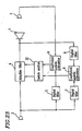
- FIG 23 is a block diagram illustrating a structure of another conventional noise control system as disclosed in Japanese Laid-Open Publication No. 7-271383 .
- the noise control system includes a control speaker 1 , an error detection microphone 2 which functions as an error detector, a noise detection microphone 3 which functions as a noise detector, an adaptive filter 4 , a digital filter 5 which approximates the propagation characteristic between the control speaker 1 and the error detection microphone 2 , coefficient update calculators 6 and 9 , digital filters 7 and 8 each having a frequency band limiting characteristic, and a switch section 32 .
- noise generated from a noise source is detected by the noise detector 3 , and a noise source signal is generated based on the detection result.
- the generated noise source signal is processed by the adaptive filter 4 , so as to output a control signal.
- a control sound is generated from the control speaker 1 based on the control signal so that the control sound interferes with the noise from the noise source, thereby reducing the noise.
- the state of interference between the control sound output from the control speaker 1 and the noise is measured by the error detector (microphone) 2 .
- the output of the error detector (microphone) 2 should ideally be zero as a result of the noise control. Therefore, the coefficient update calculator 6 performs a calculation such that the output signal of the error detector (microphone) 2 is reduced.
- a band limiting signal produced by the digital filter 7 and another band limiting signal produced by the digital filter 8 are input to the coefficient update calculator 9 , and the coefficient update calculator 9 performs a coefficient update calculation such that the adaptive filter 4 suppresses the output of the signal in the band.
- the switch section 32 switches between the outputs of the coefficient update calculators 6 and 9 , so as to control the update operation of the band limitation by the digital filters 7 and 8 .
- the conventional noise control system as illustrated in Figure 22 requires the auxiliary adaptive filter 15 for controlling the update operation of the coefficient of the adaptive filter 4 , thereby increasing the amount of calculation to be performed.
- the other conventional noise control system as illustrated in Figure 23 requires two coefficient update calculators 6 and 9 , thereby increasing the amount of calculation to be performed. Moreover, since the switching between the outputs of the coefficient update calculators 6 and 9 is done by the switch section 32 , coefficient update operations of the adaptive filter by the coefficient update calculators 6 and 9 cannot be arbitrarily weighed.
- US-5,278,780 discloses a system using plurality of adaptive digital filters.
- a main adaptive digital filter and a sub adaptive digital filter are provided, and these two adaptive digital filters share a filter coefficient to be controlled.
- the shared coefficient is updated so that the difference between the output and a desired response is minimized and on the side of the subadapted digital filter, the above-stated shared filter coefficient is updated so that the output is minimized.
- a prescribed limitation is given to the frequency characteristic of a filter coefficient to be adapted, by treating the input of the sub adaptive digital filter as a signal weighted on the frequency or a noise having its band limited with respect to the input signal or the output signal of the main adaptive digital filter, and coefficient updating control is conducted so that the coefficient will not go beyond the limitation.
- EP 0 616 314 A discloses an active noise attenuating device of the adaptive control type.
- the active noise attenuating device includes a first microphone located in a propagation path of noise, a loud speaker located downstream from the first microphone, a second microphone located downstream from the loud speaker for receiving sound, and an operational unit for executing an operation on the basis of a detection signal from the first microphone to generate a control signal supplied to the loud speaker so that a sound interfering with the noise is produced.
- An operational factor of the operational unit is controlled by an adaptive controller on the basis of the detection signal from the second microphone so that an amount of noise attenuated by the sound produced from the loud speaker is rendered maximum.
- a transfer characteristic of a transfer path between the loud speaker and the second microphone is identified on the basis of the detection signals generated by the second microphone when a sound represented by a periodical identifying signal is produced in a plurality of periods.
- An operational factor of the adaptive controller is adjusted by an adaptive control identifying unit on the basis of the identified transfer characteristic.
- the invention is defined by the subject-matter of the independent claims.
- the dependent claims are directed to advantageous embodiments.
- An advantageous noise control system includes: a control sound generator for generating a control sound; an error detector for detecting an error signal between the control sound and noise; a noise detector for detecting a noise source signal; an adaptive filter for outputting a control signal; and a coefficient updator for updating a coefficient of the adaptive filter, the coefficient updator comprising at least a first digital filter, a first coefficient update calculator, a second digital filter, a phase inverter, a third digital filter, and a second coefficient update calculator.
- the coefficient updator has a function of suppressing an increase in a coefficient gain of the adaptive filter in a predetermined frequency band.
- the coefficient updator is such that: the first digital filter receives, as an input thereto, an output of the noise detector; the first coefficient update calculator receives, as inputs thereto, an output of the first digital filter and an output of the error detector; the phase inverter inverts the output of the noise detector; the second digital filter receives, as an input thereto, an output of the phase inverter; the third digital filter receives, as an input thereto, the output of the error detector; the second coefficient update calculator receives, as inputs thereto, outputs of the second and third digital filters; the first digital filter approximates a propagation characteristic between the control sound generator and the error detector; the second and third digital filters have a common passband frequency characteristic; the first coefficient update calculator performs a calculation such that the output of the error detector is reduced, and updates the coefficient of the adaptive filter based on the calculation result; and the second coefficient update calculator performs a calculation such that the output of the third digital filter is reduced, and updates the coefficient of the adaptive filter based on the output of the coefficient update calculator
- the coefficient updator is such that: the first digital filter receives, as an input thereto, an output of the noise detector; the first coefficient update calculator receives, as inputs thereto, an output of the first digital filter and an output of the error detector; the second digital filter receives, as an input thereto, an output of the noise detector; the third digital filter receives, as an input thereto, the output of the error detector; the second coefficient update calculator receives, as inputs thereto, outputs of the second and third digital filters; the phase inverter inverts an output of the second coefficient update calculator; the first digital filter approximates a propagation characteristic between the control sound generator and the error detector; the second and third digital filters have a common passband frequency characteristic; the first coefficient update calculator performs a calculation such that the output of the error detector is reduced, and updates the coefficient of the adaptive filter based on the calculation result; and the second coefficient update calculator performs a calculation such that the output of the third digital filter is reduced, inverts and outputs the calculation result, and updates the coefficient of the adaptive filter
- the coefficient updator further includes: a first selection controller for thinning out the outputs of the first coefficient update calculator; a second selection controller for thinning out the outputs of the second coefficient update calculator; and a selection control calculator for receiving an output signal of the third digital filter to control the first and second selection controllers;
- the first digital filter receives, as an input thereto, an output of the noise detector;
- the first coefficient update calculator receives, as inputs thereto, an output of the first digital filter and an output of the error detector;
- the phase inverter inverts an output of the adaptive filter;
- the third digital filter receives, as an input thereto, an output of the phase inverter;
- the second coefficient update calculator receives, as inputs thereto, outputs of the second and third digital filters;
- the first digital filter approximates a propagation characteristic between the control sound generator and the error detector;
- the second and third digital filters have a common passband frequency characteristic;
- the first coefficient update calculator performs a calculation such that the output of the error detector
- the coefficient updator further includes: a first selection controller for switching between selecting an output of the first coefficient update calculator and selecting nothing; a second selection controller for switching between selecting an output of the second coefficient update calculator and selecting nothing; and a selection control calculator for receiving an output signal of the third digital filter to control the first and second selection controllers;
- the first digital filter receives, as an input thereto, an output of the noise detector;
- the first coefficient update calculator receives, as inputs thereto, an output of the first digital filter and an output of the error detector;
- the phase inverter inverts an output of the adaptive filter;
- the third digital filter receives, as an input thereto, an output of the phase inverter;
- the second coefficient update calculator receives, as inputs thereto, outputs of the second and third digital filters;
- the first digital filter approximates a propagation characteristic between the control sound generator and the error detector;
- the second and third digital filters have a common passband frequency characteristic;
- the first coefficient update calculator performs a calculation such that the output of the
- the coefficient updator further includes: a signal level converter for receiving an output signal of the third digital filter to convert a level of the signal; and a multiplier for multiplying an output of the signal level converter by an output of the second coefficient update calculator so as to update the coefficient of the adaptive filter;
- the first digital filter receives, as an input thereto, an output of the noise detector;
- the first coefficient update calculator receives, as inputs thereto, an output of the first digital filter and an output of the error detector;
- the second digital filter receives, as an input thereto, the output of the noise detector;
- the phase inverter inverts an output of the adaptive filter;
- the third digital filter receives, as an input thereto, an output of the phase inverter;
- the second coefficient update calculator receives, as inputs thereto, outputs of the second and third digital filters;
- the first digital filter approximates a propagation characteristic between the control sound generator and the error detector;
- the second and third digital filters have a common passband frequency characteristic;
- the predetermined frequency band may exist in a low frequency region.
- the predetermined frequency band may be a frequency region where the frequency is less than or equal to a lower limit reproducible frequency of the control sound generator.
- Another advantageous noise control system includes: a control sound generator for generating a control sound; an error detector for detecting an error signal between the control sound and noise; a noise detector for detecting a noise source signal; an adaptive filter for outputting a control signal; and a coefficient updator for updating a coefficient of the adaptive filter, the coefficient updator comprising at least a first digital filter, a second digital filter, a third digital filter, a coefficient update calculator, a phase inverter, a first adder, and a second adder.
- the coefficient updator has a function of suppressing an increase in a coefficient gain of the adaptive filter in a predetermined frequency band.
- the coefficient updator is such that: the first digital filter receives, as an input thereto, an output of the noise detector; the second digital filter receives, as an input thereto, the output of the noise detector; the first adder receives, as inputs thereto, an output of the first digital filter and an output of the second digital filter; the second adder receives, as inputs thereto, an output of the error detector and an output of the third digital filter; the coefficient update calculator receives, as inputs thereto, an output of the first adder and an output of the second adder; the phase inverter inverts an output of the adaptive filter; the third digital filter receives, as an input thereto, the output of the phase inverter; the first digital filter approximates a propagation characteristic between the control sound generator and the error detector; the second and third digital filters have a common passband frequency characteristic; and the coefficient update calculator performs a calculation such that the output of the second adder is reduced, and updates the coefficient of the adaptive filter based on the calculation result.
- the coefficient updator is such that: the first digital filter receives, as an input thereto, an output of the noise detector; the phase inverter inverts the output of the noise detector: the second digital filter receives, as an input thereto, the output of the phase inverter; the first adder receives, as inputs thereto, an output of the first digital filter and an output of the second digital filter; the second adder receives, as inputs thereto, an output of the error detector and an output of the third digital filter; the coefficient update calculator receives, as inputs thereto, an output of the first adder and an output of the second adder; the third digital filter receives, as an input thereto, an output of the adaptive filter; the first digital filter approximates a propagation characteristic between the control sound generator and the error detector; the second and third digital filters have a common passband frequency characteristic; and the coefficient update calculator performs a calculation such that the output of the second adder is reduced, and updates the coefficient of the adaptive filter based on the calculation result.
- the coefficient updator further includes: a first coefficient controller for multiplying an output of the second digital filter by a first coefficient factor; and a second coefficient controller for multiplying an output of the third digital filter by a second coefficient factor;
- the first digital filter receives, as an input thereto, an output of the noise detector;
- the second digital filter receives, as an input thereto, the output of the noise detector;
- the first adder receives, as inputs thereto, an output of the first digital filter and an output of the first coefficient controller;
- the second adder receives, as inputs thereto, an output of the error detector and an output of the second coefficient controller;
- the coefficient update calculator receives, as inputs thereto, an output of the first adder and an output of the second adder;
- the phase inverter inverts an output of the adaptive filter;
- the third digital filter receives, as an input thereto, the output of the phase inverter; each of the first coefficient factor and the second coefficient factor is set to be equal to or more than 1; the first
- the first coefficient controller may be set so that in a passband of the second digital filter, the output of the first coefficient controller is larger than an output signal of the first digital filter.
- the second coefficient controller may be set so that in a passband of the third digital filter, the output of the second coefficient controller is larger than an output signal of the error detector.
- the coefficient updator further includes: a first coefficient controller for multiplying an output of the first digital filter by a first coefficient factor; and a second coefficient controller for multiplying an output of the error detector by a second coefficient factor;
- the first digital filter receives, as an input thereto, an output of the noise detector;
- the second digital filter receives, as an input thereto, the output of the noise detector;
- the first adder receives, as inputs thereto, an output of the first coefficient controller and an output of the second digital filter;
- the second adder receives, as inputs thereto, an output of the second coefficient controller and an output of the third digital filter;
- the coefficient update calculator receives, as inputs thereto, an output of the first adder and an output of the second adder;
- the phase inverter inverts an output of the adaptive filter;
- the third digital filter receives, as an input thereto, the output of the phase inverter; each of the first coefficient factor and the second coefficient factor is set to be less than or equal to 1; the first
- the first coefficient controller may be set so that in a passband of the second digital filter, the output of the first coefficient controller is smaller than an output signal of the first digital filter.
- the second coefficient controller may be set so that in a passband of the third digital filter, the output of the second coefficient controller is smaller than an output signal of the error detector.
- the predetermined frequency band may exist in a low frequency region.
- the predetermined frequency band may be a frequency region where the frequency is less than or equal to a lower limit reproducible frequency of the control sound generator.
- the predetermined frequency band may exist in a frequency region where there is a correlation between an output signal of the noise detector and an output signal of the error detector.
- the noise detection signal and the adaptive filter output signal are processed by the band limiting digital filters, which have the same characteristic, so as to produce a coefficient update signal in the negative direction from both of the output signals, thereby controlling the adaptive filter used in a noise control calculation.
- the present invention prevents an undesired increase in the coefficient gain of the adaptive filter in the band of the above-described digital filter, while realizing a coefficient control of the adaptive filter used in a noise control calculation without having to use additional hardware such as an adaptive filter or an additional calculation process, thereby realizing a stable noise processing operation.
- the update frequency, at which the negative coefficient update for the adaptive filter is performed is controlled in view of the non-linear characteristic of the noise propagation system or the control sound generator, whereby it is possible to realize a noise control with no band limitation when the noise signal is small.
- a noise control system capable of a stable noise processing operation by controlling the coefficient of an adaptive filter used in noise control calculations without having to provide additional hardware such as an adaptive filter or an additional calculation process.
- a low frequency band of the control signal is limited so that the adaptive filter does not generate an excessive control signal for noise having a frequency which is too low for the low band reproducibility of the control speaker.
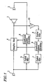
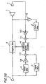
- FIG. 1 is a block diagram illustrating a structure of the noise control system of this embodiment.
- the noise control system includes a control speaker 1 , an error detection microphone 2 which functions as an error detector, a noise detection microphone 3 which functions as a noise detector, an adaptive filter 4 , a digital filter 5 which approximates the propagation characteristic between the control speaker 1 and the error detection microphone 2 , coefficient update calculators 6 and 9 , digital filters 7 and 8 each having a frequency band limiting characteristic (band limiting filters), and a phase inverter 10 for inverting the output of the adaptive filter 4 .
- noise generated from a noise source is detected by a noise detector 3 , and a noise source signal is generated based on the detection result.
- the generated noise source signal is processed by the adaptive filter 4 , so as to output a control signal.
- a control sound is generated from the control speaker 1 based on the control signal so that the control sound interferes with the noise from the noise source, thereby reducing the noise.
- the state of interference between the control sound output from the control speaker 1 and the noise is measured by the error detector (microphone) 2 .
- the output of the error detector (microphone) 2 should ideally be zero as a result of the noise control. Therefore, the coefficient update calculator 6 performs a coefficient update calculation as shown in Expression (1) later based on a filtered X-LMS method (see Widrow and Stearns, "Adaptive Signal Processing", 1985 ), or the like, so as to adjust the characteristic of the adaptive filter 4 , such that the output signal of the error detector (microphone) 2 is reduced. This changes the control sound actually generated from the control speaker 1 , thereby further reducing the noise.
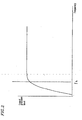
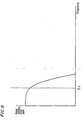
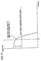
- the frequency characteristic of the control speaker 1 is such that the sound pressure of an output thereof is reduced in a frequency region where the frequency is less than or equal to the lower limit reproducible frequency f L , as shown in Figure 2 .
- the coefficient gain of the adaptive filter 4 is required to sufficiently reduce (or cancel) the noise in the low frequency region while compensating for the characteristic of the control speaker 1 , thereby converging into the characteristic as illustrated in Figure 3 , where the gain has an increase in the low frequency region (a region where the frequency is less than or equal to the lower limit reproducible frequency f L of the control speaker 1 ). In such a case, a large low frequency signal is input to the control speaker 1 .
- the distortion may act as an error signal, thereby causing an adverse effect such as making the operation of the adaptive filter 4 unstable.
- the digital filters 7 and 8 are set to have a band limiting characteristic with a passband characteristic as illustrated in Figure 8 in the low frequency region where the output of the control speaker 1 is reduced (e.g., the frequency region where the frequency is less than or equal to the lower limit reproducible frequency f L of the control speaker 1 ).
- the output signal of the adaptive filter 4 is inverted by the phase inverter 10 and processed by the digital filter 8 so as to obtain an error signal, while processing the output signal of the noise detector 3 by the digital filter 7 and inputting the processed signal as a reference signal to the coefficient update calculator 9 .
- the coefficient update calculator 9 performs a calculation according to Expression (2) to be described later, using an algorithm similar to that of the coefficient update calculator 6 .
- the coefficient of the adaptive filter 4 is updated by both of the coefficient update calculators 6 and 9 using an update calculation according to Expression (3) to be described later.
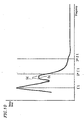
- the coefficient update calculator 9 operates so as to reduce the output signal of the digital filter 7 , whereby the increase in the coefficient gain of the adaptive filter 4 is suppressed in the low frequency region as illustrated by the solid line (b) in Figure 9 .
- a broken line (a) in Figure 9 is a coefficient gain of the adaptive filter 4 which is obtained by using only the coefficient update calculator 6 , illustrated in Figure 3 for updating the coefficient of the adaptive filter 4 .
- a broken line (a) in Figure 10 corresponds to the broken line (a) in Figures 4 and 7 .
- ⁇ W j denotes an output signal vector of the coefficient update calculator 6, ⁇ U j an output signal vector of the coefficient update calculator 9 , W j a coefficient vector of the adaptive filter 4 , R j an output vector of the digital filter 5 , S j an output signal vector of the digital filter 7 , e j an output signal of the error detector, and v j an output signal of the digital filter 8 , all at time j.
- n denotes the order of the adaptive filter 4, and ⁇ and ⁇ are size parameters for a coefficient update step.
- the phase inverter 10 is connected between the adaptive filter 4 and the digital filter 8 .
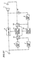
- Functions and effects similar to those described above are also obtained by the structure as illustrated in Figure 11 , where the phase inverter 10 is connected between the noise detector 3 and the digital filter 7 .
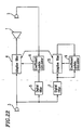
- functions and effects similar to those described above are also obtained by the structure as illustrated in Figure 12 , where the phase inverter 10 is connected to the output of the coefficient update calculator 9 , or by another structure where the phase inverter 10 is connected to the output of the digital filter 8 or the digital filter 7 .
- Elements in the block diagrams of Figures 11 and 12 corresponding to those shown in Figure 1 have like reference numerals, and will not be further described here.
- Figure 13 is a block diagram illustrating a structure of the noise control system of this embodiment. Elements in the block diagram of Figure 13 corresponding to those illustrated in Embodiment 1 with reference to, e.g., Figure 1 have like reference numerals, and will not be further described below.
- the update frequency at which the coefficient update calculation is performed by the coefficient update calculator 6 is increased while the low frequency component of the output of the adaptive filter 4 is small and the control speaker 1 is operating in the linear region.
- the update frequency at which the coefficient update calculation is performed by the coefficient update calculator 9 is increased, when the low frequency component of the output of the adaptive filter 4 increases and the control speaker 1 enters the non-linear region, so as to perform a coefficient update calculation which suppresses the filter gain in the low frequency region. In this way, it is possible not only to sufficiently reduce the noise even in the low frequency region when the noise level is low, but also to perform a stable noise control even when the noise level in the low frequency region is high.
- the illustrated noise control system includes a selector 12 for thinning out the outputs of the coefficient update calculator 6 , another selector 22 for thinning out the outputs of the coefficient update calculator 9 , and a selection control calculator 11 for controlling the operations of the selectors 12 and 22 .
- the other elements and the functions thereof are similar to those described above in Embodiment 1 .
- the selectors 12 and 22 when in the closed position, transfer the outputs of the coefficient update calculators 6 and 9 , respectively, to the adaptive filter 4 , while selecting no signal (or transferring no signal to the adaptive filter 4 ) when in the open position.
- each of the selectors 12 and 22 at a predetermined timing (frequency)
- the selector 12 is closed once for 4 sampling operations to control the adaptive filter by the output of the coefficient update calculator 6 ; and the selector 22 is closed once for 16 sampling operations to control the adaptive filter by the output of the coefficient update calculator 9 .
- the noise control operation is performed by setting the thinning-out frequency of the selector 22 to be lower than that of the selector 12 .
- a low frequency component of the output signal of the adaptive filter 4 is obtained from the digital filter 8 as an output signal thereof.
- the control speaker 1 has a non-linear characteristic in the vicinity of such a low frequency
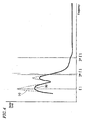
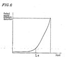
- the output sound pressure is saturated (see Figure 5 ) while the distortion increases considerably (see Figure 6 ), as illustrated in the input-output sound pressure characteristic of Figure 5 and the input-output sound pressure distortion characteristic of Figure 6 .
- noise corresponding to the broken line (a) in Figure 4
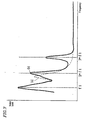
- the conventional adaptive filter 4 whose spectrum at the error detector (microphone) 2 includes signals in the vicinity of the low frequency f1, as illustrated by the broken line (a) in Figure 7
- a sufficient sound elimination cannot be realized because the control sound is saturated at the frequency f1. It may rather lead to generation of a higher harmonic wave distortion at a frequency twice or three times the frequency f1, as illustrated by a solid line (b) in Figure 7 , thereby creating new noise.
- the distortion may act as an error signal, thereby causing an adverse effect such as making the operation of the adaptive filter 4 unstable.
- the output level of a low frequency component of the output from the digital filter 8 is detected by the selection control calculator 11 and, if the output level exceeds Ls, the thinning-out frequencies of the selectors 12 and 22 are controlled so that the thinning-out frequency of the selector 22 is larger than that of the selector 12 .
- the selector 12 is closed once for 16 sampling operations so as to use the output of the coefficient update calculator 6 for updating the coefficient of the adaptive filter 4 only at this timing, thus controlling the adaptive filter 4 while thinning out the outputs of the coefficient update calculator 6 .
- the selector 22 is closed once for 4 sampling operations so as to use the output of the coefficient update calculator 9 for updating the coefficient of the adaptive filter 4 only at this timing, thus controlling the adaptive filter 4 while thinning out the outputs of the coefficient update calculator 9 .
- the coefficient of the adaptive filter 4 is updated based on an output of the coefficient update calculator 9 more often than based on an output of the coefficient update calculator 6 .
- the control speaker 1 operates in the linear region when the low frequency component of the control speaker 1 is at a small level, thereby sufficiently controlling noise which contains a low frequency component (e.g., f1), as illustrated by the solid line (b) in Figure 4 .
- a low frequency component e.g., f1
- the level of the low frequency component of the adaptive filter 4 increases and the input to the control speaker 1 exceeds the threshold level Ls to enter the non-linear region, the update operation of the coefficient of the adaptive filter 4 is restricted so as to reduce the low frequency gain.
- noise control system of the present embodiment it is possible to effectively utilize the linear operability of the control speaker 1 while suppressing the operation thereof in the non-linear region, so as to provide an optimal noise control for low frequency level noise.
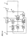
- Figure 14 is a block diagram illustrating the noise control system of this embodiment. Elements in the block diagram of Figure 14 corresponding to those illustrated in Embodiment 1 with reference to, e.g., Figure 1 have like reference numerals, and will not be further described below.
- the coefficient of the adaptive filter 4 is updated in an optimal manner according to the level of low frequency noise, in view of the output level of the adaptive filter 4 and the linearity of the control speaker 1 .
- the coefficient of the adaptive filter 4 is updated in an optimal manner according to the level of low frequency noise, in view of the output level of the adaptive filter 4 and the linearity of the control speaker 1 .
- the illustrated noise control system includes a signal level converter 13 for receiving a signal output from the digital filter 8 as an input.
- the output signal from the signal level converter 13 is multiplied by the output from the coefficient update calculator 9 at a multiplier 14 which is provided between the coefficient update calculator 9 and the adaptive filter 4 .
- the other elements and the functions thereof are similar to those described above in Embodiment 1.
- a low frequency component of the output signal of the adaptive filter 4 is obtained from the digital filter 8 as an output signal thereof.
- the control speaker 1 has a non-linear characteristic in the vicinity of such a low frequency
- the output sound pressure is saturated (see Figure 5 ) while the distortion increases considerably (see Figure 6 ), as illustrated in the input-output sound pressure characteristic of Figure 5 and the input-output sound pressure distortion characteristic of Figure 6 .
- noise corresponding to the broken line (a) in Figure 4
- the conventional adaptive filter 4 whose spectrum at the error detector (microphone) 2 includes signals in the vicinity of the low frequency f1, as illustrated by the broken line (a) in Figure 7
- a sufficient sound elimination cannot be realized because the control sound is saturated at the frequency f1. It may rather lead to generation of a higher harmonic wave distortion at a frequency twice or three times the frequency f1, as illustrated by a solid line (b) in Figure 7 , thereby creating new noise.
- the distortion may act as an error signal, thereby causing an adverse effect such as making the operation of the adaptive filter 4 unstable.
- the signal level converter 13 detects the level of the output signal from the digital filter 8, and performs a conversion operation for the detected signal level.
- the signal level converter 13 converts the level of the signal input thereto (i.e., the output signal from the digital filter 8 ) according to the input-output characteristic as illustrated in Figure 15 , which is obtained by normalizing the input-output sound pressure distortion characteristic illustrated in Figure 6 .
- the level-converted output signal is input to the multiplier 14, where it is multiplied by the output signal of the coefficient update calculator 9.
- the output signal of the coefficient update calculator 9 is multiplied by a small value which is output from the signal level converter 13.
- the output (the calculation result) from the coefficient update calculator 9 has substantially no influence on the update operation of the coefficient of the adaptive filter 4 , so that the coefficient of the adaptive filter 4 is updated according to the output from the coefficient update calculator 6.
- the control speaker 1 since the control speaker 1 operates in the linear region, it is possible to sufficiently control noise which contains a low frequency component (e.g., f1), as illustrated by the solid line (b) in Figure 4 .
- the coefficient of the adaptive filter 4 is updated based on the output (the calculation result) from the coefficient update calculator 9 after the multiplication operation.
- a low frequency gain of the adaptive filter 4 is suppressed so as to perform an optimal and stable noise control within the low frequency reproducibility of the control speaker 1 without inappropriately performing a control at the frequency f1, as illustrated by the solid line (b) in Figure 10 .
- Embodiments 1-3 above a structure including two coefficient update calculators has been illustrated.
- a single coefficient update calculator is used, while a low frequency band of the control signal is limited so that the adaptive filter does not generate an excessive control signal for noise having a frequency which is too low for the low band reproducibility of the control speaker, as in Embodiment 1.
- FIG 16 is a block diagram illustrating a structure of the noise control system of this embodiment.
- the noise control system includes a control speaker 1 , an error detection microphone 2 which functions as an error detector, a noise detection microphone 3 which functions as a noise detector, an adaptive filter 4 , a digital filter 5 which approximates the propagation characteristic between the control speaker 1 and the error detection microphone 2 , a coefficient update calculator 6 , digital filters 7 and 8 each having a frequency band limiting characteristic (band limiting filters), and a phase inverter 10 for inverting the output of the adaptive filter 4 .
- the noise control system of the present embodiment further includes an adder 111 for adding the output of the digital filter 8 and the output of the error detector 2 so as to provide the sum to the coefficient update calculator 6 , and another adder 112 for adding the output of the digital filter 5 and the output of the digital filter 7 so as to provide the sum to the coefficient update calculator 6 .
- noise generated from a noise source is detected by a noise detector 3 , and a noise source signal is generated based on the detection result.
- the generated noise source signal is processed by the adaptive filter 4 , so as to output a control signal.
- a control sound is generated from the control speaker 1 based on the control signal so that the control sound interferes with the noise from the noise source, thereby reducing the noise.
- the state of interference between the control sound output from the control speaker 1 and the noise is measured by the error detector (microphone) 2 .
- the output of the error detector (microphone) 2 should ideally be zero as a result of the noise control. Therefore, the coefficient update calculator 6 performs a coefficient update calculation as previously described in Expression (1) based on a filtered X-LMS method (see Widrow and Stearns, "Adaptive Signal Processing", 1985 ), or the like, so as to adjust the characteristic of the adaptive filter 4 , such that the output signal of the error detector (microphone) 2 is reduced. This changes the control sound actually generated from the control speaker 1 , thereby further reducing the noise.
- the frequency characteristic of the control speaker 1 is such that the sound pressure of an output thereof is reduced in a frequency region where the frequency is less than or equal to the lower limit reproducible frequency f L , as shown in Figure 2 .
- the coefficient gain of the adaptive filter 4 sufficiently reduces (or cancels) the noise in the low frequency region while compensating for the characteristic of the control speaker 1 , thereby converging into the characteristic as illustrated in Figure 3 , where the gain has an increase in the low frequency region (a region where the frequency is less than or equal to the lower limit reproducible frequency f L of the control speaker 1 ). In such a case, a large low frequency signal is input to the control speaker 1 .
- the distortion may act as an error signal, thereby causing an adverse effect such as making the operation of the adaptive filter 4 unstable.
- the digital filters 7 and 8 are set to have a band limiting characteristic with a passband characteristic as illustrated in Figure 17 in the low frequency region where the output of the control speaker 1 is reduced (e.g., the frequency region where the frequency is less than or equal to the lower limit reproducible frequency f L of the control speaker 1 ).
- the output signal of the adaptive filter 4 is inverted by the phase inverter 10 and processed by the digital filter 8 .
- the resulting signal is added to the error detection signal by the adder 111 , and the sum is input to the coefficient update calculator 6 .
- the output signal of the noise detector 3 is processed by the digital filter 7 .
- the resulting signal is added to the output signal of the digital filter 5 by the adder 112 , and the sum is input to the coefficient update calculator 6 .
- the gain in the passband of the digital filter 7 is set to be larger than the output signal level of the digital filter 5 .
- the gain in the passband of the digital filter 8 is set to be larger than the output signal level of the error detector.
- R j r j ⁇ r j - 1 ... r j - n - 1
- W j w ( 1 ⁇ ) j , w ( 2 ⁇ ) j , ... , w ( n ⁇ ) j
- S j s j ⁇ s j - 1 ... s j - n - 1 T .
- ⁇ W_all j denotes an output signal vector of the coefficient update calculator 6, W, a coefficient vector of the adaptive filter 4 , R j an output vector of the digital filter 5 , S j an output signal vector of the digital filter 7 , e j an output signal of the error detector, and v j an output signal of the digital filter 8, all at time j.
- n denotes the order of the adaptive filter 4
- ⁇ is a size parameter for a coefficient update step.
- the broken line (a) in Figure 9 is a coefficient gain of the adaptive filter 4 which is obtained by using only the output of the digital filter 5 and the output of the error detector 2 for updating the coefficient of the adaptive filter 4 .
- phase inverter 10 is connected between the adaptive filter 4 and the digital filter 8 .
- Functions and effects similar to those described above are also obtained by the structure as illustrated in Figure 18 , where the phase inverter 10 is connected between the noise detector 3 and the digital filter 7 .
- functions and effects similar to those described above are also obtained by a structure where the phase inverter 10 is connected to the output of the digital filter 8 or the digital filter 7 .
- a coefficient controller 144 having a gain of 1/a ⁇ 1 may be provided to the output of the digital filter 5 , while providing another coefficient controller 143 having a gain of 1/b ⁇ 1 to the output signal of the error detector 2 , as illustrated in Figure 20 .
- the coefficient update calculator 6 it is possible to provide the coefficient update calculator 6 with a signal whose frequency band, in which a relatively negative coefficient update is performed, is emphasized.
- Figure 21 is a block diagram illustrating a structure of the noise control system of this embodiment. Elements in the block diagram of Figure 21 corresponding to those illustrated in the previous Embodiments with reference to, e.g., Figure 1 have like reference numerals, and will not be further described below.
- a coefficient update calculation as described above in Embodiment 1 is performed when the low frequency component of the output of the adaptive filter 4 is at a small level and the control speaker 1 is operating in the linear region.
- a coefficient update calculation which suppresses the filter gain in the low frequency region is performed when the low frequency component of the output of the adaptive filter 4 increases and the control speaker 1 enters the non-linear region. In this way, it is possible not only to sufficiently reduce the noise even in the low frequency region when the noise level is low, but also to perform a stable noise control even when the noise level in the low frequency region is high.
- the noise control system illustrated in Figure 21 includes a selector 121 for selecting one of the output of the digital filter 5 and the output of the digital filter 7 , another selector 122 for selecting one of the output of the digital filter 8 and the output of the error detector 2 , and a selection control calculator 123 for controlling the operations of the selectors 121 and 122 .
- the other elements and the functions thereof are similar to those described above in Embodiment 1.
- a low frequency component of the output signal of the adaptive filter 4 is obtained from the digital filter 8 as an output signal thereof.
- the control speaker 1 has a non-linear characteristic in the vicinity of such a low frequency
- the output sound pressure is saturated (see Figure 5 ) while the distortion increases considerably (see Figure 6 ), as illustrated in the input-output sound pressure characteristic of Figure 5 and the input-output sound pressure distortion characteristic of Figure 6 .
- noise corresponding to the broken line (a) in Figure 4
- the conventional adaptive filter 4 whose spectrum at the error detector (microphone) 2 includes signals in the vicinity of the low frequency f1, as illustrated by the broken line (a) in Figure 7
- a sufficient sound elimination cannot be realized because the control sound is saturated at the frequency f1. It may rather lead to generation of a higher harmonic wave distortion at a frequency twice or three times the frequency f1, as illustrated by a solid line (b) in Figure 7 , thereby creating new noise.
- the distortion may act as an error signal, thereby causing an adverse effect such as making the operation of the adaptive filter 4 unstable.
- the selection control calculator 123 is used to detect the output level of the low frequency component in the output from the digital filter 8 . If the output level exceeds a predetermined level Ls, the selector 122 is controlled by the selection control calculator 123 so as to select the output of the digital filter 8 . The selector 121 is controlled by the selection control calculator 123 so as to select the output of the digital filter 7 .
- the selection control calculator 123 controls the selector 121 to select the output of the digital filter 5 and the selector 122 to select the output of the error detector 2 .
- the control speaker 1 operates in the linear region when the low frequency component of the control speaker 1 is at a small level, thereby sufficiently controlling noise which contains a low frequency component (e.g., f1), as illustrated by the solid line (b) in Figure 4 .
- a low frequency component e.g., f1
- the level of the low frequency component of the adaptive filter 4 increases and the input to the control speaker 1 exceeds the threshold level Ls to enter the non-linear region, the update operation of the coefficient of the adaptive filter 4 is restricted so as to reduce the low frequency gain.
- noise control system of the present embodiment it is possible to effectively utilize the linear operability of the control speaker 1 while suppressing the operation thereof in the non-linear region, so as to provide an optimal noise control for low frequency level noise.
- one of the output of the digital filter 8 and the output of the error detector 2 is always selected by the selector 122 , while one of the output of the digital filter 5 and the output of the digital filter 7 is always selected by the selector 121 .
- each of the selectors 121 and 122 may perform a thinning-out operation on the outputs at an appropriate thinning-out frequency.
- the selector 122 may operate to transfer the output of the error detector 2 to the coefficient update calculator 6 only at one timing out of 16 transfer timings, while transferring nothing to the coefficient update calculator 6 at the other transfer timings (thus, the outputs of the error detector 2 to be transferred are thinned out), and to transfer the output of the digital filter 8 to the coefficient update calculator 6 only at one timing out of 4 transfer timings, while transferring nothing to the coefficient update calculator 6 at the other transfer timings (thus, the outputs of the digital filter 8 to be transferred are thinned out).
- the selector 121 also operates in a manner similar to that of the selector 122 regarding the selection of the outputs from the digital filters 5 and 7 . In this way, the coefficient of the adaptive filter 4 is updated in the negative direction.
- the above-described operations of the selectors 121 and 122 and the frequency of such operations may be controlled by the selection control calculator 123 .
- the digital filter is set in the low frequency region (e.g., the frequency region where the frequency is less than or equal to the lower limit reproducible frequency f L of the control speaker 1 ) in order to suppress the non-linear distortion of the control speaker 1 in the low frequency region.
- the frequency band setting of the present invention is not limited thereto, and the coefficient update operation of the adaptive filter 4 having any frequency band can be suppressed by a method similar to that described above.
- the noise detection microphone 3 For example, where external noise, which cannot be detected by the noise detection microphone 3 , is introduced into the error detection microphone 2 , the correlation between the noise detection signal and the error detection signal is reduced at the frequency of the external noise. In such a case, the noise (external noise) may not be eliminated appropriately, and the adaptive filter 4 may even malfunction to produce abnormal oscillation at the frequency of the external noise. In order to prevent this, the passband of the digital filter may be set to coincide with the frequency of the external noise.
- the noise detection signal and the adaptive filter output signal are processed by the band limiting digital filters, which have the same characteristic, so as to produce a coefficient update signal in the negative direction from both of the output signals, thereby controlling the adaptive filter used in a noise control calculation.
- the present invention prevents an undesired increase in the coefficient gain of the adaptive filter in the band of the above-described digital filter, while realizing a coefficient control of the adaptive filter used in a noise control calculation without having to use additional hardware such as an adaptive filter or an additional calculation process, thereby realizing a stable noise processing operation.
- whether or not to perform the negative coefficient update for the adaptive filter is controlled in view of the non-linear characteristic of the noise propagation system or the control sound generator.
Landscapes
- Physics & Mathematics (AREA)
- Engineering & Computer Science (AREA)
- Acoustics & Sound (AREA)
- Multimedia (AREA)
- Soundproofing, Sound Blocking, And Sound Damping (AREA)
Claims (11)
- Système de régulation de bruit, comprenant :un générateur de son de régulation (1) pour générer un son de régulation;un détecteur d'erreur (2) pour détecter un signal d'erreur entre le son de régulation et le bruit ;un détecteur de bruit (3) pour détecter un signal de source de bruit ;un filtre adaptatif (4) pour délivrer en sortie un signal de régulation ; etun dispositif de mise à jour de coefficient pour mettre à jour un coefficient du filtre adaptatif (4), le dispositif de mise à jour de coefficient comprenant au moins un premier filtre numérique (5), un second filtre numérique (7), un troisième filtre numérique (8), un calculateur de mise à jour de coefficient (6), un inverseur de phase (10), un premier additionneur (112), et un second additionneur (111),caractérisé en ce que :le premier filtre numérique (5) reçoit, en tant qu'entrée, une sortie du détecteur de bruit (3) ;le premier additionneur (112) reçoit, en tant qu'entrées, une sortie du premier filtre numérique (5) et une sortie du second filtre numérique (7) ;le second additionneur (111) reçoit, en tant qu'entrées, une sortie du détecteur d'erreur (2) et une sortie du troisième filtre numérique (8) ;le premier filtre numérique (5) établit une approximation d'une caractéristique de propagation entre le générateur de son de régulation (1) et le détecteur d'erreur (2) ;le second (7) et le troisième (8) filtre numérique ont une caractéristique de fréquence de bande passante commune,le second filtre numérique (7) reçoit, en tant qu'entrée, la sortie du détecteur de bruit (3);l'inverseur de phase (10) inverse une sortie du filtre adaptatif (4) ;le troisième filtre numérique (8) reçoit, en tant qu'entrée, la sortie de l'inverseur de phase (10) ;le calculateur de mise à jour de coefficient (6) reçoit, en tant qu'entrée, une sortie du premier additionneur (112) et du second additionneur (111),et en ce que le calculateur de mise à jour de coefficient (6) effectue un calcul en utilisant la sortie du premier additionneur (112) et du second additionneur (111) de sorte que la sortie du second additionneur (111) soit réduite, et met à jour le coefficient du filtre adaptatif (4) sur la base du résultat du calcul, de sorte qu'une augmentation du gain de coefficient du filtre adaptatif (4) dans une bande de fréquence prédéterminée soit supprimée.
- Système de régulation de bruit, comprenant :un générateur de son de régulation (1) pour générer un son de régulation;un détecteur d'erreur (2) pour détecter un signal d'erreur entre le son de régulation et le bruit ;un détecteur de bruit (3) pour détecter un signal de source de bruit ;un filtre adaptatif (4) pour délivrer en sortie un signal de régulation ; etun dispositif de mise à jour de coefficient pour mettre à jour un coefficient du filtre adaptatif (4), le dispositif de mise à jour de coefficient comprenant au moins un premier filtre numérique (5), un second filtre numérique (7), un troisième filtre numérique (8), un calculateur de mise à jour de coefficient (6), un inverseur de phase (10), un premier additionneur (112), et un second additionneur (111),caractérisé en ce que :le premier filtre numérique (5) reçoit, en tant qu'entrée, une sortie du détecteur de bruit (3) ;le premier additionneur (112) reçoit, en tant qu'entrées, une sortie du premier filtre numérique (5) et une sortie du second filtre numérique (7) ;le second additionneur (111) reçoit, en tant qu'entrées, une sortie du détecteur d'erreur (2) et une sortie du troisième filtre numérique (8) ;le calculateur de mise à jour de coefficient (6) reçoit, en tant qu'entrées, une sortie du premier additionneur (112) et du second additionneur (111),le premier filtre numérique (5) établit une approximation d'une caractéristique de propagation entre le générateur de son de régulation (1) et le détecteur d'erreur (2) ;le second (7) et le troisième (8) filtre numérique ont une caractéristique de fréquence de bande passante commune,l'inverseur de phase (10) inverse une sortie du détecteur de bruit (3) ;le second filtre numérique (7) reçoit, en tant qu'entrée, la sortie de l'inverseur de phase (10) ;le troisième filtre numérique (8) reçoit, en tant qu'entrée, la sortie du filtre adaptatif (4) ;et en ce que le calculateur de mise à jour de coefficient (6) effectue un calcul en utilisant la sortie du premier additionneur (112) et du second additionneur (111) de sorte que la sortie du second additionneur (111) soit réduite, et met à jour le coefficient du filtre adaptatif (4) sur la base du résultat du calcul, de sorte qu'une augmentation du gain de coefficient du filtre adaptatif (4) dans une bande de fréquence prédéterminée soit supprimée.
- Système de régulation de bruit selon la revendication 1 ou la revendication 2, dans lequel :le dispositif de mise à jour de coefficient comprend en outre :dans lequel le premier facteur de coefficient et le second facteur de coefficient sont chacun fixés de façon à être égaux ou supérieurs à 1.un premier contrôleur de coefficient (114) pour multiplier une sortie du second filtre numérique (7) par un premier facteur de coefficient, le premier additionneur (112) recevant, en tant qu'entrées, une sortie du premier filtre numérique (5) et une sortie du premier contrôleur de coefficient (114), etun second contrôleur de coefficient (113) pour multiplier une sortie du troisième filtre numérique (8) par un second facteur de coefficient, le second additionneur (111) recevant, en tant qu'entrées, une sortie du détecteur d'erreur (2) et une sortie du second contrôleur de coefficient (113) ;
- Système de régulation de bruit selon la revendication 3, dans lequel le premier contrôleur de coefficient (114) est réglé de façon à ce que, dans une bande passante du second filtre numérique (7), la sortie du premier contrôleur de coefficient (114) soit supérieure à un signal de sortie du premier filtre numérique (5).
- Système de régulation de bruit selon la revendication 3, dans lequel le second contrôleur de coefficient (113) est réglé de façon à ce que, dans une bande passante du troisième filtre numérique (8), la sortie du second contrôleur de coefficient (113) soit supérieure à un signal de sortie du détecteur d'erreur (2).
- Système de régulation de bruit selon la revendication 1 ou la revendication 2, dans lequel :le dispositif de mise à jour de coefficient comprend en outre :dans lequel le premier facteur de coefficient et le second facteur de coefficient sont chacun fixés de façon à être inférieurs ou égaux à 1.un premier contrôleur de coefficient (114) pour multiplier une sortie du premier filtre numérique (5) par un premier facteur de coefficient (a), le premier additionneur (112) recevant, en tant qu'entrées, une sortie du premier contrôleur de coefficient (114) et une sortie du second filtre numérique (3) ; etun second contrôleur de coefficient (143) pour multiplier une sortie du détecteur d'erreur (2) par un second facteur de coefficient (b), le second additionneur (111) recevant, en tant qu'entrées, une sortie du second contrôleur de coefficient (143) et une sortie du troisième filtre numérique (8) ;
- Système de régulation de bruit selon la revendication 6, dans lequel le premier contrôleur de coefficient (144) est réglé de façon à ce que, dans une bande passante du second filtre numérique (7), la sortie du premier contrôleur de coefficient (144) soit inférieure à un signal de sortie du premier filtre numérique (5).
- Système de régulation de bruit selon la revendication 6, dans lequel le second contrôleur de coefficient (143) est réglé de façon à ce que, dans une bande passante du troisième filtre numérique (8), la sortie du second contrôleur de coefficient (143) soit inférieure à un signal de sortie du détecteur d'erreur (2).
- Système de régulation de bruit selon la revendication 1 ou la revendication 2, dans lequel la bande de fréquence prédéterminée se situe dans une région de basse fréquence.
- Système de régulation de bruit selon la revendication 9, dans lequel la bande de fréquence prédéterminée est une région de fréquence dans laquelle la fréquence est inférieure ou égale à une fréquence reproductible de limite inférieure du générateur de son de régulation (1).
- Système de régulation de bruit selon la revendication 1 ou la revendication 2, dans lequel la bande de fréquence prédéterminée se situe dans une région de fréquence où il existe une corrélation entre un signal de sortie du détecteur de bruit (3) et un signal de sortie du détecteur d'erreur (2).
Applications Claiming Priority (6)
| Application Number | Priority Date | Filing Date | Title |
|---|---|---|---|
| JP20236398 | 1998-07-16 | ||
| JP20236398 | 1998-07-16 | ||
| JP15877599 | 1999-06-04 | ||
| JP15877699A JP3359301B2 (ja) | 1999-06-04 | 1999-06-04 | 騒音制御装置 |
| JP15877699 | 1999-06-04 | ||
| JP11158775A JP2000089770A (ja) | 1998-07-16 | 1999-06-04 | 騒音制御装置 |
Publications (4)
| Publication Number | Publication Date |
|---|---|
| EP0973151A2 EP0973151A2 (fr) | 2000-01-19 |
| EP0973151A3 EP0973151A3 (fr) | 2003-01-02 |
| EP0973151B1 true EP0973151B1 (fr) | 2008-10-29 |
| EP0973151B8 EP0973151B8 (fr) | 2009-02-25 |
Family
ID=27321400
Family Applications (1)
| Application Number | Title | Priority Date | Filing Date |
|---|---|---|---|
| EP99113651A Expired - Lifetime EP0973151B8 (fr) | 1998-07-16 | 1999-07-14 | Arrangement de contrôle du bruit |
Country Status (3)
| Country | Link |
|---|---|
| US (1) | US6418228B1 (fr) |
| EP (1) | EP0973151B8 (fr) |
| DE (1) | DE69939796D1 (fr) |
Families Citing this family (99)
| Publication number | Priority date | Publication date | Assignee | Title |
|---|---|---|---|---|
| US7853024B2 (en) | 1997-08-14 | 2010-12-14 | Silentium Ltd. | Active noise control system and method |
| IL121555A (en) | 1997-08-14 | 2008-07-08 | Silentium Ltd | Active acoustic noise reduction system |
| US6724706B1 (en) * | 1999-02-26 | 2004-04-20 | Matsushita Electric Industrial Co., Ltd. | Digital adaptive equalizer for different quality signals |
| US6608904B1 (en) * | 1999-06-04 | 2003-08-19 | Telefonaktiebolaget Lm Ericsson (Publ) | Method and apparatus for canceling interference in a loudspeaker communication path through adaptive discrimination |
| WO2001006746A2 (fr) * | 1999-07-19 | 2001-01-25 | Oticon A/S | Annulation de signal en retour utilisant une detection de bande passante |
| JP3502594B2 (ja) * | 2000-05-24 | 2004-03-02 | 松下電器産業株式会社 | 車輌用能動騒音低減装置 |
| WO2004009007A1 (fr) * | 2002-07-19 | 2004-01-29 | The Penn State Research Foundation | Procede lineairement independant destine a la modelisation de voie secondaire en ligne non invasive |
| JP2004080210A (ja) * | 2002-08-13 | 2004-03-11 | Fujitsu Ltd | デジタルフィルタ |
| ATE395682T1 (de) * | 2002-10-21 | 2008-05-15 | Silentium Ltd | Aktivsystem zur reduktion des akustischen rauschens |
| US7613312B2 (en) * | 2003-05-30 | 2009-11-03 | Panasonic Corporation | Audio processing apparatus for implementing level corrections of audio data |
| JP4077383B2 (ja) * | 2003-09-10 | 2008-04-16 | 松下電器産業株式会社 | 能動型振動騒音制御装置 |
| JP2005252933A (ja) * | 2004-03-08 | 2005-09-15 | Matsushita Electric Ind Co Ltd | Amラジオ受信機 |
| EP1766261B1 (fr) * | 2004-06-10 | 2012-02-08 | Lord Corporation | Methode et systeme de regulation des vibrations d'un helicoptere |
| US8162606B2 (en) | 2004-08-30 | 2012-04-24 | Lord Corporation | Helicopter hub mounted vibration control and circular force generation systems for canceling vibrations |
| CN101022994B (zh) | 2004-08-30 | 2012-07-04 | 洛德公司 | 直升飞机振动控制系统和消除振动的旋转力发生器 |
| US8267652B2 (en) | 2004-08-30 | 2012-09-18 | Lord Corporation | Helicopter hub mounted vibration control and circular force generation systems for canceling vibrations |
| US7722322B2 (en) | 2004-08-30 | 2010-05-25 | Lord Corporation | Computer system and program product for controlling vibrations |
| US8090482B2 (en) * | 2007-10-25 | 2012-01-03 | Lord Corporation | Distributed active vibration control systems and rotary wing aircraft with suppressed vibrations |
| JP2006270661A (ja) * | 2005-03-25 | 2006-10-05 | Yokogawa Electric Corp | Σδアナログ/デジタル変換器 |
| WO2007010727A1 (fr) * | 2005-07-15 | 2007-01-25 | Nec Corporation | Filtre numerique adaptatif, procede traitement de signaux, recepteur mf, et programme |
| US8027484B2 (en) * | 2005-07-27 | 2011-09-27 | Panasonic Corporation | Active vibration noise controller |
| JP4322916B2 (ja) * | 2006-12-26 | 2009-09-02 | 本田技研工業株式会社 | 能動型振動騒音制御装置 |
| US8855329B2 (en) | 2007-01-22 | 2014-10-07 | Silentium Ltd. | Quiet fan incorporating active noise control (ANC) |
| GB0725111D0 (en) | 2007-12-21 | 2008-01-30 | Wolfson Microelectronics Plc | Lower rate emulation |
| GB0725108D0 (en) * | 2007-12-21 | 2008-01-30 | Wolfson Microelectronics Plc | Slow rate adaption |
| GB0725112D0 (en) * | 2007-12-21 | 2008-01-30 | Wolfson Microelectronics Plc | Adapting cut-off frequency |
| JP4506873B2 (ja) * | 2008-05-08 | 2010-07-21 | ソニー株式会社 | 信号処理装置、信号処理方法 |
| US8073151B2 (en) * | 2009-04-28 | 2011-12-06 | Bose Corporation | Dynamically configurable ANR filter block topology |
| CN103996398B (zh) * | 2009-04-28 | 2017-05-24 | 伯斯有限公司 | 声音相关的anr信号处理调节 |
| US8090114B2 (en) * | 2009-04-28 | 2012-01-03 | Bose Corporation | Convertible filter |
| US8184822B2 (en) * | 2009-04-28 | 2012-05-22 | Bose Corporation | ANR signal processing topology |
| US8315405B2 (en) * | 2009-04-28 | 2012-11-20 | Bose Corporation | Coordinated ANR reference sound compression |
| US8073150B2 (en) * | 2009-04-28 | 2011-12-06 | Bose Corporation | Dynamically configurable ANR signal processing topology |
| US8532310B2 (en) | 2010-03-30 | 2013-09-10 | Bose Corporation | Frequency-dependent ANR reference sound compression |
| US8165313B2 (en) * | 2009-04-28 | 2012-04-24 | Bose Corporation | ANR settings triple-buffering |
| US8472637B2 (en) | 2010-03-30 | 2013-06-25 | Bose Corporation | Variable ANR transform compression |
| US8085946B2 (en) * | 2009-04-28 | 2011-12-27 | Bose Corporation | ANR analysis side-chain data support |
| US8611553B2 (en) | 2010-03-30 | 2013-12-17 | Bose Corporation | ANR instability detection |
| US8345888B2 (en) * | 2009-04-28 | 2013-01-01 | Bose Corporation | Digital high frequency phase compensation |
| US8737636B2 (en) | 2009-07-10 | 2014-05-27 | Qualcomm Incorporated | Systems, methods, apparatus, and computer-readable media for adaptive active noise cancellation |
| JP5867389B2 (ja) * | 2010-05-24 | 2016-02-24 | 日本電気株式会社 | 信号処理方法、情報処理装置、及び信号処理プログラム |
| WO2012075343A2 (fr) | 2010-12-03 | 2012-06-07 | Cirrus Logic, Inc. | Contrôle de supervision d'un circuit d'annulation de bruit adaptatif dans un dispositif audio personnel |
| US8908877B2 (en) | 2010-12-03 | 2014-12-09 | Cirrus Logic, Inc. | Ear-coupling detection and adjustment of adaptive response in noise-canceling in personal audio devices |
| CN103607982B (zh) | 2011-05-11 | 2016-10-12 | 塞伦蒂姆公司 | 噪声控制的装置、系统和方法 |
| US9928824B2 (en) | 2011-05-11 | 2018-03-27 | Silentium Ltd. | Apparatus, system and method of controlling noise within a noise-controlled volume |
| US9214150B2 (en) | 2011-06-03 | 2015-12-15 | Cirrus Logic, Inc. | Continuous adaptation of secondary path adaptive response in noise-canceling personal audio devices |
| US9318094B2 (en) | 2011-06-03 | 2016-04-19 | Cirrus Logic, Inc. | Adaptive noise canceling architecture for a personal audio device |
| US8948407B2 (en) | 2011-06-03 | 2015-02-03 | Cirrus Logic, Inc. | Bandlimiting anti-noise in personal audio devices having adaptive noise cancellation (ANC) |
| US9076431B2 (en) | 2011-06-03 | 2015-07-07 | Cirrus Logic, Inc. | Filter architecture for an adaptive noise canceler in a personal audio device |
| US8958571B2 (en) | 2011-06-03 | 2015-02-17 | Cirrus Logic, Inc. | MIC covering detection in personal audio devices |
| US9824677B2 (en) * | 2011-06-03 | 2017-11-21 | Cirrus Logic, Inc. | Bandlimiting anti-noise in personal audio devices having adaptive noise cancellation (ANC) |
| US8848936B2 (en) | 2011-06-03 | 2014-09-30 | Cirrus Logic, Inc. | Speaker damage prevention in adaptive noise-canceling personal audio devices |
| US8811602B2 (en) * | 2011-06-30 | 2014-08-19 | Broadcom Corporation | Full duplex speakerphone design using acoustically compensated speaker distortion |
| US9325821B1 (en) * | 2011-09-30 | 2016-04-26 | Cirrus Logic, Inc. | Sidetone management in an adaptive noise canceling (ANC) system including secondary path modeling |
| US9142205B2 (en) | 2012-04-26 | 2015-09-22 | Cirrus Logic, Inc. | Leakage-modeling adaptive noise canceling for earspeakers |
| US9014387B2 (en) | 2012-04-26 | 2015-04-21 | Cirrus Logic, Inc. | Coordinated control of adaptive noise cancellation (ANC) among earspeaker channels |
| US9318090B2 (en) | 2012-05-10 | 2016-04-19 | Cirrus Logic, Inc. | Downlink tone detection and adaptation of a secondary path response model in an adaptive noise canceling system |
| US9123321B2 (en) | 2012-05-10 | 2015-09-01 | Cirrus Logic, Inc. | Sequenced adaptation of anti-noise generator response and secondary path response in an adaptive noise canceling system |
| US9076427B2 (en) | 2012-05-10 | 2015-07-07 | Cirrus Logic, Inc. | Error-signal content controlled adaptation of secondary and leakage path models in noise-canceling personal audio devices |
| US9319781B2 (en) | 2012-05-10 | 2016-04-19 | Cirrus Logic, Inc. | Frequency and direction-dependent ambient sound handling in personal audio devices having adaptive noise cancellation (ANC) |
| US9082387B2 (en) | 2012-05-10 | 2015-07-14 | Cirrus Logic, Inc. | Noise burst adaptation of secondary path adaptive response in noise-canceling personal audio devices |
| US9532139B1 (en) | 2012-09-14 | 2016-12-27 | Cirrus Logic, Inc. | Dual-microphone frequency amplitude response self-calibration |
| US9107010B2 (en) | 2013-02-08 | 2015-08-11 | Cirrus Logic, Inc. | Ambient noise root mean square (RMS) detector |
| US9369798B1 (en) | 2013-03-12 | 2016-06-14 | Cirrus Logic, Inc. | Internal dynamic range control in an adaptive noise cancellation (ANC) system |
| US9106989B2 (en) | 2013-03-13 | 2015-08-11 | Cirrus Logic, Inc. | Adaptive-noise canceling (ANC) effectiveness estimation and correction in a personal audio device |
| US9215749B2 (en) | 2013-03-14 | 2015-12-15 | Cirrus Logic, Inc. | Reducing an acoustic intensity vector with adaptive noise cancellation with two error microphones |
| US9414150B2 (en) | 2013-03-14 | 2016-08-09 | Cirrus Logic, Inc. | Low-latency multi-driver adaptive noise canceling (ANC) system for a personal audio device |
| US9635480B2 (en) | 2013-03-15 | 2017-04-25 | Cirrus Logic, Inc. | Speaker impedance monitoring |
| US9324311B1 (en) | 2013-03-15 | 2016-04-26 | Cirrus Logic, Inc. | Robust adaptive noise canceling (ANC) in a personal audio device |
| US9208771B2 (en) | 2013-03-15 | 2015-12-08 | Cirrus Logic, Inc. | Ambient noise-based adaptation of secondary path adaptive response in noise-canceling personal audio devices |
| US9467776B2 (en) | 2013-03-15 | 2016-10-11 | Cirrus Logic, Inc. | Monitoring of speaker impedance to detect pressure applied between mobile device and ear |
| US10206032B2 (en) | 2013-04-10 | 2019-02-12 | Cirrus Logic, Inc. | Systems and methods for multi-mode adaptive noise cancellation for audio headsets |
| US9066176B2 (en) | 2013-04-15 | 2015-06-23 | Cirrus Logic, Inc. | Systems and methods for adaptive noise cancellation including dynamic bias of coefficients of an adaptive noise cancellation system |
| US9462376B2 (en) | 2013-04-16 | 2016-10-04 | Cirrus Logic, Inc. | Systems and methods for hybrid adaptive noise cancellation |
| US9478210B2 (en) | 2013-04-17 | 2016-10-25 | Cirrus Logic, Inc. | Systems and methods for hybrid adaptive noise cancellation |
| US9460701B2 (en) | 2013-04-17 | 2016-10-04 | Cirrus Logic, Inc. | Systems and methods for adaptive noise cancellation by biasing anti-noise level |
| US9578432B1 (en) | 2013-04-24 | 2017-02-21 | Cirrus Logic, Inc. | Metric and tool to evaluate secondary path design in adaptive noise cancellation systems |
| US9264808B2 (en) | 2013-06-14 | 2016-02-16 | Cirrus Logic, Inc. | Systems and methods for detection and cancellation of narrow-band noise |
| US9392364B1 (en) | 2013-08-15 | 2016-07-12 | Cirrus Logic, Inc. | Virtual microphone for adaptive noise cancellation in personal audio devices |
| US9666176B2 (en) | 2013-09-13 | 2017-05-30 | Cirrus Logic, Inc. | Systems and methods for adaptive noise cancellation by adaptively shaping internal white noise to train a secondary path |
| US9704470B2 (en) | 2013-10-02 | 2017-07-11 | Universiti Putra Malaysia | Method and apparatus for nonlinear compensation in an active noise control system |
| US9620101B1 (en) | 2013-10-08 | 2017-04-11 | Cirrus Logic, Inc. | Systems and methods for maintaining playback fidelity in an audio system with adaptive noise cancellation |
| US10382864B2 (en) | 2013-12-10 | 2019-08-13 | Cirrus Logic, Inc. | Systems and methods for providing adaptive playback equalization in an audio device |
| US9704472B2 (en) | 2013-12-10 | 2017-07-11 | Cirrus Logic, Inc. | Systems and methods for sharing secondary path information between audio channels in an adaptive noise cancellation system |
| US10219071B2 (en) | 2013-12-10 | 2019-02-26 | Cirrus Logic, Inc. | Systems and methods for bandlimiting anti-noise in personal audio devices having adaptive noise cancellation |
| US9369557B2 (en) | 2014-03-05 | 2016-06-14 | Cirrus Logic, Inc. | Frequency-dependent sidetone calibration |
| US9479860B2 (en) | 2014-03-07 | 2016-10-25 | Cirrus Logic, Inc. | Systems and methods for enhancing performance of audio transducer based on detection of transducer status |
| US9648410B1 (en) | 2014-03-12 | 2017-05-09 | Cirrus Logic, Inc. | Control of audio output of headphone earbuds based on the environment around the headphone earbuds |
| US9319784B2 (en) | 2014-04-14 | 2016-04-19 | Cirrus Logic, Inc. | Frequency-shaped noise-based adaptation of secondary path adaptive response in noise-canceling personal audio devices |
| US9609416B2 (en) | 2014-06-09 | 2017-03-28 | Cirrus Logic, Inc. | Headphone responsive to optical signaling |
| US10181315B2 (en) | 2014-06-13 | 2019-01-15 | Cirrus Logic, Inc. | Systems and methods for selectively enabling and disabling adaptation of an adaptive noise cancellation system |
| US9478212B1 (en) | 2014-09-03 | 2016-10-25 | Cirrus Logic, Inc. | Systems and methods for use of adaptive secondary path estimate to control equalization in an audio device |
| US9552805B2 (en) | 2014-12-19 | 2017-01-24 | Cirrus Logic, Inc. | Systems and methods for performance and stability control for feedback adaptive noise cancellation |
| US10026388B2 (en) | 2015-08-20 | 2018-07-17 | Cirrus Logic, Inc. | Feedback adaptive noise cancellation (ANC) controller and method having a feedback response partially provided by a fixed-response filter |
| US9578415B1 (en) | 2015-08-21 | 2017-02-21 | Cirrus Logic, Inc. | Hybrid adaptive noise cancellation system with filtered error microphone signal |
| US10013966B2 (en) | 2016-03-15 | 2018-07-03 | Cirrus Logic, Inc. | Systems and methods for adaptive active noise cancellation for multiple-driver personal audio device |
| US10741165B2 (en) * | 2018-08-31 | 2020-08-11 | Bose Corporation | Systems and methods for noise-cancellation with shaping and weighting filters |
| US11074903B1 (en) * | 2020-03-30 | 2021-07-27 | Amazon Technologies, Inc. | Audio device with adaptive equalization |
| JPWO2023090120A1 (fr) * | 2021-11-18 | 2023-05-25 |
Family Cites Families (13)
| Publication number | Priority date | Publication date | Assignee | Title |
|---|---|---|---|---|
| EP0517525A3 (en) * | 1991-06-06 | 1993-12-08 | Matsushita Electric Industrial Co Ltd | Noise suppressor |
| JP3089082B2 (ja) | 1991-07-10 | 2000-09-18 | シャープ株式会社 | 適応型ディジタルフィルタ |
| EP0525456B1 (fr) * | 1991-07-10 | 1996-11-06 | Sharp Kabushiki Kaisha | Système utilisant plusieurs filtres numériques adaptatifs |
| US5337366A (en) * | 1992-07-07 | 1994-08-09 | Sharp Kabushiki Kaisha | Active control apparatus using adaptive digital filter |
| US5278913A (en) * | 1992-07-28 | 1994-01-11 | Nelson Industries, Inc. | Active acoustic attenuation system with power limiting |
| JP2924496B2 (ja) * | 1992-09-30 | 1999-07-26 | 松下電器産業株式会社 | 騒音制御装置 |
| JPH06202669A (ja) * | 1992-12-28 | 1994-07-22 | Toshiba Corp | 能動消音装置 |
| JP2856625B2 (ja) * | 1993-03-17 | 1999-02-10 | 株式会社東芝 | 適応形能動消音装置 |
| US5586189A (en) | 1993-12-14 | 1996-12-17 | Digisonix, Inc. | Active adaptive control system with spectral leak |
| JP3685503B2 (ja) * | 1994-03-30 | 2005-08-17 | 三洋電機株式会社 | 電子消音装置 |
| US5586190A (en) | 1994-06-23 | 1996-12-17 | Digisonix, Inc. | Active adaptive control system with weight update selective leakage |
| US5715320A (en) * | 1995-08-21 | 1998-02-03 | Digisonix, Inc. | Active adaptive selective control system |
| US5710822A (en) | 1995-11-07 | 1998-01-20 | Digisonix, Inc. | Frequency selective active adaptive control system |
-
1999
- 1999-07-14 DE DE69939796T patent/DE69939796D1/de not_active Expired - Lifetime
- 1999-07-14 EP EP99113651A patent/EP0973151B8/fr not_active Expired - Lifetime
- 1999-07-15 US US09/353,667 patent/US6418228B1/en not_active Expired - Fee Related
Also Published As
| Publication number | Publication date |
|---|---|
| EP0973151B8 (fr) | 2009-02-25 |
| DE69939796D1 (de) | 2008-12-11 |
| US6418228B1 (en) | 2002-07-09 |
| EP0973151A3 (fr) | 2003-01-02 |
| EP0973151A2 (fr) | 2000-01-19 |
Similar Documents
| Publication | Publication Date | Title |
|---|---|---|
| EP0973151B1 (fr) | Arrangement de contrôle du bruit | |
| JP2000089770A (ja) | 騒音制御装置 | |
| KR100238630B1 (ko) | 잡음 저감 장치 | |
| EP0578212B1 (fr) | Dispositif de commande active avec un filtre digital adaptif | |
| US6847721B2 (en) | Active noise control system with on-line secondary path modeling | |
| JP3089082B2 (ja) | 適応型ディジタルフィルタ | |
| EP1480494B1 (fr) | Suppression de l'effet Larsen lors du traitement du signal audio utilisant une transposition de fréquence | |
| EP0558312B1 (fr) | Circuit adaptatif de réduction de bruit pour un système de reproduction sonore | |
| EP2080408B1 (fr) | Évitement d'entrainement a filtre auto-régressif | |
| US7974428B2 (en) | Hearing aid with acoustic feedback suppression | |
| Shen et al. | Multi-channel wireless hybrid active noise control with fixed-adaptive control selection | |
| JPH03274897A (ja) | 電子消音方法及び装置 | |
| US7739321B2 (en) | Method and adaptive filter for processing a sequence of input data | |
| JP4860712B2 (ja) | 適応フィードバック抑制を伴う補聴器 | |
| US12273692B2 (en) | Public address device, howling suppression device, and howling suppression method | |
| EP3948846B1 (fr) | Commande de saturation de signal d'annulation de bruit | |
| JP3359301B2 (ja) | 騒音制御装置 | |
| EP0525456B1 (fr) | Système utilisant plusieurs filtres numériques adaptatifs | |
| EP1308926B1 (fr) | Système actif de suppression du bruit avec contrôle de la réponse en fréquence | |
| Airimitoaie et al. | Dynamic variable step size LMS adaptation algorithms—Application to adaptive feedforward noise attenuation | |
| JP3598617B2 (ja) | サイドローブキャンセラ | |
| JPH05158494A (ja) | ノイズ低減装置 | |
| JP2019203919A (ja) | ノイズ除去装置 | |
| JP3363254B2 (ja) | 騒音制御装置 | |
| JP3269098B2 (ja) | 騒音制御装置 |
Legal Events
| Date | Code | Title | Description |
|---|---|---|---|
| PUAI | Public reference made under article 153(3) epc to a published international application that has entered the european phase |
Free format text: ORIGINAL CODE: 0009012 |
|
| AK | Designated contracting states |
Kind code of ref document: A2 Designated state(s): AT BE CH CY DE DK ES FI FR GB GR IE IT LI LU MC NL PT SE |
|
| AX | Request for extension of the european patent |
Free format text: AL;LT;LV;MK;RO;SI |
|
| PUAL | Search report despatched |
Free format text: ORIGINAL CODE: 0009013 |
|
| AK | Designated contracting states |
Kind code of ref document: A3 Designated state(s): AT BE CH CY DE DK ES FI FR GB GR IE IT LI LU MC NL PT SE |
|
| AX | Request for extension of the european patent |
Free format text: AL;LT;LV;MK;RO;SI |
|
| 17P | Request for examination filed |
Effective date: 20030307 |
|
| AKX | Designation fees paid |
Designated state(s): DE FR GB |
|
| 17Q | First examination report despatched |
Effective date: 20041227 |
|
| GRAP | Despatch of communication of intention to grant a patent |
Free format text: ORIGINAL CODE: EPIDOSNIGR1 |
|
| GRAS | Grant fee paid |
Free format text: ORIGINAL CODE: EPIDOSNIGR3 |
|
| GRAA | (expected) grant |
Free format text: ORIGINAL CODE: 0009210 |
|
| AK | Designated contracting states |
Kind code of ref document: B1 Designated state(s): DE FR GB |
|
| REG | Reference to a national code |
Ref country code: GB Ref legal event code: FG4D |
|
| RAP2 | Party data changed (patent owner data changed or rights of a patent transferred) |
Owner name: PANASONIC CORPORATION |
|
| REF | Corresponds to: |
Ref document number: 69939796 Country of ref document: DE Date of ref document: 20081211 Kind code of ref document: P |
|
| RIN2 | Information on inventor provided after grant (corrected) |
Inventor name: KAKUHARI, ISAO Inventor name: HASHIMOTO, HIROYUKI Inventor name: TERAI, KENICHI |
|
| PLBE | No opposition filed within time limit |
Free format text: ORIGINAL CODE: 0009261 |
|
| STAA | Information on the status of an ep patent application or granted ep patent |
Free format text: STATUS: NO OPPOSITION FILED WITHIN TIME LIMIT |
|
| 26N | No opposition filed |
Effective date: 20090730 |
|
| PGFP | Annual fee paid to national office [announced via postgrant information from national office to epo] |
Ref country code: FR Payment date: 20110727 Year of fee payment: 13 |
|
| PGFP | Annual fee paid to national office [announced via postgrant information from national office to epo] |
Ref country code: DE Payment date: 20110706 Year of fee payment: 13 Ref country code: GB Payment date: 20110713 Year of fee payment: 13 |
|
| GBPC | Gb: european patent ceased through non-payment of renewal fee |
Effective date: 20120714 |
|
| REG | Reference to a national code |
Ref country code: FR Ref legal event code: ST Effective date: 20130329 |
|
| PG25 | Lapsed in a contracting state [announced via postgrant information from national office to epo] |
Ref country code: DE Free format text: LAPSE BECAUSE OF NON-PAYMENT OF DUE FEES Effective date: 20130201 Ref country code: GB Free format text: LAPSE BECAUSE OF NON-PAYMENT OF DUE FEES Effective date: 20120714 Ref country code: FR Free format text: LAPSE BECAUSE OF NON-PAYMENT OF DUE FEES Effective date: 20120731 |
|
| REG | Reference to a national code |
Ref country code: DE Ref legal event code: R119 Ref document number: 69939796 Country of ref document: DE Effective date: 20130201 |