EP0973226B1 - Richtkoppler, Antennenanordnung, und Übertragungs-Empfangsanordnung - Google Patents
Richtkoppler, Antennenanordnung, und Übertragungs-Empfangsanordnung Download PDFInfo
- Publication number
- EP0973226B1 EP0973226B1 EP99113099A EP99113099A EP0973226B1 EP 0973226 B1 EP0973226 B1 EP 0973226B1 EP 99113099 A EP99113099 A EP 99113099A EP 99113099 A EP99113099 A EP 99113099A EP 0973226 B1 EP0973226 B1 EP 0973226B1
- Authority
- EP
- European Patent Office
- Prior art keywords
- transmission line
- antenna device
- line
- antenna
- directional coupler
- Prior art date
- Legal status (The legal status is an assumption and is not a legal conclusion. Google has not performed a legal analysis and makes no representation as to the accuracy of the status listed.)
- Expired - Lifetime
Links
- 230000005540 biological transmission Effects 0.000 claims description 164
- 230000005855 radiation Effects 0.000 claims description 27
- 239000004020 conductor Substances 0.000 description 34
- 230000008878 coupling Effects 0.000 description 17
- 238000010168 coupling process Methods 0.000 description 17
- 238000005859 coupling reaction Methods 0.000 description 17
- 239000000758 substrate Substances 0.000 description 14
- 238000000034 method Methods 0.000 description 10
- 238000001514 detection method Methods 0.000 description 6
- 238000005259 measurement Methods 0.000 description 6
- 235000021251 pulses Nutrition 0.000 description 6
- 238000010586 diagram Methods 0.000 description 5
- 235000010627 Phaseolus vulgaris Nutrition 0.000 description 1
- 244000046052 Phaseolus vulgaris Species 0.000 description 1
- 230000002457 bidirectional effect Effects 0.000 description 1
- 230000010355 oscillation Effects 0.000 description 1
- 230000000644 propagated effect Effects 0.000 description 1
Images


Classifications
-
- H—ELECTRICITY
- H01—ELECTRIC ELEMENTS
- H01P—WAVEGUIDES; RESONATORS, LINES, OR OTHER DEVICES OF THE WAVEGUIDE TYPE
- H01P5/00—Coupling devices of the waveguide type
- H01P5/12—Coupling devices having more than two ports
- H01P5/16—Conjugate devices, i.e. devices having at least one port decoupled from one other port
- H01P5/18—Conjugate devices, i.e. devices having at least one port decoupled from one other port consisting of two coupled guides, e.g. directional couplers
Definitions
- the present invention relates to a directional coupler, an antenna device, and a transmitting - receiving device which are useful for a radar or the like with which the distance to an detection object or a relative velocity for the object is measured by transmission - reception of an electromagnetic wave in the millimetric wave band.
- the transmitting - receiving device of the millimetric wave radar of the above type includes a module which comprises a millimetric wave oscillator, a circulator, a directional coupler, a mixer, an antenna, and so forth which are integrated together, and is attached to the front or rear of the vehicle.
- FIG. 25 is a block diagram showing the overall configuration of the millimetric radar.
- the transmitting - receiving device and the antenna shown in FIG. 26 are attached to the front of the vehicle, and ordinarily, the signal processing device is provided in an optional location.
- the signal processing section of the signal processing device the distance to and the relative velocity for the vehicle running ahead are extracted as numerical information by means of the transmitting - receiving device.
- the control - alarm section based on the velocity of the vehicle running after and the distance between both the vehicles, an alarm is given when predetermined conditions are satisfied, or when the relative velocity for the vehicle running ahead exceeds a predetermined threshold.
- the directivity of the antenna is fixed. Therefore, there occurs the case that the desired detection or measurement is not performed depending on conditions. More particularly, for example, if vehicles run in plural traffic lanes as shown in FIG. 27, it can not immediately be determined whether a vehicle running ahead is present in the lane where the vehicle is running after, based on only the received electromagnetic wave reflected from the vehicle running ahead. More particularly, as shown in FIG. 27, when an electromagnetic wave is sent from a vehicle Cm by use of a radiation beam designated by the reference character B2, a reflected wave from the vehicle Ca running ahead, together with a reflected wave from a vehicle Cb running in the opposite lane, is received.
- the determined relative velocity is unduly high, due to the reflected wave from the vehicle running in the opposite lane.
- an error alarm is given.
- FIG. 28 even if an electromagnetic wave is sent forward from the vehicle Cm by use of the radiation beam designated by the reference character B1, the vehicle Ca running ahead in the lane where the vehicle is running after can not be detected.
- FIG. 29 even if an electromagnetic wave is sent forward from the vehicle Cm by use of the radiation beam designated by B1, the vehicle Ca running ahead can not be detected.
- the above-described problems can be dissolved by varying the direction of the radiation beam.
- the two detection objects running ahead and adjacent in the angular directions can be separately detected.
- the curve of the lane is judged, and the radiation beam is directed in the direction in dependence on the judgement, for example, the radiation beam is directed to the direction indicated by the reference character B2, and thereby, the vehicle Ca running ahead can be detected.
- the hilly situation of the road is judged, and for example, the radiation beam is directed upwardly, namely, to the direction designated by the reference numeral B2, and thereby, the vehicle Ca running ahead can be detected.
- the whole of a casing containing the transmitting - receiving device including the antenna is rotated only with a motor or the like to change (tilt) the direction of the radiation beam. Accordingly, the whole of the device is large in size, and it is difficult to scan with the radiation beam while the direction of the radiation is changed at a high speed.
- GB 1272567 describes a microwave directional coupler wherein a transmission line and an active portion of a strip line are arranged parallel to each other. The magnitude of the output is changed by varying the gap between the active portion of the strip line and the transmission line.
- US-2,751,556 shows a microwave energy transmission device wherein a fist wave guide and a second wave guide are arranged parallel to each other.
- the first and second transmission lines comprise openings for providing the coupling between the same.
- US-3,166,723 describes a microwave device having a bidirectional variable coupler.
- the coupler comprises a main body provided by a frame and electrical elements comprising a top plate and a bottom plate.
- Four terminal conductors are coupled to the frame for providing input signals and deriving output signals.
- a movable coupling section formed by a slab line conductor connects the sender conductors of two of the terminal conductors.
- the movable coupling element is arranged to be transversally movable from the end to the fixed sender conductor coupling the sender conductors of two of the terminal conductors.
- US-3,195,075 describes a variable directional coupler having a stationary base plate and a movable frame consisting of two side plates, a front plate, a support plate, and an upper plate.
- a primary conductor is connected to the upper plate whereas a secondary conductor line is connected to the base plate.
- the prior, non-prepublished EP 0971435 A2 and the prior, non-prepublished EP 0969548 A2 disclose an antenna device having a directional coupler having a fixed transmission line and a moveable transmission line with linearly extending adjacent portions.
- the antenna device further comprises a primary radiator coupled to the second transmission line.
- the primary radiator comprises a columnar dielectric resonator having a tapered concentric opening.
- a directional coupler comprising a first microstrip line and a second microstrip line adjacent to the first microstrip line, the relative positions of the first microstrip line and the second microstrip line being changeable.
- a directional coupler comprising a first strip line, a second strip line adjacent to the first strip line, the relative positions of the first strip line and the second strip line being changeable.
- a directional coupler comprising a first slot line and a second slot line adjacent to the first slot line, the relative positions of the first slot line and the second slot line being changeable.
- a directional coupler comprising a first coplanar line and a second coplanar line adjacent to the first coplanar line, the relative positions of the first coplanar line and the second coplanar line being changeable.
- a directional coupler comprising a first wave guide and a second wave guide adjacent to the first wave guide, the relative positions of the first coplanar line and the second coplanar line being changeable.
- a directional coupler comprising a first suspended line and a second suspended line adjacent to the first suspended line, the relative positions of the first suspended line and the second suspended line being changeable.
- the directional coupler of which the relative positions of the two transmission lines can be changed while the coupling of the two transmission lines is kept.
- an antenna device including the directional coupler according to any one of the first through sixth aspects of the present invention, a primary radiator coupled or connected to a part of the directional coupler, and a driving mechanism for driving the directional coupler and the primary radiator.
- a transmitting - receiving device including the antenna device according to the seventh aspect of the present invention, and a transmitting - receiving circuit connected to the antenna device.
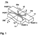
- FIG. 1 is a perspective view of the antenna device of the first embodiment.
- an antenna device 10a of the instant embodiment is composed of a directional coupler and a primary radiator.
- the directional coupler comprises a first transmission line 20a which consists of a microstrip line in which a line conductor 12 is formed on one of the main-faces of a dielectric substrate 11, and a ground conductor 13 (not shown in FIG. 1) is formed on the back side of the main-faces, and a second transmission line 30a which consists of a microstrip line formed in a similar manner.
- the primary radiator consists of a patch antenna 14a connected to the second transmission line 30a.
- the first transmission line 20a and the second transmission line 30a contain their portions which are linearly adjacent to each other.
- the two transmission lines are coupled to each other, and function as the directional coupler. More particularly, by designing properly, a half of a signal input through a port 2 can be output through a port 4, and the remaining half of the signal can be output through a port 1.
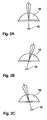
- the first transmission line 20a is fixed, while a driving mechanism (not shown FIG. 1) employing a voice coil motor, a pulse motor, or the like is attached to the second transmission line 30a, and thereby, the second transmission line 30a can be shifted in the direction parallel to the line passing through a port 3 and the port 4 in FIG. 1. That is, the second transmission line 30a can be shifted while the linearly adjacent portions of the first transmission line 20a and the second transmission line 30a are kept. Accordingly, while an electromagnetic wave is being radiated from the primary radiator connected to the second transmission line 30a, the position of the primary radiator can be changed. For example, as shown in the schematic side views of FIGS.
- the directivity of the radiation beam can be changed as shown in FIGS. 2A through 2C by varying the position of the primary radiator 15 in the focal plane of the dielectric lens 16. That is, when the primary radiator 15 is disposed on the central axis of the dielectric lens 16, the electromagnetic wave is radiated in the central-axial direction. When the primary radiator 15 is arranged in departure from the central axis, the electromagnetic wave is radiated in a direction opposite to the departure.
- the radiated bean can be caused to scan only by shifting the second transmission line 30a which is relative light in weight.
- the antenna device can be connected to MMIC or the like, not using a line converter and so forth. This enhances the applicability of the antenna device.
- FIG. 3 which is a cross-sectional view of the antenna device 10a taken along the line X - X in FIG. 1
- the first transmission line 20a and the second transmission line 30a are formed separately as an example.
- the second transmission line 30a1 may be arranged in a concave portion provided for the first transmission line 20a1.
- FIG. 5 is a perspective view of the antenna device of the instant embodiment.
- the basic function of the antenna device is the same as that of the first embodiment, and the detailed description of the antenna device of the instant embodiment will be omitted.
- the antenna device 10b of the instant embodiment is composed of a directional coupler and a primary radiator.
- the directional coupler comprises a first transmission line 20b in which the ground conductor 13 is formed on one of the main-faces of the dielectric substrate 11, and the line conductor 12 is formed inside the dielectric substrate 11.
- the second transmission line 30b is formed in a similar manner.
- the primary radiator consists of a slot antenna 14b formed in the second transmission line 30b.
- the first transmission line 20b and the second transmission line 30b are so arranged as to be opposite to each other in the vertical direction, so that the first transmission line 20b and the second transmission line 30b function as a strip line.
- the first transmission line 20b and the second transmission line 30b contain the portions thereof which are linearly adjacent to each other.
- the two transmission lines are coupled to each other, and function as the directional coupler.
- the first transmission line 20b is fixed, while a driving mechanism (not shown in FIG. 5) employing a voice coil motor, a pulse motor, or the like is attached to the second transmission line 30b, and thereby, the second transmission line 30b can be shifted in the direction parallel to the line passing through the port 3 and the port 4 in FIG. 5.
- the first transmission line 20b and the second transmission line 30b are so arranged as to be opposite to each other in the vertical direction as an example.
- the first transmission line 20b1 in which the ground conductor 13 is formed on the opposite sides of the dielectric substrate 11, and the line conductor 12 is formed inside the dielectric substrate, and the second transmission line 30b1 formed in a similar manner may be arranged side by side.
- the fjirst transmission line 20b2 in which the line conductor 12 is formed on one of the main-faces of the dielectric substrate 11, and the ground conductor 13 is formed on the other main-face, and the second transmission line 30b2 formed in a similar manner may be so arranged as to be opposite to each other in the vertical direction.
- first transmission line 20b4 having the ground conductor 13 formed on one of the main faces of the dielectric substrate 11 and the line conductor 12 formed inside the dielectric substrate 13, and a second transmission line 30b4 formed in a similar manner which are so arranged to be opposite to each other in the vertical direction, the position of the line conductors 12 departing from each other. Further, as shown in the cross sectional view of FIG.
- first transmission line 20b5 having the ground conductor 13 formed on one of the main faces and the line conductor 12 formed inside the dielectric substrate 11
- second transmission line 30b5 having the line conductor 12 formed on one of the main faces of the dielectric substrate 11 and the ground conductor 13 formed on the other main-face, the second transmission line 30b5 being arranged in the concave portion of the first transmission line 20b5.
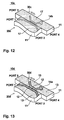
- FIG. 12 is a perspective view of the antenna device of the instant embodiment.
- the basic function of the antenna device of the instant embodiment is the same as that of the antenna device of the first embodiment, and its detailed description will be omitted.
- the antenna device 10c of the instant embodiment is composed of a directional coupler, and a primary radiator.
- the directional coupler comprises a first transmission line 20c which consists of a slot line formed by two conductors 17 arranged on one of the main faces of the dielectric substrate 11 through a gap between them, and a second transmission line 30c which consists of a slot line formed in a similar manner.
- the primary radiator consists of a slot antenna 14b connected to the second transmission line 30c.
- the first transmission line 20c and the second transmission line 30c have their transmission line portions which are linearly adjacent to each other. Through the portions, the two transmission lines are coupled to each other and function as a directional coupler.
- the first transmission line 20c is fixed, and a driving mechanism (not shown in FIG. 12) using a voice coil motor, a pulse motor, or the like is attached to the second transmission line 30c, and thereby, the second transmission line 30c can be shifted in the direction parallel to the line passing through the port 3 and the port 4 in FIG. 12.
- FIG. 13 is a perspective view of the antenna device of the instant embodiment.
- the basic function of the antenna device of the instant embodiment is the same as that of the antenna device of the first embodiment, and its detailed description will be omitted.
- the antenna device 10d of the instant embodiment is composed of a directional coupler and a primary radiator.
- the directional coupler comprises a first transmission line 20d which consists of a coplanar line composed of the line conductor 12 formed on one of the main-faces of the dielectric substrate 11 and the ground conductor 13 arranged through a space to the line conductor 12, and a second transmission line 30d which consists of a coplanar line formed in a similar manner.
- the primary radiator consists of a patch antenna 14a connected to the second transmission line 30d.
- the first transmission line 20d and the second transmission line 30d have their transmission line portions which are linearly adjacent to each other. Through the portions, the two transmission lines are coupled to each other and function as the directional coupler.
- the first transmission line 20d is fixed, and a driving mechanism (not shown in FIG. 13) using a voice coil motor, a pulse motor, or the like is attached to the second transmission line 30d, and thereby, the second transmission line 30d can be shifted in the direction parallel to the line passing through the port 3 and the port 4 in FIG. 13.
- FIG. 14 is a perspective view of the antenna device of the instant embodiment.
- the basic function of the antenna device of the instant embodiment is the same as that of the antenna device of the first embodiment, and its detailed description will be omitted.
- an antenna device 10e of the instant embodiment is composed of a directional coupler and a primary radiator.
- the directional coupler comprises a first transmission line 20e which consists of a guide wave, and a second transmission line 30e which consists of a guide wave as well.
- the primary radiator consists of a horn antenna 14c connected to the second transmission line 30e.
- the first transmission line 20e is fixed, and a driving mechanism (not shown in FIG. 14) using a voice coil motor, a pulse motor, or the like is attached to the second transmission line 30e, and thereby, the second transmission line 30e can be shifted in the direction parallel to the line passing through the port 3 and the port 4 in FIG. 14.
- the first transmission line 20e and the second transmission line 30e have their transmission line portions which are linearly adjacent to each other. Through the portions, the two transmission lines are coupled to each other and function as a directional coupler. More particularly, at the surfaces of the first transmission line 20e and the second transmission line 30e which are adjacent to each other, holes 18a and 18b for coupling are formed, respectively.
- the hole 18a of the first transmission line 20e has a larger size in the shifting direction than each of the holes 18b of the second transmission line 30e. Accordingly, the first transmission line 20e and the second transmission line 30e keep being coupled with each other when the second transmission line 30e is shifted, due to the holes 18a and 18b for coupling, and the horn antenna 14c can be shifted.
- the antenna device 10e having three holes 18b for coupling which are separated at a distance of ⁇ g/4 from each other is used. However, at least four holes for coupling may be formed.
- FIG. 15 is a perspective view of the antenna device of the instant embodiment.
- the basic function of the antenna device of the instant embodiment is the same as that of the antenna device of the first embodiment, and its detailed description will be omitted.
- an antenna device 10f of the instant embodiment is composed of a directional coupler and a primary radiator.
- the directional coupler comprises a first transmission line 20f which consists of a suspended line composed of a cylindrical ground conductor 13, the dielectric substrate 11 disposed in the center of the ground conductor 13, and the line conductor 12 formed on the dielectric substrate 11, and a second transmission line 30f which consists of a suspended line formed in a similar manner.
- the primary radiator consists of a slot antenna 14b connected to the second transmission line 30f.
- the first transmission line 20f is fixed, and a driving mechanism (not shown in FIG.
- the first transmission line 20f and the second transmission line 30f have their transmission line portions which are linearly adjacent to each other. Through the portions, the two transmission lines are coupled to each other and function as a directional coupler. More particularly, at the surfaces of the first transmission line 20f and the second transmission line 30f which are adjacent to each other, holes 18a and 18b for coupling are provided, respectively.
- the hole 18a of the first transmission line 20f has a larger size in the shifting direction than the hole 18b of the second transmission line 30f. Accordingly, the first transmission line 20f and the second transmission line 30f keep being coupled with each other when the second transmission line 30f is shifted, due to the holes 18a and 18b for coupling, and the slot antenna 14b can be shifted.
- the first transmission line and the second transmission line lines of the sane type, for example, the microstrip line and the microstrip line, are employed.
- the directional coupler may be formed of a combination of transmission lines of different types, for example, the microstrip line and the coplanar line or the like may be employed.
- FIG. 16 is a block diagram showing the configuration of the transmitting - receiving device of the present invention.
- a transmitting - receiving device 40 of the present invention comprises an antenna 10, a circulator 41 connected to the antenna device 10, an oscillator 42 connected to one of the ports of the circulator 41, a mixer 43 connected to the other port of the circulator 41, a second circulator 44 connected between the circulator 41 and the oscillator 42, and couplers 45 and 46.
- the oscillator 42 is a voltage-control oscillator.
- the oscillation frequency is changed by applying a voltage to its bias terminal.
- the antenna device 10 in FIG. 16 is the same as that shown in each of the first through sixth embodiments.
- a dielectric lens (not shown in FIG. 16) is arranged in the radiation direction of an electromagnetic wave from the primary antenna device.
- a signal from the oscillator 42 is propagated through the circulator 44, the coupler 45, and the circulator 41 to the primary radiator of the antenna device 10, and radiated through the dielectric lens.
- a part of the signal from the oscillator 42 as a local signal is supplied through the couplers 45 and 46 to the mixer 43.
- the reflected wave from an object is supplied through the antenna device 10, the circulator 41, and the coupler 46 to the mixer 43 as an RF signal.
- the mixer 43 as a balanced mixer outputs as an IF signal a differential component between the RF signal and the local signal.
- FIGS. 17 through 24 exemplified applications of the directional coupler in accordance with the present invention will be described with reference to FIGS. 17 through 24.
- the embodiment described below can be applied to all the described-above transmission lines. However, the description will be carried out in reference to the microstrip lines. Like parts of the first embodiment and the instant embodiment are designated by like reference numerals and signs, and their detailed description will be omitted.
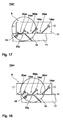
- FIGS. 17 through 20 are plan views of the antenna device of the instant embodiment, respectively.
- an antenna device 10a1 of the instant embodiment comprises a fixed first transmission line 20a, a shifting section A including three second transmission lines 30ax, 30ay, and 30az and three patch antennas 14ax, 14ay, and 14az connected to the second transmission lines 30ax, 30ay, and 30az, respectively, and a dielectric lens 16 fixed to the upper side of them. Further, a terminal resisting film 19 is formed on one end of the first transmission line 20a.
- the antenna device 10a1 having the above-described configuration, for example as shown in FIG. 17, when the first transmission line 20a and the second transmission line 30ax have their portions linearly adjacent to each other, both are coupled to each other, and an electromagnetic wave is radiated through the patch antenna 14ax.
- the shifting section A is shifted while the first transmission line 20a and the second transmission line 30ax are kept in the coupled state, and thereby, the position of the patch antenna 14ax is changed, so that the scanning of the radiation beam can be performed in the lower section.
- the shifting section A is further shifted, so that the first transmission line 20a and the second transmission line 30ay get to have their portions linearly adjacent to each other, as shown in FIG. 18, when both are coupled to each other, and an electromagnetic wave is radiated through the patch antenna 14ay. That is, the shifting section A is shifted while the coupling state is kept, and thereby, the position of the patch antenna 14ay is shifted, so that the scanning with the radiation beam can be carried out in the middle section.
- the shifting section A when the shifting section A is shifted to the position shown in FIG. 20, the first transmission line 20a is not coupled to any of the second transmission lines, and no beam is radiated through the antenna device 10a1.
- the directional coupler having one first transmission line and one second transmission line
- the second transmission line is shifted, and thereby, the coupling state in which the first and second transmission lines have the linearly-adjacent portions is changed to the non-coupling state where the linearly-adjacent portions are absent.
- a signal sent from the first transmission line can be switched to "be transmitted" or "not to be transmitted” to the second transmission line.
- the directional coupler can be used as a switch.
- FIG. 21 is a plan view of the antenna device of the instant embodiment.
- FIGS. 22 through 24 are side views showing the concept of the beam scanning, respectively.
- an antenna device 10a2 of the instant embodiment comprises a fixed section B having three first transmission lines 20ax, 20ay, and 20az, a shifting section A having the three second transmission lines 30ax, 30ay, and 30az to be coupled to the first transmission lines 20ax, 20ay, and 20az, the three patch antennas 14ax, 14ay, and 14az connected to the second transmission lines 30ax, 30ay, and 30az, respectively, and three dielectric lenses 16a, 16b, and 16c fixed to the upper side of them.
- An electromagnetic wave is sent through the patch antenna 14ax, which is one of the three patch antennas 14ax, 14ay, and 14az, and an electromagnetic wave is received through the other two patch antennas 14ax and 14ay.
- an appropriate transmitting or receiving circuit not shown in FIG. 21, is connected, and thereby, a transmitting - receiving device is formed.
- Terminal resisting films 19 are formed on one ends of the first transmission lines 20ax, 20ay, and 20az, respectively.
- the shifting section A is shifted by use of a driving means not shown in FIG. 21, and thereby, the three patch antennas 14ax, 14ay, and 14az are simultaneously shifted.
- an angel can be measured in a wide range at a desired detection distance with an appropriate measuring-angle resolution power.
- the positions of the patch antennas 14ax, 14ay, and 14az, and the dielectric lenses 16a, 16b, and 16c are so defined that a wave-sending beam is directed at 0° to the forward direction, one of the receiving beams to the right by 15° to the forward direction, and the other receiving beam to the left by 15° to the forward direction.
- the angle measurement can be carried out in the range between the two receiving beams. If the angle-measuring range is desired to be widened, provided that the defined positions of the patch antennas are fixed, a method for widening the ranges of the respective beams themselves and a method for widening the distance between the two beams may be proposed. However, there is the problem that by the former method, the detection distance becomes short, while by the later method, the angle-measurement resolution power is reduced.
- the shifting section A in which the three patch antennas 14ax, 14ay, and 14az are formed is shifted, so that for example, as shown in FIG. 23, the wave-sending beam is directed to the left by 15° to the forward direction, one of the receiving beams at 0° to the forward direction, and the other receiving beam to the left by 30° to the forward direction.
- the shifting section A is shifted in the opposite direction, so that the wave-sending beam is directed to the right by 15° to the forward direction, one of the receiving beam to the right by 30° to the forward direction, and the other receiving beam at 0° to the front direction.
- the shifting section A is so shifted that the beam scans, and thereby, the angle-measurement can be performed in a wide range without the detection distance shortened or the angle-measurement resolution power reduced.
- the relative position of the two transmission lines is changed while the coupling is kept. Accordingly, when the primary radiator is connected to one of the transmission lines, the position of the primary radiator can be shifted while the electromagnetic wave is being radiated. That is, by shifting the transmission line which is relatively light in weight, the radiation beam from the antenna can be caused to scan. Thus, it is unnecessary to provide a large-sized driving means for moving the whole of the casing containing the transmitting - receiving device, and the antenna device can be miniaturized.
Landscapes
- Variable-Direction Aerials And Aerial Arrays (AREA)
- Radar Systems Or Details Thereof (AREA)
- Waveguides (AREA)
- Aerials With Secondary Devices (AREA)
- Waveguide Aerials (AREA)
Claims (4)
- Eine Antennenvorrichtung (10a; 10b; 10c; 10d; 10e; 10f) mit folgenden Merkmalen:einem Richtkoppler, der eine erste feste Übertragungsleitung (20a; 20a1; 20b; 20b5; 20c; 20d; 20e) und eine zweite verschiebbare Übertragungsleitung (30a; 30a1; 30b; 30b5; 30c; 30d; 30e) aufweist, wobei die erste und die zweite Übertragungsleitung sich linear erstreckende benachbarte Abschnitte aufweisen, wobei die relativen Positionen der ersten Übertragungsleitung (20a; 20a1; 20b; 20b5; 20c; 20d; 20e) und der zweiten Übertragungsleitung (30a; 30a1; 30b; 30b5; 30c; 30d; 30e) veränderbar sind;dadurch gekennzeichnet, dass die Antennenvorrichtung ferner eine dielektrische Linse (16) und einen Primärstrahler (14a; 14b; 14c; 15), der in der Brennebene der dielektrischen Linse positioniert ist und mit der zweiten Übertragungsleitung gekoppelt ist, aufweist, wobei die relativen Positionen des Primärstrahlers (14a; 14b; 14c; 15) und der ersten Übertragungsleitung (20a; 20a1; 20b; 20b5; 20c; 20d; 20e) in der Richtung der Längenerstreckung der benachbarten Abschnitte der ersten und der zweiten Übertragungsleitung verschiebbar sind, zum Variieren der Position des Primärstrahlers in der Brennebene der dielektrischen Linse (16), um dadurch die Richtwirkung der Strahlung zu verändern;
wobei die erste und die zweite Übertragungsleitung Streifenleitungen oder koplanare Leitungen sind und die Antenne eine Patch-Antenne ist, oder
wobei die erste und die zweite Übertragungsleitung Schlitzleitungen oder Schwebeleitungen sind und die Antenne eine Schlitzantenne ist. - Eine Antennenvorrichtung (10a; 10b; 10c; 10d; 10e; 10f) mit folgenden Merkmalen:einem Richtkoppler, der eine erste feste Übertragungsleitung (20a; 20a1; 20b; 20b5; 20c; 20d; 20e) und eine zweite verschiebbare Übertragungsleitung (30a; 30a1; 30b; 30b5; 30c; 30d; 30e) aufweist, wobei die erste und die zweite Übertragungsleitung sich linear erstreckende benachbarte Abschnitte aufweisen, wobei die relativen Positionen der ersten Übertragungsleitung (20a; 20a1; 20b; 20b5; 20c; 20d; 20e) und der zweiten Übertragungsleitung (30a; 30a1; 30b; 30b5; 30c; 30d; 30e) veränderbar sind;dadurch gekennzeichnet, dass die Antennenvorrichtung ferner eine dielektrische Linse (16) und einen Primärstrahler (14a; 14b; 14c; 15), der in der Brennebene der dielektrischen Linse positioniert und mit der zweiten Übertragungsleitung gekoppelt ist, aufweist, wobei die relativen Positionen des Primärstrahlers (14a; 14b; 14c; 15) und der ersten Übertragungsleitung (20a; 20a1; 20b; 20b5; 20c; 20d; 20e) in der Richtung der Längenerstreckung der benachbarten Abschnitte der ersten und der zweiten Übertragungsleitung verschiebbar sind, zum Variieren der Position des Primärstrahlers in der Brennebene der dielektrischen Linse (16), um dadurch die Richtwirkung der Strahlung zu verändern;
wobei die zweite Übertragungsleitung ein Wellenleiter ist und der Primärstrahler eine Hornantenne ist. - Eine Antennenvorrichtung (10a; 10b; 10c; 10d; 10e; 10f) gemäß Anspruch 1 oder 2, die ferner einen Treibermechanismus zum Treiben des Richtkopplers und des Primärstrahlers (14a; 14b; 14c; 15) aufweist.
- Eine Sende-/Empfangsvorrichtung (40), die die Antennenvorrichtung gemäß einem der Ansprüche 1 bis 3 und eine Sende-/Empfangsvorrichtung, die mit der Antennenvorrichtung verbunden ist, umfasst.
Applications Claiming Priority (4)
| Application Number | Priority Date | Filing Date | Title |
|---|---|---|---|
| JP19169298 | 1998-07-07 | ||
| JP19169298 | 1998-07-07 | ||
| JP16010099A JP3617374B2 (ja) | 1998-07-07 | 1999-06-07 | 方向性結合器、アンテナ装置および送受信装置 |
| JP16010099 | 1999-06-07 |
Publications (3)
| Publication Number | Publication Date |
|---|---|
| EP0973226A2 EP0973226A2 (de) | 2000-01-19 |
| EP0973226A3 EP0973226A3 (de) | 2002-04-24 |
| EP0973226B1 true EP0973226B1 (de) | 2006-06-14 |
Family
ID=26486693
Family Applications (1)
| Application Number | Title | Priority Date | Filing Date |
|---|---|---|---|
| EP99113099A Expired - Lifetime EP0973226B1 (de) | 1998-07-07 | 1999-07-06 | Richtkoppler, Antennenanordnung, und Übertragungs-Empfangsanordnung |
Country Status (5)
| Country | Link |
|---|---|
| US (1) | US6433741B2 (de) |
| EP (1) | EP0973226B1 (de) |
| JP (1) | JP3617374B2 (de) |
| CA (1) | CA2276979C (de) |
| DE (1) | DE69931850T2 (de) |
Cited By (2)
| Publication number | Priority date | Publication date | Assignee | Title |
|---|---|---|---|---|
| DE102007031841A1 (de) * | 2007-07-08 | 2009-01-15 | Imst Gmbh | Breitseiten-gekoppelte ultra-kompakte Multi-Band Kopplerstrukturen in Spalt-geführter Oberflächen Plasmon Polariton Wellenleitertechnik |
| CN119181950A (zh) * | 2024-11-26 | 2024-12-24 | 四川天邑康和通信股份有限公司 | 一种小型化一体式结构耦合器 |
Families Citing this family (170)
| Publication number | Priority date | Publication date | Assignee | Title |
|---|---|---|---|---|
| JP3287309B2 (ja) * | 1998-07-06 | 2002-06-04 | 株式会社村田製作所 | 方向性結合器、アンテナ装置及び送受信装置 |
| KR100364696B1 (ko) * | 1999-10-28 | 2003-01-24 | 엘지전자 주식회사 | 플라즈마 디스플레이 패널의 구조와 그 구동방법 |
| JP3735510B2 (ja) * | 2000-04-18 | 2006-01-18 | 株式会社村田製作所 | 伝送線路接続構造、高周波モジュールおよび通信装置 |
| US6731244B2 (en) * | 2002-06-27 | 2004-05-04 | Harris Corporation | High efficiency directional coupler |
| JP3841291B2 (ja) * | 2002-11-19 | 2006-11-01 | ソニー・エリクソン・モバイルコミュニケーションズ株式会社 | 携帯無線装置 |
| DE10261027A1 (de) * | 2002-12-24 | 2004-07-08 | Robert Bosch Gmbh | Winkelauflösendes Antennensystem |
| JP4908596B2 (ja) * | 2007-12-21 | 2012-04-04 | ビ−エイイ− システムズ パブリック リミテッド カンパニ− | マイクロ波結合器 |
| US9113347B2 (en) | 2012-12-05 | 2015-08-18 | At&T Intellectual Property I, Lp | Backhaul link for distributed antenna system |
| US10009065B2 (en) | 2012-12-05 | 2018-06-26 | At&T Intellectual Property I, L.P. | Backhaul link for distributed antenna system |
| US9525524B2 (en) | 2013-05-31 | 2016-12-20 | At&T Intellectual Property I, L.P. | Remote distributed antenna system |
| US9999038B2 (en) | 2013-05-31 | 2018-06-12 | At&T Intellectual Property I, L.P. | Remote distributed antenna system |
| US8897697B1 (en) | 2013-11-06 | 2014-11-25 | At&T Intellectual Property I, Lp | Millimeter-wave surface-wave communications |
| US9209902B2 (en) | 2013-12-10 | 2015-12-08 | At&T Intellectual Property I, L.P. | Quasi-optical coupler |
| US9406990B2 (en) * | 2014-01-20 | 2016-08-02 | Keyssa, Inc. | Adjustable waveguide assembly |
| KR101811245B1 (ko) * | 2014-08-11 | 2017-12-22 | 한밭대학교 산학협력단 | 가변 커플러 및 스트립라인 가변커플러 |
| US9692101B2 (en) | 2014-08-26 | 2017-06-27 | At&T Intellectual Property I, L.P. | Guided wave couplers for coupling electromagnetic waves between a waveguide surface and a surface of a wire |
| US9768833B2 (en) | 2014-09-15 | 2017-09-19 | At&T Intellectual Property I, L.P. | Method and apparatus for sensing a condition in a transmission medium of electromagnetic waves |
| US10063280B2 (en) * | 2014-09-17 | 2018-08-28 | At&T Intellectual Property I, L.P. | Monitoring and mitigating conditions in a communication network |
| US9628854B2 (en) * | 2014-09-29 | 2017-04-18 | At&T Intellectual Property I, L.P. | Method and apparatus for distributing content in a communication network |
| US9615269B2 (en) | 2014-10-02 | 2017-04-04 | At&T Intellectual Property I, L.P. | Method and apparatus that provides fault tolerance in a communication network |
| US9685992B2 (en) | 2014-10-03 | 2017-06-20 | At&T Intellectual Property I, L.P. | Circuit panel network and methods thereof |
| US9503189B2 (en) | 2014-10-10 | 2016-11-22 | At&T Intellectual Property I, L.P. | Method and apparatus for arranging communication sessions in a communication system |
| US9762289B2 (en) | 2014-10-14 | 2017-09-12 | At&T Intellectual Property I, L.P. | Method and apparatus for transmitting or receiving signals in a transportation system |
| US9973299B2 (en) | 2014-10-14 | 2018-05-15 | At&T Intellectual Property I, L.P. | Method and apparatus for adjusting a mode of communication in a communication network |
| US9653770B2 (en) | 2014-10-21 | 2017-05-16 | At&T Intellectual Property I, L.P. | Guided wave coupler, coupling module and methods for use therewith |
| US9780834B2 (en) * | 2014-10-21 | 2017-10-03 | At&T Intellectual Property I, L.P. | Method and apparatus for transmitting electromagnetic waves |
| US9769020B2 (en) | 2014-10-21 | 2017-09-19 | At&T Intellectual Property I, L.P. | Method and apparatus for responding to events affecting communications in a communication network |
| US9520945B2 (en) | 2014-10-21 | 2016-12-13 | At&T Intellectual Property I, L.P. | Apparatus for providing communication services and methods thereof |
| US9577306B2 (en) | 2014-10-21 | 2017-02-21 | At&T Intellectual Property I, L.P. | Guided-wave transmission device and methods for use therewith |
| US9627768B2 (en) | 2014-10-21 | 2017-04-18 | At&T Intellectual Property I, L.P. | Guided-wave transmission device with non-fundamental mode propagation and methods for use therewith |
| US9564947B2 (en) | 2014-10-21 | 2017-02-07 | At&T Intellectual Property I, L.P. | Guided-wave transmission device with diversity and methods for use therewith |
| US9312919B1 (en) | 2014-10-21 | 2016-04-12 | At&T Intellectual Property I, Lp | Transmission device with impairment compensation and methods for use therewith |
| US9800327B2 (en) | 2014-11-20 | 2017-10-24 | At&T Intellectual Property I, L.P. | Apparatus for controlling operations of a communication device and methods thereof |
| US9544006B2 (en) | 2014-11-20 | 2017-01-10 | At&T Intellectual Property I, L.P. | Transmission device with mode division multiplexing and methods for use therewith |
| US9954287B2 (en) | 2014-11-20 | 2018-04-24 | At&T Intellectual Property I, L.P. | Apparatus for converting wireless signals and electromagnetic waves and methods thereof |
| US9654173B2 (en) | 2014-11-20 | 2017-05-16 | At&T Intellectual Property I, L.P. | Apparatus for powering a communication device and methods thereof |
| US10009067B2 (en) | 2014-12-04 | 2018-06-26 | At&T Intellectual Property I, L.P. | Method and apparatus for configuring a communication interface |
| US10340573B2 (en) | 2016-10-26 | 2019-07-02 | At&T Intellectual Property I, L.P. | Launcher with cylindrical coupling device and methods for use therewith |
| US9742462B2 (en) | 2014-12-04 | 2017-08-22 | At&T Intellectual Property I, L.P. | Transmission medium and communication interfaces and methods for use therewith |
| US9461706B1 (en) | 2015-07-31 | 2016-10-04 | At&T Intellectual Property I, Lp | Method and apparatus for exchanging communication signals |
| US9997819B2 (en) | 2015-06-09 | 2018-06-12 | At&T Intellectual Property I, L.P. | Transmission medium and method for facilitating propagation of electromagnetic waves via a core |
| US10243784B2 (en) | 2014-11-20 | 2019-03-26 | At&T Intellectual Property I, L.P. | System for generating topology information and methods thereof |
| US9680670B2 (en) | 2014-11-20 | 2017-06-13 | At&T Intellectual Property I, L.P. | Transmission device with channel equalization and control and methods for use therewith |
| US10144036B2 (en) | 2015-01-30 | 2018-12-04 | At&T Intellectual Property I, L.P. | Method and apparatus for mitigating interference affecting a propagation of electromagnetic waves guided by a transmission medium |
| US9876570B2 (en) | 2015-02-20 | 2018-01-23 | At&T Intellectual Property I, Lp | Guided-wave transmission device with non-fundamental mode propagation and methods for use therewith |
| US9749013B2 (en) | 2015-03-17 | 2017-08-29 | At&T Intellectual Property I, L.P. | Method and apparatus for reducing attenuation of electromagnetic waves guided by a transmission medium |
| US10224981B2 (en) | 2015-04-24 | 2019-03-05 | At&T Intellectual Property I, Lp | Passive electrical coupling device and methods for use therewith |
| US9705561B2 (en) | 2015-04-24 | 2017-07-11 | At&T Intellectual Property I, L.P. | Directional coupling device and methods for use therewith |
| US9948354B2 (en) | 2015-04-28 | 2018-04-17 | At&T Intellectual Property I, L.P. | Magnetic coupling device with reflective plate and methods for use therewith |
| US9793954B2 (en) | 2015-04-28 | 2017-10-17 | At&T Intellectual Property I, L.P. | Magnetic coupling device and methods for use therewith |
| US9748626B2 (en) | 2015-05-14 | 2017-08-29 | At&T Intellectual Property I, L.P. | Plurality of cables having different cross-sectional shapes which are bundled together to form a transmission medium |
| US9871282B2 (en) | 2015-05-14 | 2018-01-16 | At&T Intellectual Property I, L.P. | At least one transmission medium having a dielectric surface that is covered at least in part by a second dielectric |
| US9490869B1 (en) | 2015-05-14 | 2016-11-08 | At&T Intellectual Property I, L.P. | Transmission medium having multiple cores and methods for use therewith |
| US10650940B2 (en) | 2015-05-15 | 2020-05-12 | At&T Intellectual Property I, L.P. | Transmission medium having a conductive material and methods for use therewith |
| US10679767B2 (en) | 2015-05-15 | 2020-06-09 | At&T Intellectual Property I, L.P. | Transmission medium having a conductive material and methods for use therewith |
| US9917341B2 (en) | 2015-05-27 | 2018-03-13 | At&T Intellectual Property I, L.P. | Apparatus and method for launching electromagnetic waves and for modifying radial dimensions of the propagating electromagnetic waves |
| US10812174B2 (en) | 2015-06-03 | 2020-10-20 | At&T Intellectual Property I, L.P. | Client node device and methods for use therewith |
| US10348391B2 (en) | 2015-06-03 | 2019-07-09 | At&T Intellectual Property I, L.P. | Client node device with frequency conversion and methods for use therewith |
| US9912381B2 (en) | 2015-06-03 | 2018-03-06 | At&T Intellectual Property I, Lp | Network termination and methods for use therewith |
| US10103801B2 (en) | 2015-06-03 | 2018-10-16 | At&T Intellectual Property I, L.P. | Host node device and methods for use therewith |
| US10154493B2 (en) | 2015-06-03 | 2018-12-11 | At&T Intellectual Property I, L.P. | Network termination and methods for use therewith |
| US9866309B2 (en) | 2015-06-03 | 2018-01-09 | At&T Intellectual Property I, Lp | Host node device and methods for use therewith |
| US9913139B2 (en) | 2015-06-09 | 2018-03-06 | At&T Intellectual Property I, L.P. | Signal fingerprinting for authentication of communicating devices |
| US9608692B2 (en) | 2015-06-11 | 2017-03-28 | At&T Intellectual Property I, L.P. | Repeater and methods for use therewith |
| US10142086B2 (en) | 2015-06-11 | 2018-11-27 | At&T Intellectual Property I, L.P. | Repeater and methods for use therewith |
| US9820146B2 (en) | 2015-06-12 | 2017-11-14 | At&T Intellectual Property I, L.P. | Method and apparatus for authentication and identity management of communicating devices |
| US9667317B2 (en) | 2015-06-15 | 2017-05-30 | At&T Intellectual Property I, L.P. | Method and apparatus for providing security using network traffic adjustments |
| US9509415B1 (en) | 2015-06-25 | 2016-11-29 | At&T Intellectual Property I, L.P. | Methods and apparatus for inducing a fundamental wave mode on a transmission medium |
| US9640850B2 (en) | 2015-06-25 | 2017-05-02 | At&T Intellectual Property I, L.P. | Methods and apparatus for inducing a non-fundamental wave mode on a transmission medium |
| US9865911B2 (en) | 2015-06-25 | 2018-01-09 | At&T Intellectual Property I, L.P. | Waveguide system for slot radiating first electromagnetic waves that are combined into a non-fundamental wave mode second electromagnetic wave on a transmission medium |
| US9836957B2 (en) | 2015-07-14 | 2017-12-05 | At&T Intellectual Property I, L.P. | Method and apparatus for communicating with premises equipment |
| US9628116B2 (en) | 2015-07-14 | 2017-04-18 | At&T Intellectual Property I, L.P. | Apparatus and methods for transmitting wireless signals |
| US9847566B2 (en) | 2015-07-14 | 2017-12-19 | At&T Intellectual Property I, L.P. | Method and apparatus for adjusting a field of a signal to mitigate interference |
| US10044409B2 (en) | 2015-07-14 | 2018-08-07 | At&T Intellectual Property I, L.P. | Transmission medium and methods for use therewith |
| US10320586B2 (en) | 2015-07-14 | 2019-06-11 | At&T Intellectual Property I, L.P. | Apparatus and methods for generating non-interfering electromagnetic waves on an insulated transmission medium |
| US10148016B2 (en) | 2015-07-14 | 2018-12-04 | At&T Intellectual Property I, L.P. | Apparatus and methods for communicating utilizing an antenna array |
| US10033108B2 (en) | 2015-07-14 | 2018-07-24 | At&T Intellectual Property I, L.P. | Apparatus and methods for generating an electromagnetic wave having a wave mode that mitigates interference |
| US10033107B2 (en) | 2015-07-14 | 2018-07-24 | At&T Intellectual Property I, L.P. | Method and apparatus for coupling an antenna to a device |
| US9853342B2 (en) | 2015-07-14 | 2017-12-26 | At&T Intellectual Property I, L.P. | Dielectric transmission medium connector and methods for use therewith |
| US9722318B2 (en) | 2015-07-14 | 2017-08-01 | At&T Intellectual Property I, L.P. | Method and apparatus for coupling an antenna to a device |
| US10205655B2 (en) | 2015-07-14 | 2019-02-12 | At&T Intellectual Property I, L.P. | Apparatus and methods for communicating utilizing an antenna array and multiple communication paths |
| US9882257B2 (en) | 2015-07-14 | 2018-01-30 | At&T Intellectual Property I, L.P. | Method and apparatus for launching a wave mode that mitigates interference |
| US10170840B2 (en) | 2015-07-14 | 2019-01-01 | At&T Intellectual Property I, L.P. | Apparatus and methods for sending or receiving electromagnetic signals |
| US10341142B2 (en) | 2015-07-14 | 2019-07-02 | At&T Intellectual Property I, L.P. | Apparatus and methods for generating non-interfering electromagnetic waves on an uninsulated conductor |
| US9608740B2 (en) | 2015-07-15 | 2017-03-28 | At&T Intellectual Property I, L.P. | Method and apparatus for launching a wave mode that mitigates interference |
| US9793951B2 (en) | 2015-07-15 | 2017-10-17 | At&T Intellectual Property I, L.P. | Method and apparatus for launching a wave mode that mitigates interference |
| US10090606B2 (en) | 2015-07-15 | 2018-10-02 | At&T Intellectual Property I, L.P. | Antenna system with dielectric array and methods for use therewith |
| US9948333B2 (en) | 2015-07-23 | 2018-04-17 | At&T Intellectual Property I, L.P. | Method and apparatus for wireless communications to mitigate interference |
| US9749053B2 (en) | 2015-07-23 | 2017-08-29 | At&T Intellectual Property I, L.P. | Node device, repeater and methods for use therewith |
| US10784670B2 (en) | 2015-07-23 | 2020-09-22 | At&T Intellectual Property I, L.P. | Antenna support for aligning an antenna |
| US9912027B2 (en) | 2015-07-23 | 2018-03-06 | At&T Intellectual Property I, L.P. | Method and apparatus for exchanging communication signals |
| US9871283B2 (en) | 2015-07-23 | 2018-01-16 | At&T Intellectual Property I, Lp | Transmission medium having a dielectric core comprised of plural members connected by a ball and socket configuration |
| US9735833B2 (en) | 2015-07-31 | 2017-08-15 | At&T Intellectual Property I, L.P. | Method and apparatus for communications management in a neighborhood network |
| US10020587B2 (en) | 2015-07-31 | 2018-07-10 | At&T Intellectual Property I, L.P. | Radial antenna and methods for use therewith |
| US9967173B2 (en) | 2015-07-31 | 2018-05-08 | At&T Intellectual Property I, L.P. | Method and apparatus for authentication and identity management of communicating devices |
| US9904535B2 (en) | 2015-09-14 | 2018-02-27 | At&T Intellectual Property I, L.P. | Method and apparatus for distributing software |
| US10136434B2 (en) | 2015-09-16 | 2018-11-20 | At&T Intellectual Property I, L.P. | Method and apparatus for use with a radio distributed antenna system having an ultra-wideband control channel |
| US10051629B2 (en) | 2015-09-16 | 2018-08-14 | At&T Intellectual Property I, L.P. | Method and apparatus for use with a radio distributed antenna system having an in-band reference signal |
| US9705571B2 (en) | 2015-09-16 | 2017-07-11 | At&T Intellectual Property I, L.P. | Method and apparatus for use with a radio distributed antenna system |
| US10009063B2 (en) | 2015-09-16 | 2018-06-26 | At&T Intellectual Property I, L.P. | Method and apparatus for use with a radio distributed antenna system having an out-of-band reference signal |
| US10079661B2 (en) | 2015-09-16 | 2018-09-18 | At&T Intellectual Property I, L.P. | Method and apparatus for use with a radio distributed antenna system having a clock reference |
| US10009901B2 (en) | 2015-09-16 | 2018-06-26 | At&T Intellectual Property I, L.P. | Method, apparatus, and computer-readable storage medium for managing utilization of wireless resources between base stations |
| US9769128B2 (en) | 2015-09-28 | 2017-09-19 | At&T Intellectual Property I, L.P. | Method and apparatus for encryption of communications over a network |
| US9729197B2 (en) | 2015-10-01 | 2017-08-08 | At&T Intellectual Property I, L.P. | Method and apparatus for communicating network management traffic over a network |
| US9882277B2 (en) | 2015-10-02 | 2018-01-30 | At&T Intellectual Property I, Lp | Communication device and antenna assembly with actuated gimbal mount |
| US9876264B2 (en) | 2015-10-02 | 2018-01-23 | At&T Intellectual Property I, Lp | Communication system, guided wave switch and methods for use therewith |
| US10074890B2 (en) | 2015-10-02 | 2018-09-11 | At&T Intellectual Property I, L.P. | Communication device and antenna with integrated light assembly |
| US10355367B2 (en) | 2015-10-16 | 2019-07-16 | At&T Intellectual Property I, L.P. | Antenna structure for exchanging wireless signals |
| US10051483B2 (en) | 2015-10-16 | 2018-08-14 | At&T Intellectual Property I, L.P. | Method and apparatus for directing wireless signals |
| US10665942B2 (en) | 2015-10-16 | 2020-05-26 | At&T Intellectual Property I, L.P. | Method and apparatus for adjusting wireless communications |
| US9912419B1 (en) | 2016-08-24 | 2018-03-06 | At&T Intellectual Property I, L.P. | Method and apparatus for managing a fault in a distributed antenna system |
| US9860075B1 (en) | 2016-08-26 | 2018-01-02 | At&T Intellectual Property I, L.P. | Method and communication node for broadband distribution |
| US10291311B2 (en) | 2016-09-09 | 2019-05-14 | At&T Intellectual Property I, L.P. | Method and apparatus for mitigating a fault in a distributed antenna system |
| US11032819B2 (en) | 2016-09-15 | 2021-06-08 | At&T Intellectual Property I, L.P. | Method and apparatus for use with a radio distributed antenna system having a control channel reference signal |
| US10135147B2 (en) | 2016-10-18 | 2018-11-20 | At&T Intellectual Property I, L.P. | Apparatus and methods for launching guided waves via an antenna |
| US10340600B2 (en) | 2016-10-18 | 2019-07-02 | At&T Intellectual Property I, L.P. | Apparatus and methods for launching guided waves via plural waveguide systems |
| US10135146B2 (en) | 2016-10-18 | 2018-11-20 | At&T Intellectual Property I, L.P. | Apparatus and methods for launching guided waves via circuits |
| US9876605B1 (en) | 2016-10-21 | 2018-01-23 | At&T Intellectual Property I, L.P. | Launcher and coupling system to support desired guided wave mode |
| US9991580B2 (en) | 2016-10-21 | 2018-06-05 | At&T Intellectual Property I, L.P. | Launcher and coupling system for guided wave mode cancellation |
| US10374316B2 (en) | 2016-10-21 | 2019-08-06 | At&T Intellectual Property I, L.P. | System and dielectric antenna with non-uniform dielectric |
| US10811767B2 (en) | 2016-10-21 | 2020-10-20 | At&T Intellectual Property I, L.P. | System and dielectric antenna with convex dielectric radome |
| US10312567B2 (en) * | 2016-10-26 | 2019-06-04 | At&T Intellectual Property I, L.P. | Launcher with planar strip antenna and methods for use therewith |
| US10224634B2 (en) | 2016-11-03 | 2019-03-05 | At&T Intellectual Property I, L.P. | Methods and apparatus for adjusting an operational characteristic of an antenna |
| US10291334B2 (en) | 2016-11-03 | 2019-05-14 | At&T Intellectual Property I, L.P. | System for detecting a fault in a communication system |
| US10225025B2 (en) | 2016-11-03 | 2019-03-05 | At&T Intellectual Property I, L.P. | Method and apparatus for detecting a fault in a communication system |
| US10498044B2 (en) | 2016-11-03 | 2019-12-03 | At&T Intellectual Property I, L.P. | Apparatus for configuring a surface of an antenna |
| US10090594B2 (en) | 2016-11-23 | 2018-10-02 | At&T Intellectual Property I, L.P. | Antenna system having structural configurations for assembly |
| US10178445B2 (en) | 2016-11-23 | 2019-01-08 | At&T Intellectual Property I, L.P. | Methods, devices, and systems for load balancing between a plurality of waveguides |
| US10535928B2 (en) | 2016-11-23 | 2020-01-14 | At&T Intellectual Property I, L.P. | Antenna system and methods for use therewith |
| US10340603B2 (en) | 2016-11-23 | 2019-07-02 | At&T Intellectual Property I, L.P. | Antenna system having shielded structural configurations for assembly |
| US10340601B2 (en) | 2016-11-23 | 2019-07-02 | At&T Intellectual Property I, L.P. | Multi-antenna system and methods for use therewith |
| US10361489B2 (en) | 2016-12-01 | 2019-07-23 | At&T Intellectual Property I, L.P. | Dielectric dish antenna system and methods for use therewith |
| US10305190B2 (en) | 2016-12-01 | 2019-05-28 | At&T Intellectual Property I, L.P. | Reflecting dielectric antenna system and methods for use therewith |
| US10382976B2 (en) | 2016-12-06 | 2019-08-13 | At&T Intellectual Property I, L.P. | Method and apparatus for managing wireless communications based on communication paths and network device positions |
| US10694379B2 (en) | 2016-12-06 | 2020-06-23 | At&T Intellectual Property I, L.P. | Waveguide system with device-based authentication and methods for use therewith |
| US10135145B2 (en) | 2016-12-06 | 2018-11-20 | At&T Intellectual Property I, L.P. | Apparatus and methods for generating an electromagnetic wave along a transmission medium |
| US10326494B2 (en) | 2016-12-06 | 2019-06-18 | At&T Intellectual Property I, L.P. | Apparatus for measurement de-embedding and methods for use therewith |
| US10637149B2 (en) | 2016-12-06 | 2020-04-28 | At&T Intellectual Property I, L.P. | Injection molded dielectric antenna and methods for use therewith |
| US10819035B2 (en) | 2016-12-06 | 2020-10-27 | At&T Intellectual Property I, L.P. | Launcher with helical antenna and methods for use therewith |
| US10755542B2 (en) | 2016-12-06 | 2020-08-25 | At&T Intellectual Property I, L.P. | Method and apparatus for surveillance via guided wave communication |
| US10020844B2 (en) | 2016-12-06 | 2018-07-10 | T&T Intellectual Property I, L.P. | Method and apparatus for broadcast communication via guided waves |
| US10439675B2 (en) | 2016-12-06 | 2019-10-08 | At&T Intellectual Property I, L.P. | Method and apparatus for repeating guided wave communication signals |
| US9927517B1 (en) | 2016-12-06 | 2018-03-27 | At&T Intellectual Property I, L.P. | Apparatus and methods for sensing rainfall |
| US10727599B2 (en) | 2016-12-06 | 2020-07-28 | At&T Intellectual Property I, L.P. | Launcher with slot antenna and methods for use therewith |
| US10139820B2 (en) | 2016-12-07 | 2018-11-27 | At&T Intellectual Property I, L.P. | Method and apparatus for deploying equipment of a communication system |
| US10547348B2 (en) | 2016-12-07 | 2020-01-28 | At&T Intellectual Property I, L.P. | Method and apparatus for switching transmission mediums in a communication system |
| US9893795B1 (en) | 2016-12-07 | 2018-02-13 | At&T Intellectual Property I, Lp | Method and repeater for broadband distribution |
| US10027397B2 (en) | 2016-12-07 | 2018-07-17 | At&T Intellectual Property I, L.P. | Distributed antenna system and methods for use therewith |
| US10168695B2 (en) | 2016-12-07 | 2019-01-01 | At&T Intellectual Property I, L.P. | Method and apparatus for controlling an unmanned aircraft |
| US10243270B2 (en) | 2016-12-07 | 2019-03-26 | At&T Intellectual Property I, L.P. | Beam adaptive multi-feed dielectric antenna system and methods for use therewith |
| US10389029B2 (en) | 2016-12-07 | 2019-08-20 | At&T Intellectual Property I, L.P. | Multi-feed dielectric antenna system with core selection and methods for use therewith |
| US10359749B2 (en) | 2016-12-07 | 2019-07-23 | At&T Intellectual Property I, L.P. | Method and apparatus for utilities management via guided wave communication |
| US10446936B2 (en) | 2016-12-07 | 2019-10-15 | At&T Intellectual Property I, L.P. | Multi-feed dielectric antenna system and methods for use therewith |
| US10326689B2 (en) | 2016-12-08 | 2019-06-18 | At&T Intellectual Property I, L.P. | Method and system for providing alternative communication paths |
| US10389037B2 (en) | 2016-12-08 | 2019-08-20 | At&T Intellectual Property I, L.P. | Apparatus and methods for selecting sections of an antenna array and use therewith |
| US10069535B2 (en) | 2016-12-08 | 2018-09-04 | At&T Intellectual Property I, L.P. | Apparatus and methods for launching electromagnetic waves having a certain electric field structure |
| US10530505B2 (en) | 2016-12-08 | 2020-01-07 | At&T Intellectual Property I, L.P. | Apparatus and methods for launching electromagnetic waves along a transmission medium |
| US10411356B2 (en) | 2016-12-08 | 2019-09-10 | At&T Intellectual Property I, L.P. | Apparatus and methods for selectively targeting communication devices with an antenna array |
| US10916969B2 (en) | 2016-12-08 | 2021-02-09 | At&T Intellectual Property I, L.P. | Method and apparatus for providing power using an inductive coupling |
| US9911020B1 (en) | 2016-12-08 | 2018-03-06 | At&T Intellectual Property I, L.P. | Method and apparatus for tracking via a radio frequency identification device |
| US9998870B1 (en) | 2016-12-08 | 2018-06-12 | At&T Intellectual Property I, L.P. | Method and apparatus for proximity sensing |
| US10601494B2 (en) | 2016-12-08 | 2020-03-24 | At&T Intellectual Property I, L.P. | Dual-band communication device and method for use therewith |
| US10103422B2 (en) | 2016-12-08 | 2018-10-16 | At&T Intellectual Property I, L.P. | Method and apparatus for mounting network devices |
| US10777873B2 (en) | 2016-12-08 | 2020-09-15 | At&T Intellectual Property I, L.P. | Method and apparatus for mounting network devices |
| US10938108B2 (en) | 2016-12-08 | 2021-03-02 | At&T Intellectual Property I, L.P. | Frequency selective multi-feed dielectric antenna system and methods for use therewith |
| US10264586B2 (en) | 2016-12-09 | 2019-04-16 | At&T Mobility Ii Llc | Cloud-based packet controller and methods for use therewith |
| US9838896B1 (en) | 2016-12-09 | 2017-12-05 | At&T Intellectual Property I, L.P. | Method and apparatus for assessing network coverage |
| US10340983B2 (en) | 2016-12-09 | 2019-07-02 | At&T Intellectual Property I, L.P. | Method and apparatus for surveying remote sites via guided wave communications |
| US9973940B1 (en) | 2017-02-27 | 2018-05-15 | At&T Intellectual Property I, L.P. | Apparatus and methods for dynamic impedance matching of a guided wave launcher |
| US10298293B2 (en) | 2017-03-13 | 2019-05-21 | At&T Intellectual Property I, L.P. | Apparatus of communication utilizing wireless network devices |
Citations (2)
| Publication number | Priority date | Publication date | Assignee | Title |
|---|---|---|---|---|
| EP0969548A2 (de) * | 1998-07-03 | 2000-01-05 | Murata Manufacturing Co., Ltd. | Antennenvorrrichtung und Sende-/Empfangseinheit |
| EP0971435A2 (de) * | 1998-07-06 | 2000-01-12 | Murata Manufacturing Co., Ltd. | Richtkoppler, Antennenanordnung, und Übertragungs-Empfangsanordnung |
Family Cites Families (15)
| Publication number | Priority date | Publication date | Assignee | Title |
|---|---|---|---|---|
| US2751556A (en) * | 1950-11-22 | 1956-06-19 | Sperry Rand Corp | Variable transfer directional coupler for microwave energy |
| US3166723A (en) * | 1961-03-06 | 1965-01-19 | Micro Radionics Inc | Variable directional coupler having a movable articulated conductor |
| US3121848A (en) * | 1962-05-17 | 1964-02-18 | Alfred Electronics | Continuously variable microstrip attenuator using directional coupler |
| US3195075A (en) * | 1962-08-20 | 1965-07-13 | Sylvania Electric Prod | Variable directional coupler |
| GB1272567A (en) * | 1968-10-01 | 1972-05-03 | Plessey Co Ltd | Improvements in or relating to microwave devices |
| JPS5320534U (de) * | 1976-07-28 | 1978-02-21 | ||
| DE2838317C2 (de) * | 1978-09-01 | 1984-03-29 | Siemens AG, 1000 Berlin und 8000 München | Richtungskoppler |
| JPS60120601A (ja) * | 1983-12-02 | 1985-06-28 | Nippon Telegr & Teleph Corp <Ntt> | 結合線路 |
| JPS62114302A (ja) * | 1985-11-13 | 1987-05-26 | Mitsubishi Electric Corp | サスペンデッド線路形方向性結合器 |
| US5359331A (en) * | 1990-07-13 | 1994-10-25 | General Microwave Corporation | Monostatic radar system having a one-port impedance matching device |
| JPH06125210A (ja) * | 1992-10-13 | 1994-05-06 | Fujitsu Ltd | 結合器 |
| JP2565127B2 (ja) * | 1993-12-13 | 1996-12-18 | 日本電気株式会社 | 3dB90゜ハイブリッド方向性結合器 |
| FR2744865B1 (fr) * | 1996-02-09 | 1998-03-20 | Gec Alsthom Transport Sa | Dispositif et procede de transmission d'informations pour systeme a guide d'ondes rayonnant |
| CA2211830C (en) * | 1997-08-22 | 2002-08-13 | Cindy Xing Qiu | Miniature electromagnetic microwave switches and switch arrays |
| JP2000022411A (ja) * | 1998-07-06 | 2000-01-21 | Murata Mfg Co Ltd | 方向性結合器、方向性結合器装置、可変減衰器及び送受信装置 |
-
1999
- 1999-06-07 JP JP16010099A patent/JP3617374B2/ja not_active Expired - Fee Related
- 1999-07-02 US US09/346,601 patent/US6433741B2/en not_active Expired - Fee Related
- 1999-07-06 CA CA002276979A patent/CA2276979C/en not_active Expired - Fee Related
- 1999-07-06 DE DE69931850T patent/DE69931850T2/de not_active Expired - Lifetime
- 1999-07-06 EP EP99113099A patent/EP0973226B1/de not_active Expired - Lifetime
Patent Citations (2)
| Publication number | Priority date | Publication date | Assignee | Title |
|---|---|---|---|---|
| EP0969548A2 (de) * | 1998-07-03 | 2000-01-05 | Murata Manufacturing Co., Ltd. | Antennenvorrrichtung und Sende-/Empfangseinheit |
| EP0971435A2 (de) * | 1998-07-06 | 2000-01-12 | Murata Manufacturing Co., Ltd. | Richtkoppler, Antennenanordnung, und Übertragungs-Empfangsanordnung |
Cited By (2)
| Publication number | Priority date | Publication date | Assignee | Title |
|---|---|---|---|---|
| DE102007031841A1 (de) * | 2007-07-08 | 2009-01-15 | Imst Gmbh | Breitseiten-gekoppelte ultra-kompakte Multi-Band Kopplerstrukturen in Spalt-geführter Oberflächen Plasmon Polariton Wellenleitertechnik |
| CN119181950A (zh) * | 2024-11-26 | 2024-12-24 | 四川天邑康和通信股份有限公司 | 一种小型化一体式结构耦合器 |
Also Published As
| Publication number | Publication date |
|---|---|
| JP3617374B2 (ja) | 2005-02-02 |
| DE69931850T2 (de) | 2006-12-28 |
| US6433741B2 (en) | 2002-08-13 |
| EP0973226A3 (de) | 2002-04-24 |
| CA2276979A1 (en) | 2000-01-07 |
| EP0973226A2 (de) | 2000-01-19 |
| DE69931850D1 (de) | 2006-07-27 |
| JP2000134012A (ja) | 2000-05-12 |
| US20010052876A1 (en) | 2001-12-20 |
| CA2276979C (en) | 2003-04-08 |
Similar Documents
| Publication | Publication Date | Title |
|---|---|---|
| EP0973226B1 (de) | Richtkoppler, Antennenanordnung, und Übertragungs-Empfangsanordnung | |
| US6362795B2 (en) | Antenna apparatus and transmission and receiving apparatus using the same | |
| JP3473576B2 (ja) | アンテナ装置および送受信装置 | |
| JP3287309B2 (ja) | 方向性結合器、アンテナ装置及び送受信装置 | |
| EP0871239B1 (de) | Antennen-Vorrichtung und Radarmodul | |
| US5867120A (en) | Transmitter-receiver | |
| EP0969548B1 (de) | Antennenvorrrichtung und Sende-/Empfangseinheit | |
| CA2251111C (en) | Dielectric line switch and antenna device | |
| JP3498611B2 (ja) | 方向性結合器、アンテナ装置および送受信装置 |
Legal Events
| Date | Code | Title | Description |
|---|---|---|---|
| PUAI | Public reference made under article 153(3) epc to a published international application that has entered the european phase |
Free format text: ORIGINAL CODE: 0009012 |
|
| 17P | Request for examination filed |
Effective date: 19990706 |
|
| AK | Designated contracting states |
Kind code of ref document: A2 Designated state(s): AT BE CH CY DE DK ES FI FR GB GR IE IT LI LU MC NL PT SE Kind code of ref document: A2 Designated state(s): DE FR GB |
|
| AX | Request for extension of the european patent |
Free format text: AL;LT;LV;MK;RO;SI |
|
| PUAL | Search report despatched |
Free format text: ORIGINAL CODE: 0009013 |
|
| AK | Designated contracting states |
Kind code of ref document: A3 Designated state(s): AT BE CH CY DE DK ES FI FR GB GR IE IT LI LU MC NL PT SE |
|
| AX | Request for extension of the european patent |
Free format text: AL;LT;LV;MK;RO;SI |
|
| AKX | Designation fees paid |
Free format text: DE FR GB |
|
| 17Q | First examination report despatched |
Effective date: 20031028 |
|
| GRAP | Despatch of communication of intention to grant a patent |
Free format text: ORIGINAL CODE: EPIDOSNIGR1 |
|
| GRAS | Grant fee paid |
Free format text: ORIGINAL CODE: EPIDOSNIGR3 |
|
| GRAA | (expected) grant |
Free format text: ORIGINAL CODE: 0009210 |
|
| AK | Designated contracting states |
Kind code of ref document: B1 Designated state(s): DE FR GB |
|
| REG | Reference to a national code |
Ref country code: GB Ref legal event code: FG4D |
|
| REF | Corresponds to: |
Ref document number: 69931850 Country of ref document: DE Date of ref document: 20060727 Kind code of ref document: P |
|
| PLBE | No opposition filed within time limit |
Free format text: ORIGINAL CODE: 0009261 |
|
| STAA | Information on the status of an ep patent application or granted ep patent |
Free format text: STATUS: NO OPPOSITION FILED WITHIN TIME LIMIT |
|
| EN | Fr: translation not filed | ||
| 26N | No opposition filed |
Effective date: 20070315 |
|
| GBPC | Gb: european patent ceased through non-payment of renewal fee |
Effective date: 20060914 |
|
| PG25 | Lapsed in a contracting state [announced via postgrant information from national office to epo] |
Ref country code: GB Free format text: LAPSE BECAUSE OF NON-PAYMENT OF DUE FEES Effective date: 20060914 |
|
| PG25 | Lapsed in a contracting state [announced via postgrant information from national office to epo] |
Ref country code: FR Free format text: LAPSE BECAUSE OF FAILURE TO SUBMIT A TRANSLATION OF THE DESCRIPTION OR TO PAY THE FEE WITHIN THE PRESCRIBED TIME-LIMIT Effective date: 20070309 |
|
| PG25 | Lapsed in a contracting state [announced via postgrant information from national office to epo] |
Ref country code: FR Free format text: LAPSE BECAUSE OF FAILURE TO SUBMIT A TRANSLATION OF THE DESCRIPTION OR TO PAY THE FEE WITHIN THE PRESCRIBED TIME-LIMIT Effective date: 20060614 |
|
| PGFP | Annual fee paid to national office [announced via postgrant information from national office to epo] |
Ref country code: DE Payment date: 20130703 Year of fee payment: 15 |
|
| REG | Reference to a national code |
Ref country code: DE Ref legal event code: R119 Ref document number: 69931850 Country of ref document: DE |
|
| PG25 | Lapsed in a contracting state [announced via postgrant information from national office to epo] |
Ref country code: DE Free format text: LAPSE BECAUSE OF NON-PAYMENT OF DUE FEES Effective date: 20150203 |
|
| REG | Reference to a national code |
Ref country code: DE Ref legal event code: R119 Ref document number: 69931850 Country of ref document: DE Effective date: 20150203 |