EP0973233A1 - Verdichter vom abgedichteten Typ - Google Patents
Verdichter vom abgedichteten Typ Download PDFInfo
- Publication number
- EP0973233A1 EP0973233A1 EP99304982A EP99304982A EP0973233A1 EP 0973233 A1 EP0973233 A1 EP 0973233A1 EP 99304982 A EP99304982 A EP 99304982A EP 99304982 A EP99304982 A EP 99304982A EP 0973233 A1 EP0973233 A1 EP 0973233A1
- Authority
- EP
- European Patent Office
- Prior art keywords
- terminal box
- housing
- terminal
- earth
- bolt
- Prior art date
- Legal status (The legal status is an assumption and is not a legal conclusion. Google has not performed a legal analysis and makes no representation as to the accuracy of the status listed.)
- Granted
Links
Images


Classifications
-
- H—ELECTRICITY
- H02—GENERATION; CONVERSION OR DISTRIBUTION OF ELECTRIC POWER
- H02K—DYNAMO-ELECTRIC MACHINES
- H02K5/00—Casings; Enclosures; Supports
- H02K5/04—Casings or enclosures characterised by the shape, form or construction thereof
- H02K5/22—Auxiliary parts of casings not covered by groups H02K5/06-H02K5/20, e.g. shaped to form connection boxes or terminal boxes
- H02K5/225—Terminal boxes or connection arrangements
-
- F—MECHANICAL ENGINEERING; LIGHTING; HEATING; WEAPONS; BLASTING
- F04—POSITIVE - DISPLACEMENT MACHINES FOR LIQUIDS; PUMPS FOR LIQUIDS OR ELASTIC FLUIDS
- F04C—ROTARY-PISTON, OR OSCILLATING-PISTON, POSITIVE-DISPLACEMENT MACHINES FOR LIQUIDS; ROTARY-PISTON, OR OSCILLATING-PISTON, POSITIVE-DISPLACEMENT PUMPS
- F04C23/00—Combinations of two or more pumps, each being of rotary-piston or oscillating-piston type, specially adapted for elastic fluids; Pumping installations specially adapted for elastic fluids; Multi-stage pumps specially adapted for elastic fluids
- F04C23/008—Hermetic pumps
-
- H—ELECTRICITY
- H01—ELECTRIC ELEMENTS
- H01R—ELECTRICALLY-CONDUCTIVE CONNECTIONS; STRUCTURAL ASSOCIATIONS OF A PLURALITY OF MUTUALLY-INSULATED ELECTRICAL CONNECTING ELEMENTS; COUPLING DEVICES; CURRENT COLLECTORS
- H01R13/00—Details of coupling devices of the kinds covered by groups H01R12/70 or H01R24/00 - H01R33/00
- H01R13/648—Protective earth or shield arrangements on coupling devices, e.g. anti-static shielding
-
- H—ELECTRICITY
- H01—ELECTRIC ELEMENTS
- H01R—ELECTRICALLY-CONDUCTIVE CONNECTIONS; STRUCTURAL ASSOCIATIONS OF A PLURALITY OF MUTUALLY-INSULATED ELECTRICAL CONNECTING ELEMENTS; COUPLING DEVICES; CURRENT COLLECTORS
- H01R9/00—Structural associations of a plurality of mutually-insulated electrical connecting elements, e.g. terminal strips or terminal blocks; Terminals or binding posts mounted upon a base or in a case; Bases therefor
- H01R9/22—Bases, e.g. strip, block, panel
- H01R9/223—Insulating enclosures for terminals
-
- H—ELECTRICITY
- H02—GENERATION; CONVERSION OR DISTRIBUTION OF ELECTRIC POWER
- H02K—DYNAMO-ELECTRIC MACHINES
- H02K11/00—Structural association of dynamo-electric machines with electric components or with devices for shielding, monitoring or protection
- H02K11/40—Structural association with grounding devices
-
- F—MECHANICAL ENGINEERING; LIGHTING; HEATING; WEAPONS; BLASTING
- F04—POSITIVE - DISPLACEMENT MACHINES FOR LIQUIDS; PUMPS FOR LIQUIDS OR ELASTIC FLUIDS
- F04C—ROTARY-PISTON, OR OSCILLATING-PISTON, POSITIVE-DISPLACEMENT MACHINES FOR LIQUIDS; ROTARY-PISTON, OR OSCILLATING-PISTON, POSITIVE-DISPLACEMENT PUMPS
- F04C18/00—Rotary-piston pumps specially adapted for elastic fluids
- F04C18/02—Rotary-piston pumps specially adapted for elastic fluids of arcuate-engagement type, i.e. with circular translatory movement of co-operating members, each member having the same number of teeth or tooth-equivalents
-
- F—MECHANICAL ENGINEERING; LIGHTING; HEATING; WEAPONS; BLASTING
- F04—POSITIVE - DISPLACEMENT MACHINES FOR LIQUIDS; PUMPS FOR LIQUIDS OR ELASTIC FLUIDS
- F04C—ROTARY-PISTON, OR OSCILLATING-PISTON, POSITIVE-DISPLACEMENT MACHINES FOR LIQUIDS; ROTARY-PISTON, OR OSCILLATING-PISTON, POSITIVE-DISPLACEMENT PUMPS
- F04C2240/00—Components
- F04C2240/80—Other components
- F04C2240/803—Electric connectors or cables; Fittings therefor
-
- H—ELECTRICITY
- H01—ELECTRIC ELEMENTS
- H01R—ELECTRICALLY-CONDUCTIVE CONNECTIONS; STRUCTURAL ASSOCIATIONS OF A PLURALITY OF MUTUALLY-INSULATED ELECTRICAL CONNECTING ELEMENTS; COUPLING DEVICES; CURRENT COLLECTORS
- H01R4/00—Electrically-conductive connections between two or more conductive members in direct contact, i.e. touching one another; Means for effecting or maintaining such contact; Electrically-conductive connections having two or more spaced connecting locations for conductors and using contact members penetrating insulation
- H01R4/28—Clamped connections, spring connections
- H01R4/30—Clamped connections, spring connections utilising a screw or nut clamping member
Definitions
- the present invention relates to a sealed-type compressor, and more particularly, relates to a structure of a terminal box for covering terminals which connect wiring from the electric power supply and a lead wire of a motor for the compressor.
- a sealed-type compressor which comprises a scroll-type compressor mechanism and a motor contained in a sealing housing, and both compressor mechanism and the motor are connected by a rotating shaft.
- a terminal for connecting the lead wire of the motor and the wiring from a power supply and a terminal box which protects the terminal are fixed.
- Fig. 4 is a plan view showing a conventional sealed-type compressor
- Fig. 5 is a cross-sectional view of the terminal and the terminal box
- Fig. 6 is a diagram showing a cross-sectional view along line A-A of Fig. 5.
- reference numeral 1 denotes a terminal
- 2 denotes a plastic cover (a terminal box)
- 3 denotes a sealing housing.
- a wire is first connected to the terminal 1 while the plastic cover 2 is removed from the sealing housing 3, then passing the wire through an opening 2a of the plastic cover 2, and allowing a bolt 4 welded to the sealing housing 3 pass through the hole 2b of the plastic cover 2. Finally the wire is fixed by tightening the bolt with a nut 5 while the plastic cover 2 abuts the sealing housing 3.
- the terminal box plastic cover 2
- the terminal box when it is necessary to provide an earth, the terminal box must be replaced with a structurally modified terminal box 6 shown in Figs. 7 and 8.
- the terminal box 6 since the terminal box 6 is constructed by a cover 7 made of an iron plate on which the earth wire L is fixed by a set screw and by a plastic cover 8 for covering the cover 7, the terminal box becomes inevitably expensive.
- the present invention is to solve the above problems, and it is an object of the present invention to provide an inexpensive terminal box which can be used in common irrespective of whether or not the earth is necessary.
- the first aspect of the present invention provides a sealed-type compressor, in which a terminal for connecting a lead wire from a motor and wiring from a power supply and a terminal box for covering the terminal are fixed in a sealing housing that receives a fluid compressing mechanism and a motor for driving the compressing mechanism, is provided with a fixing means which is capable of fixing both said terminal box and the earth terminal in said sealing housing.
- the second aspect of the present invention provides the terminal box of the sealed-type compressor according to the first aspect having an opening for allowing the earth wire connected to the earth terminal pass through, and said fixing means is capable of fixing said earth terminal in said terminal box to the sealing housing.
- the third aspect of the present invention provides the fixing means of the sealed-type compressor according to the second aspect comprising a bolt mounted vertically in the sealing housing and a nut which engages with the bolt by a screw and which fixes said terminal box to the sealing housing, wherein a male screw thread is formed on a portion of a bolt to screw said nut for fixing said earth terminal in said terminal box to the sealing housing.
- the earth terminal is not directly fixed to the terminal box.
- the earth terminal can be fixed to the fixing means which is used for fixing the terminal box to the sealing housing, it is possible to use in common the same terminal box irrespective of whether or not the earth wire is necessary.
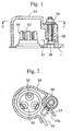
- Fig. 1 is an enlarged view of an main portion (terminal box) of a sealed-type compressor according to an embodiment of the present invention.
- Fig. 2 is a diagram showing a cross-sectional view along the line C-C of Fig. 1.
- Fig. 3 shows a longitudinal cross sectional view of the sealed-type compressor as a whole.
- Fig. 4 shows a partially exploded plan view of an example of a conventional sealed-type compressor.
- Fig. 5 shows a cross-sectional view of the terminal box shown in Fig. 4.
- Fig. 6 is a diagram showing a cross-sectional view along the line A-A of Fig. 5.
- Fig. 7 shows a cross-sectional view of an example of a conventional sealed-type compressors when it is necessary to apply an earth wire.
- Fig. 8 is a diagram showing a cross-sectional view along the line B-B of Fig. 7.
- the scroll-type compressor mechanism C comprises a stationary scroll member 13, an orbiting scroll member 14, an Oldham's ring 15 for obstructing autorotation of the orbiting scroll member, a frame 16 to which the stationary scroll member 13 is fixed, and an upper bearing 17a for supporting the rotating shaft 12.
- the stationary scroll member 13 is composed of an end plates 18 and an involute-shaped wrap 19 which are vertically mounted inside of the end plates 18, and an intake hole 20 is formed in the peripheral wall and an exhaust port 22 is provided at the centers of the end plate 18 and the discharge cover 21.
- a discharge valve 23 for opening or closing the exhaust port 22 is also provided at the exhaust port 22.
- the orbiting scroll member 14 is provided with an end plates 24 and an involute-shaped wrap 25 which is vertically arranged inside the end plates 24.
- An eccentric bush 27 is rotatably fitted in a boss 26, vertically provided at the rear surface of the end plates 24, and an eccentric pin, which protrudes from the top end of the rotating shaft 12, is rotatably inserted into a hole formed in the eccentric bush 27.
- the scroll-type compressor mechanism is constructed such that a plurality of sealed spaces 28 are formed by positioning the stationary scroll member 13 and the orbiting scroll member 14 into an eccentric engagement separated at a designated distance and by shifting one of the stationary scroll member and the orbiting scroll member in an orbiting direction of the orbiting scroll member by 180 degrees.
- the stationary scroll member 13 and the orbiting scroll member 14 are mounted on the upper surface of the frame 16 fixed to the sealing housing 11, and the rotating shaft 12 is rotatably supported by the upper bearing 17a and the lower bearing 17b.
- the lead wire 31 of the motor M is connected to the inside of the terminal 32 fixed to the sealing housing 11 and the outside of the terminal 32 is protected by the plastic cover 33 (the terminal box).
- the terminal 32 and the plastic cover 33 are constructed by the same structure as the conventional structure and an opening 33a is formed in the plastic cover 33 for admitting the wiring from the power supply and the earth wire 34.
- a screw is formed from the base to the top of the bolt 35 welded to the sealing housing 11 such that the nut 36 for fixing the plastic cover 33 to the sealing housing 11 and the nut 38 for connecting the earth terminal to the bolt 35 are engaged to the screw of the bolt.
- connection is simply achieved by passing the earth terminal through the bolt and by fixing it by the nut 38.
- the wiring from the power supply is connected with the terminal 32 and, while the wiring and the earth wire 34 pass through the opening 33a, the plastic cover 33 is abutted to the sealing housing 11 by setting the plastic cover 33 to pass over the bolt 35.
- the plastic cover 33 is fixed to the sealing housing 11 by screwing the nut 36 into the bolt 35.
- the sealed-type compressor according to an embodiment of the present invention, it is possible to use the same terminal box (plastic cover 33) as the conventional terminal box in any cases irrespective of whether or not the earth is necessary.
- the conventional terminal box (plastic cover 33) has been used when the earth is not necessary.
- the sealed-type compressor of the present invention since almost the same terminal box as the conventional one can be used in any cases irrespective of whether or not the earth is necessary, the sealed-type compressor of the present invention does not need to provide another type of the terminal box and reduced cost is realized.
- the earth terminal is not directly fixing the terminal box of the sealing housing, but the earth terminal is designed such that it can be assembled with a fixing means for fixing the terminal box to the sealing housing.
- the same terminal box can be used irrespective of whether or not the earth is necessary, the sealed-type compressor of the present invention does not need to provide another type of the terminal box, and reduced cost is realized.
Landscapes
- Engineering & Computer Science (AREA)
- Power Engineering (AREA)
- Mechanical Engineering (AREA)
- General Engineering & Computer Science (AREA)
- Compressor (AREA)
- Applications Or Details Of Rotary Compressors (AREA)
- Rotary Pumps (AREA)
Applications Claiming Priority (2)
| Application Number | Priority Date | Filing Date | Title |
|---|---|---|---|
| JP20407498 | 1998-07-17 | ||
| JP10204074A JP3025236B2 (ja) | 1998-07-17 | 1998-07-17 | 密閉型圧縮機 |
Publications (2)
| Publication Number | Publication Date |
|---|---|
| EP0973233A1 true EP0973233A1 (de) | 2000-01-19 |
| EP0973233B1 EP0973233B1 (de) | 2002-11-27 |
Family
ID=16484350
Family Applications (1)
| Application Number | Title | Priority Date | Filing Date |
|---|---|---|---|
| EP99304982A Expired - Lifetime EP0973233B1 (de) | 1998-07-17 | 1999-06-24 | Zusammenbau eines Anschlussgehäuses eines Verdichters vom abgedichteten Typ |
Country Status (5)
| Country | Link |
|---|---|
| US (1) | US20010001638A1 (de) |
| EP (1) | EP0973233B1 (de) |
| JP (1) | JP3025236B2 (de) |
| CN (1) | CN1087402C (de) |
| DE (1) | DE69904120T2 (de) |
Cited By (2)
| Publication number | Priority date | Publication date | Assignee | Title |
|---|---|---|---|---|
| FR2977736A1 (fr) * | 2011-07-08 | 2013-01-11 | Danfoss Scroll Technologies Llc | Connexion de borne pour compresseur hermetique |
| EP2169180A4 (de) * | 2007-06-05 | 2016-03-30 | Daikin Ind Ltd | Strömungsmaschine |
Families Citing this family (10)
| Publication number | Priority date | Publication date | Assignee | Title |
|---|---|---|---|---|
| JP3600781B2 (ja) * | 2000-06-06 | 2004-12-15 | 株式会社日立製作所 | 密閉形電動圧縮機用保護装置、並びにこれを用いた密閉形電動圧縮機及び冷却システム |
| US7108489B2 (en) * | 2003-04-15 | 2006-09-19 | Tecumseh Products Company | Terminal block assembly for a hermetic compressor |
| US8313343B2 (en) * | 2010-08-31 | 2012-11-20 | Hamilton Sundstrand Corporation | Terminal block cover with nut retention feature |
| CN102594006A (zh) * | 2011-01-10 | 2012-07-18 | 伍宏斌 | 一种振动电机接线盒用绝缘垫板 |
| JP5358609B2 (ja) * | 2011-03-31 | 2013-12-04 | 株式会社小松製作所 | 発電電動機および作業機械 |
| US8801400B2 (en) * | 2011-07-08 | 2014-08-12 | Danfoss Scroll Technologies Llc | Secure connection terminal for hermetic compressor |
| CN104265638B (zh) * | 2014-09-18 | 2016-08-31 | 乔建设 | 低电压强电流进排气口可变位式电动涡旋压缩机 |
| CN107514364B (zh) * | 2016-06-18 | 2021-12-07 | 上海海立电器有限公司 | 一种压缩机 |
| CN107100846B (zh) | 2017-04-28 | 2020-05-26 | 上海海立新能源技术有限公司 | 一种车用涡旋压缩机 |
| WO2025079908A1 (ko) * | 2023-10-12 | 2025-04-17 | 삼성전자주식회사 | 압축기 |
Citations (5)
| Publication number | Priority date | Publication date | Assignee | Title |
|---|---|---|---|---|
| EP0450153A2 (de) * | 1990-03-21 | 1991-10-09 | Tecumseh Products Company | Hermetischer Endstecker mit elektrisch isolierender Kappe |
| US5173057A (en) * | 1992-02-07 | 1992-12-22 | Tecumseh Products Company | Permanent protective cover |
| EP0562909A1 (de) * | 1992-03-24 | 1993-09-29 | Valeo Equipements Electriques Moteur | Anschlussklemmen für Drehstromgenerator eines Fahrzeuges |
| JPH07103161A (ja) * | 1993-09-30 | 1995-04-18 | Mitsubishi Heavy Ind Ltd | スクロ−ル型圧縮機 |
| US5664959A (en) * | 1995-12-15 | 1997-09-09 | Carrier Corporation | Electrical connector plug |
Family Cites Families (2)
| Publication number | Priority date | Publication date | Assignee | Title |
|---|---|---|---|---|
| AT396390B (de) * | 1987-11-16 | 1993-08-25 | Mayreder Kraus & Co Ing | Gebirgsanker |
| JP2543309Y2 (ja) | 1990-07-31 | 1997-08-06 | 岩崎電気株式会社 | 蛍光灯用安定器の取付構造 |
-
1998
- 1998-07-17 JP JP10204074A patent/JP3025236B2/ja not_active Expired - Lifetime
-
1999
- 1999-06-23 US US09/338,437 patent/US20010001638A1/en not_active Abandoned
- 1999-06-24 DE DE69904120T patent/DE69904120T2/de not_active Expired - Lifetime
- 1999-06-24 EP EP99304982A patent/EP0973233B1/de not_active Expired - Lifetime
- 1999-07-13 CN CN99110344A patent/CN1087402C/zh not_active Expired - Lifetime
Patent Citations (5)
| Publication number | Priority date | Publication date | Assignee | Title |
|---|---|---|---|---|
| EP0450153A2 (de) * | 1990-03-21 | 1991-10-09 | Tecumseh Products Company | Hermetischer Endstecker mit elektrisch isolierender Kappe |
| US5173057A (en) * | 1992-02-07 | 1992-12-22 | Tecumseh Products Company | Permanent protective cover |
| EP0562909A1 (de) * | 1992-03-24 | 1993-09-29 | Valeo Equipements Electriques Moteur | Anschlussklemmen für Drehstromgenerator eines Fahrzeuges |
| JPH07103161A (ja) * | 1993-09-30 | 1995-04-18 | Mitsubishi Heavy Ind Ltd | スクロ−ル型圧縮機 |
| US5664959A (en) * | 1995-12-15 | 1997-09-09 | Carrier Corporation | Electrical connector plug |
Non-Patent Citations (1)
| Title |
|---|
| PATENT ABSTRACTS OF JAPAN vol. 095, no. 007 31 August 1995 (1995-08-31) * |
Cited By (2)
| Publication number | Priority date | Publication date | Assignee | Title |
|---|---|---|---|---|
| EP2169180A4 (de) * | 2007-06-05 | 2016-03-30 | Daikin Ind Ltd | Strömungsmaschine |
| FR2977736A1 (fr) * | 2011-07-08 | 2013-01-11 | Danfoss Scroll Technologies Llc | Connexion de borne pour compresseur hermetique |
Also Published As
| Publication number | Publication date |
|---|---|
| JP2000034990A (ja) | 2000-02-02 |
| EP0973233B1 (de) | 2002-11-27 |
| CN1087402C (zh) | 2002-07-10 |
| US20010001638A1 (en) | 2001-05-24 |
| DE69904120D1 (de) | 2003-01-09 |
| JP3025236B2 (ja) | 2000-03-27 |
| CN1242477A (zh) | 2000-01-26 |
| DE69904120T2 (de) | 2003-07-17 |
Similar Documents
| Publication | Publication Date | Title |
|---|---|---|
| EP0973233A1 (de) | Verdichter vom abgedichteten Typ | |
| US6866487B2 (en) | Compressor with built-in motor and mobile structure using the same | |
| CN107013460B (zh) | 一种压缩机 | |
| KR102289268B1 (ko) | 전동 압축기 | |
| EP1277961B1 (de) | Spiralverdichter | |
| US8777594B2 (en) | Compressor having wire retainer | |
| JP2011069311A (ja) | 圧縮機、組立方法 | |
| US11486393B2 (en) | Scroll compressor for vehicle | |
| JP7262971B2 (ja) | 電動圧縮機 | |
| CN107013463B (zh) | 一种压缩机 | |
| CN107023482B (zh) | 一种压缩机 | |
| CN106989018B (zh) | 一种压缩机 | |
| JP4018367B2 (ja) | 電動式圧縮機 | |
| WO2023248703A1 (ja) | 電動圧縮機 | |
| JP5045550B2 (ja) | 電動コンプレッサ | |
| JP3051701B2 (ja) | 密閉型スクロール圧縮機 | |
| US7708532B2 (en) | Electric compressor | |
| CN107023483B (zh) | 一种压缩机 | |
| JP3327702B2 (ja) | スクロール型圧縮機 | |
| JP2559430B2 (ja) | 密閉形スクロール圧縮機 | |
| WO2023248707A1 (ja) | 電動圧縮機及びその製造方法 | |
| JPH0893662A (ja) | スクロール圧縮機 | |
| JP2000179485A (ja) | スクロール型圧縮機 | |
| JPH08109885A (ja) | スクロール型圧縮機の組立方法及び組立治具 | |
| JP2009030485A (ja) | 電装品箱ならびに電装品箱を備える圧縮機 |
Legal Events
| Date | Code | Title | Description |
|---|---|---|---|
| PUAI | Public reference made under article 153(3) epc to a published international application that has entered the european phase |
Free format text: ORIGINAL CODE: 0009012 |
|
| 17P | Request for examination filed |
Effective date: 19990713 |
|
| AK | Designated contracting states |
Kind code of ref document: A1 Designated state(s): DE GB IT NL |
|
| AX | Request for extension of the european patent |
Free format text: AL;LT;LV;MK;RO;SI |
|
| 17Q | First examination report despatched |
Effective date: 20000626 |
|
| AKX | Designation fees paid |
Free format text: DE GB IT NL |
|
| GRAG | Despatch of communication of intention to grant |
Free format text: ORIGINAL CODE: EPIDOS AGRA |
|
| RTI1 | Title (correction) |
Free format text: TERMINAL BOX ASSEMBLY OF A SEALED-TYPE COMPRESSOR |
|
| GRAG | Despatch of communication of intention to grant |
Free format text: ORIGINAL CODE: EPIDOS AGRA |
|
| GRAH | Despatch of communication of intention to grant a patent |
Free format text: ORIGINAL CODE: EPIDOS IGRA |
|
| GRAH | Despatch of communication of intention to grant a patent |
Free format text: ORIGINAL CODE: EPIDOS IGRA |
|
| GRAA | (expected) grant |
Free format text: ORIGINAL CODE: 0009210 |
|
| AK | Designated contracting states |
Kind code of ref document: B1 Designated state(s): DE GB IT NL |
|
| REG | Reference to a national code |
Ref country code: GB Ref legal event code: FG4D |
|
| REF | Corresponds to: |
Ref document number: 69904120 Country of ref document: DE Date of ref document: 20030109 |
|
| PGFP | Annual fee paid to national office [announced via postgrant information from national office to epo] |
Ref country code: GB Payment date: 20030613 Year of fee payment: 5 |
|
| PGFP | Annual fee paid to national office [announced via postgrant information from national office to epo] |
Ref country code: NL Payment date: 20030630 Year of fee payment: 5 |
|
| PLBE | No opposition filed within time limit |
Free format text: ORIGINAL CODE: 0009261 |
|
| STAA | Information on the status of an ep patent application or granted ep patent |
Free format text: STATUS: NO OPPOSITION FILED WITHIN TIME LIMIT |
|
| 26N | No opposition filed |
Effective date: 20030828 |
|
| PG25 | Lapsed in a contracting state [announced via postgrant information from national office to epo] |
Ref country code: GB Free format text: LAPSE BECAUSE OF NON-PAYMENT OF DUE FEES Effective date: 20040624 |
|
| PG25 | Lapsed in a contracting state [announced via postgrant information from national office to epo] |
Ref country code: NL Free format text: LAPSE BECAUSE OF NON-PAYMENT OF DUE FEES Effective date: 20050101 |
|
| GBPC | Gb: european patent ceased through non-payment of renewal fee |
Effective date: 20040624 |
|
| NLV4 | Nl: lapsed or anulled due to non-payment of the annual fee |
Effective date: 20050101 |
|
| PG25 | Lapsed in a contracting state [announced via postgrant information from national office to epo] |
Ref country code: IT Free format text: LAPSE BECAUSE OF NON-PAYMENT OF DUE FEES;WARNING: LAPSES OF ITALIAN PATENTS WITH EFFECTIVE DATE BEFORE 2007 MAY HAVE OCCURRED AT ANY TIME BEFORE 2007. THE CORRECT EFFECTIVE DATE MAY BE DIFFERENT FROM THE ONE RECORDED. Effective date: 20050624 |
|
| PGFP | Annual fee paid to national office [announced via postgrant information from national office to epo] |
Ref country code: DE Payment date: 20180612 Year of fee payment: 20 |
|
| REG | Reference to a national code |
Ref country code: DE Ref legal event code: R082 Ref document number: 69904120 Country of ref document: DE Representative=s name: LEINWEBER & ZIMMERMANN, DE Ref country code: DE Ref legal event code: R081 Ref document number: 69904120 Country of ref document: DE Owner name: MITSUBISHI HEAVY INDUSTRIES THERMAL SYSTEMS, L, JP Free format text: FORMER OWNER: MITSUBISHI HEAVY INDUSTRIES, LTD., TOKYO, JP |
|
| REG | Reference to a national code |
Ref country code: DE Ref legal event code: R071 Ref document number: 69904120 Country of ref document: DE |