EP0973239A2 - Circuit protecteur - Google Patents
Circuit protecteur Download PDFInfo
- Publication number
- EP0973239A2 EP0973239A2 EP99113436A EP99113436A EP0973239A2 EP 0973239 A2 EP0973239 A2 EP 0973239A2 EP 99113436 A EP99113436 A EP 99113436A EP 99113436 A EP99113436 A EP 99113436A EP 0973239 A2 EP0973239 A2 EP 0973239A2
- Authority
- EP
- European Patent Office
- Prior art keywords
- switching device
- control system
- protective switching
- switch
- current
- Prior art date
- Legal status (The legal status is an assumption and is not a legal conclusion. Google has not performed a legal analysis and makes no representation as to the accuracy of the status listed.)
- Granted
Links
- 230000001681 protective effect Effects 0.000 title claims abstract description 66
- 238000012544 monitoring process Methods 0.000 claims abstract description 12
- 238000001514 detection method Methods 0.000 claims description 13
- 230000006870 function Effects 0.000 claims description 12
- 238000000926 separation method Methods 0.000 claims description 7
- 230000003213 activating effect Effects 0.000 claims description 4
- 238000012360 testing method Methods 0.000 claims description 4
- 238000002955 isolation Methods 0.000 claims description 3
- 230000000903 blocking effect Effects 0.000 claims 1
- 230000001939 inductive effect Effects 0.000 description 3
- 230000011664 signaling Effects 0.000 description 3
- 230000001960 triggered effect Effects 0.000 description 3
- 230000007547 defect Effects 0.000 description 2
- 238000010586 diagram Methods 0.000 description 2
- 238000005259 measurement Methods 0.000 description 2
- 230000003287 optical effect Effects 0.000 description 2
- 230000004913 activation Effects 0.000 description 1
- 239000003086 colorant Substances 0.000 description 1
- 239000004020 conductor Substances 0.000 description 1
- 230000003111 delayed effect Effects 0.000 description 1
- 238000011161 development Methods 0.000 description 1
- 238000003306 harvesting Methods 0.000 description 1
- 239000011159 matrix material Substances 0.000 description 1
- 238000012545 processing Methods 0.000 description 1
- 230000009993 protective function Effects 0.000 description 1
- 239000004065 semiconductor Substances 0.000 description 1
- 238000011144 upstream manufacturing Methods 0.000 description 1
- 230000000007 visual effect Effects 0.000 description 1
Images


Classifications
-
- H—ELECTRICITY
- H02—GENERATION; CONVERSION OR DISTRIBUTION OF ELECTRIC POWER
- H02H—EMERGENCY PROTECTIVE CIRCUIT ARRANGEMENTS
- H02H11/00—Emergency protective circuit arrangements for preventing the switching-on in case an undesired electric working condition might result
- H02H11/002—Emergency protective circuit arrangements for preventing the switching-on in case an undesired electric working condition might result in case of inverted polarity or connection; with switching for obtaining correct connection
-
- H—ELECTRICITY
- H02—GENERATION; CONVERSION OR DISTRIBUTION OF ELECTRIC POWER
- H02H—EMERGENCY PROTECTIVE CIRCUIT ARRANGEMENTS
- H02H3/00—Emergency protective circuit arrangements for automatic disconnection directly responsive to an undesired change from normal electric working condition with or without subsequent reconnection ; integrated protection
- H02H3/02—Details
- H02H3/04—Details with warning or supervision in addition to disconnection, e.g. for indicating that protective apparatus has functioned
-
- H—ELECTRICITY
- H02—GENERATION; CONVERSION OR DISTRIBUTION OF ELECTRIC POWER
- H02H—EMERGENCY PROTECTIVE CIRCUIT ARRANGEMENTS
- H02H3/00—Emergency protective circuit arrangements for automatic disconnection directly responsive to an undesired change from normal electric working condition with or without subsequent reconnection ; integrated protection
- H02H3/08—Emergency protective circuit arrangements for automatic disconnection directly responsive to an undesired change from normal electric working condition with or without subsequent reconnection ; integrated protection responsive to excess current
- H02H3/087—Emergency protective circuit arrangements for automatic disconnection directly responsive to an undesired change from normal electric working condition with or without subsequent reconnection ; integrated protection responsive to excess current for DC applications
-
- H—ELECTRICITY
- H01—ELECTRIC ELEMENTS
- H01H—ELECTRIC SWITCHES; RELAYS; SELECTORS; EMERGENCY PROTECTIVE DEVICES
- H01H9/00—Details of switching devices, not covered by groups H01H1/00 - H01H7/00
- H01H9/54—Circuit arrangements not adapted to a particular application of the switching device and for which no provision exists elsewhere
- H01H9/548—Electromechanical and static switch connected in series
-
- H—ELECTRICITY
- H02—GENERATION; CONVERSION OR DISTRIBUTION OF ELECTRIC POWER
- H02H—EMERGENCY PROTECTIVE CIRCUIT ARRANGEMENTS
- H02H3/00—Emergency protective circuit arrangements for automatic disconnection directly responsive to an undesired change from normal electric working condition with or without subsequent reconnection ; integrated protection
- H02H3/02—Details
- H02H3/05—Details with means for increasing reliability, e.g. redundancy arrangements
Definitions
- the invention relates to a protective switching device for a load circuit, with at least two between an operating voltage input and one Switching output for the current paths running through the load.
- Such a protective switching device serves to protect the lines of a Load circuit and a switch arranged in this switch against short circuit or overload.
- the load circuit is connected to the outer conductor a supply or operating voltage connected via the protective switching device, which switches off the load or control circuit in the event of a fault.
- the Protective switching device or the protective switching device usually comprises one Current path an operable or controllable switch that opens in the event of an error and thus isolates the load circuit from the operating voltage with one pole.
- Such a single-pole switching protective device is in particular in the event of a ground fault, it does not ensure that a in the load circuit Switched consumer reliably stopped even when the protective function is triggered or is switched off.
- a in the load circuit Switched consumer reliably stopped even when the protective function is triggered or is switched off.
- one in the load circuit switched machine in the event of an earth fault occurring on both sides of the switch unintentionally start even with the switch open and thus in In the event of an error-related shutdown, they cannot be reliably protected.
- the invention is therefore based on the object of a protective switching device Specify the type mentioned above, the reliable protection of a load circuit and its components in the event of a fault, especially in the event of a fault an earth fault.
- an electronic switch is provided in each current path, with a control system for monitoring and all-pole switching off of the Load circuit is connected.
- controllable electronic switches are in particular bipolar transistors, FET, e.g. B. MOS transistors, and intelligent Power semiconductors suitable.
- the protective switching device is particularly suitable for ohmic and inductive loads with a nominal direct voltage (DC) of 5V to 300V, preferably 12V to 60V, in particular of 24 V (DC), and a maximum nominal current of 20A, especially 3A.
- DC direct voltage
- a load circuit switched consumers or actuators, e.g. a solenoid valve, a magnetic brake or a motor, all-pole in machines and systems and thus in the case of one DC operating voltage switched two-pole.
- the protective switching device the electrical functionality of the actuators or Consumer monitors and the lines of the load circuit reliably protected.
- the Protective switching device in at least one current path a switch contact is coupled to a (first) relay which can be controlled by the control system.
- the control system of the protective switching device is used in particular for monitoring the functionality of the overall system between the operating voltage input the protective switching device and the load in the load circuit. she also serves to monitor internal faults within the protective switching device itself.
- the control system is used to control the electronic and possibly the electromechanical switch for implementation the start and stop functions of the actuator or the ON and OFF functions of the consumer in the load circuit and for all-pole shutdown both in error-free operation (normal operation) and in the event of an error.
- the control system is used to control preferably optical display elements for signaling the respective external error and an internal one Errors and to report operational readiness in error-free condition. Further the control system is used to control an error message output Connection of an external switching status display and for error storage.
- the control system receives both on and off State of the protective switching device at least one from an operating parameter derived function signal and generates when it deviates an error message from a predefinable reference or comparison value and a control signal for switching off the load circuit.
- an operating parameter derived function signal For function monitoring be particularly for the switching state of the electronic switch characteristic operating parameters, such as B. their leakage current or voltage level, as well as the load current flowing over the or each current path.
- the control system determines on the basis of a deviation of these operating data or measured values from given reference values taking into account the Switching state the type of an error that has occurred and generates a corresponding one Error signal.
- the control system advantageously monitors the deviation for wire break detection of the current detected in at least one current path from a reference value. Falls below z. B. in the off state of the or everyone electronic switch flowing leakage current a minimum current value or falls below a predetermined minimum current when switched on Lower limit, e.g. B. I ⁇ 50mA, wire breakage in the load circuit is detected and a corresponding error signal and a control signal for switching off the Load circuit issued. Alternatively, a voltage level can also be measured and compared with a corresponding minimum level.
- the control system monitors for short-circuit detection when switched off expediently a test current conducted over the load circuit. in the switched on state in the event of a deviation in at least one Current path detected load current from a predetermined reference value to short circuit or overload detected. If the detected load current exceeds a predetermined one Maximum value, the control system in turn generates a corresponding one Error message and a control signal to lock the electronic switch.
- the load circuit is delayedly switched off depending on the overload.
- the control system is advantageously controlled by means of a Load circuit galvanically isolated control circuit.
- the galvanic isolation the control circuit from the load circuit can, for example, by means of a Optocouplers can be realized.
- the Control system coupled (second) relay provided in the form of a small signal relay.
- the control circuit there is also a control current display, preferably in the form of a light-emitting diode.
- the Control circuit expediently a reverse polarity protection, preferably in the form a diode connected in this, in addition, a coupled with the relay Switch for internal and / or external feedback of a control signal be provided.
- the protective switching device has a switching unit controlled by the control system, with a control button to deactivate error storage and with a first Switch for activating the external status display is coupled.
- a control button for activating the external status display is coupled.
- the switching unit expediently comprises a second one Switch between the preferably monostable first relay Electromechanical separation of the load circuit and the operating voltage input the protective switching device is switched.
- the control of the switching unit is expediently carried out with a Control system connected trigger switch, such as a magnetic Type 808 circuit breaker from E-T-A, and a coupled to it Switch lock that interacts with the control button and the two switches.
- a Control system connected trigger switch such as a magnetic Type 808 circuit breaker from E-T-A
- Switch lock that interacts with the control button and the two switches.
- At least one current path Current measuring device provided in the form of a measuring shunt. This is with voltage taps provided on the one hand for external current detection by means of a Voltmeters to one connection of the protective switching device and on the other for internal processing of the corresponding function signal to the Tax system are managed.
- the operating voltage input is also an advantageous embodiment of the protective switching device reverse polarity protected.
- the is expedient Trigger switch provided, the drive coil on the connection side two diodes connected to each other connected to the operating voltage inputs is.
- a transistor is provided for external control Collector-emitter path via two of the four reverse polarity protection diodes between the operating voltage inputs are switched.
- the trigger switch comprises diodes connected in the manner of a Grford bridge with a controllable transistor in a diode branch.
- the one in the DC output the drive coil lying on the bridge is for self-interruption coupled to the switch via the key switch.
- the transistor can also be actively interrupted.
- the advantages achieved by the invention are in particular that means a protective device with an electronically switchable switching output ensures a reliable shutdown of the load circuit to be protected is.
- the internal electronic control system to control the in each Current path provided electronic switch also enables a reliable monitoring of the entire system for external and internal errors.
- the monitoring of the entire system by means of the control system of the protective switching device also enables a differentiated error message Both external and internal errors through an appropriate visual display. Furthermore, an internal controlled by the control system ensures Switch unit error storage, which is advantageously only by manual Operation can be reset. One that can be tapped at the protective switching device Switching status display also enables the connection of a external error message display, for example for a higher-level control system.
- the protective switching device 1 shown schematically in Fig. 1, hereinafter also referred to as a protective switching relay, comprises two current paths 2, 3, each with a controllable electronic switch 4 or 5, for example, each with a power transistor, between an operating voltage input ( ⁇ ) U B and a switching output ( ⁇ ) U L for connecting a load circuit 6 of an ohmic or inductive load L, for example.
- a controllable electronic switch 4 or 5 for example, each with a power transistor
- ⁇ operating voltage input
- ⁇ switching output
- L for example an actuator in a machine or system
- the load L can also be capacitive or, in a simple application, a lamp.
- connection K 41 to K 44 e.g. B. in the form of terminals, of which the connections K 41 and K 43 serve to connect a further protective switching device or protective switching relay to the operating voltage U B.
- Connections K 31 and K 32 are provided for connecting the load circuit 6, ie its lines 6a, 6b to the switching or load output ( ⁇ ) U L of the protective switching relay 1.
- a free-wheeling diode 8 is connected between the two current paths 2 and 3.
- a measuring shunt 9 for current measurement is connected in one of the two current paths - in the exemplary embodiment in current path 2.
- the measuring shunt 9 is connected via signal lines 10, 11 to a control system 12 in the form of control electronics of the protective switching relay 1.
- the measuring shunt 9 has, for example, a resistance value of 0.1 ⁇ with a tolerance of 1%.
- the control system 12 is also connected to the electronic switches 4 and 5 via control and signal lines 14, 15. Furthermore, the control system 12 is connected on the input side to the connections K 41 , K 43 and thus to the operating voltage U B. In addition, the control system 12 is connected on the output side via a signal line 16 to a display panel 17 with light-emitting diodes (LED) of different colors, for example.
- LED light-emitting diodes
- a control circuit 18 which is galvanically isolated from the load circuit 6.
- the relay coil of a (second) relay 19 is connected in the control circuit 18, which is advantageously connected in parallel with a free-wheeling diode 20 to protect the control circuit 18 against impermissibly high voltage pulses.
- the relay 19, which is preferably designed as a small signal relay, is connected on the one hand via a control current display 21, for example in the form of a light-emitting diode, to connections K 13 and K 14 for the negative pole of a control voltage U S.
- the small signal relay 19 is connected via a diode 22 connected in the forward direction to a connection K 11 for the positive pole of the control voltage U S.
- the diode 22 serves as reverse polarity protection of the control circuit 18.
- the small signal relay 19 is coupled to a control input 23 of the control system 12 via a contact.
- the relay 19 is coupled to a feedback switch or switch contact 24, via which a feedback signal S R can be called up internally and / or externally when the control current I S is flowing.
- the control system 12 is on the output side via a control output 25 with a Switch unit 26 connected. This includes one connected to the control output 25 and drive coil 27 cooperating with a switching lock 28 a trigger switch.
- the switching lock 28 has a first switch 29 or switching contact coupled in the form of a closer. Furthermore, that is Switch lock 28 with an externally actuable control button 30 for manual Locking the key switch 28 coupled. Furthermore, the switching lock 28 coupled to a second switch 31 which is connected to a harvesting relay 32 is.
- the drive coil 27 and the switching lock 28 and the switches 29, 31 form within the switching unit 26 together with the control button 30 Trigger switch.
- the relay 32 is connected to the positive pole of the operating voltage U B via the second switch 31 and a diode 33 serving as reverse polarity protection.
- the relay 32 is used to actuate a switch contact 34, 35 in the current path 2 and 3, respectively.
- the arrangement of the switch contacts 34 and 35 in the respective current path 2 and 3 is only exemplary. Each of the switch contacts 34, 35 can thus be provided both in front of and behind the corresponding electronic switch 4 or 5. Instead of two switching contacts 34, 35, only one switching contact 34 or 35 can be provided in one of the current paths 2 or 3.
- the protective switching device 1 is used primarily for all-pole, ie in the exemplary embodiment for two-pole, switching of the load L.
- the protection relates in particular to the lines 6a, 6b of the load circuit 6.
- the protective switching device 1 serves to monitor the electrical functionality of the load circuit 6 as Load L switched consumer. It also serves to signal the operating state and to display, in particular for the optical display, load circuit faults and their reporting via a potential-free signal contact which is implemented by the switch 29. For this purpose, this is connected to connections K 21 to K 24 for connecting an external error message display.
- the connections K 21 and K 23 are electrically conductively connected to one another internally in the illustrated closed position of the switch 29 and the manually pulled out or electronically triggered control button 30.
- the control system 12 evaluates current operating states and, on the one hand, generates control signals in the event of a fault for the two-pole electronic shutdown of the switching output ( ⁇ ) U L and for the subsequent, at least single-pole, electromechanical separation of the load circuit 6 from the operating voltage input ( ⁇ ) U B.
- the control system 12 generates message signals for controlling different colored light-emitting diodes for different types of errors in the display field 17.
- the control system 12 activates the error storage in the form of the triggered control button 30 via the switching unit 26 and the integrated error message for the external switching status display via the connections K 21 to K 24 .
- the monitoring is carried out both in the switched-on and in the switched-off state of the load L connected to the protective switching device 1 via the load circuit 6.
- the control system 12 receives a number of function signals F 1 ... n in Form of operating parameters recorded directly or derived from measured values. These are, in particular, the switching state reported by the lines 14, 15 from the electronic switches 4 and 5, the current value of the load current I L flowing through the load circuit 6 when switched on or the leakage current I L ' flowing through the load circuit 6 when switched off State and via the control input 23 the control level of the control circuit 18.
- control level For example, for a control voltage U S between 0 V and 2.4 V (DC) the control level is "0", while the control level “1" is for a control voltage U S between 18 V and 32 V (DC).
- the control current I S is, for example, in the range between 5 mA and 10 mA at a maximum switching frequency of 10 Hz, for example.
- the monitoring of the load circuit 6 and thus the detection of external faults and the detection of internal faults within the protective switching relay 1 as well as the all-pole disconnection of the load circuit 6 and its subsequent electromagnetic separation from the switching output ( ⁇ ) U L takes place on the basis of the different operational function signals F 1 .. .n , which are evaluated by the control system 12 using a status matrix or status logic . So is in trouble-free operation at a control level 0 "of the control circuit 18, the load or switching output ( ⁇ ) U L via the two electronic switches 4, 5 is blocked. This corresponds to the switched-off state or switching state" OFF ".
- the or each switching contact 34, 35 is closed, so that the switching output ( ⁇ ) U L and the operating voltage input ( ⁇ ) U B are electrically connected to one another.
- the control system 12 generates a message signal S M for the display field 17, in which, for example, a green light-emitting diode indicates the operational readiness of the protective switching relay 1 and the absence of errors in the load circuit 6.
- the relay 32 is secured via diode 33 against polarity reversal of the operating voltage input U B , since if the polarity is reversed, the relay 32 is de-energized and the switch contacts 34, 35 are thus open. In addition, even if the polarity is reversed, the actuation button 30 is in the OFF position.
- the control level changes from 0 "on 1 ", the two electronic switches 4 and 5 are controlled by the control system 12 and the load or switching output ( ⁇ ) U L is switched with two poles. With this switched-on state or switching state” ON “, the or each switching contact 34, 35 is still closed
- the control current indicator 21 is also activated, and the feedback signal S R is generated, which can be used as a further function signal F n , and this state is maintained as long as the load current detected via the measuring shunt 9 I L does not exceed a predetermined maximum value, for example 3 A, or does not fall below a predetermined minimum current I M , for example 0.1 A.
- the reference values R 1 ... n used for the comparison and assigned to the respective function signals F 1 ... n - represented by the arrow 36 - are preferably generated within the control system 12 t.
- a short-circuit or earth fault and an overload are detected when the control level is "1" and thus in the switched-on state when the detected load current I L exceeds the maximum value.
- the switching output ( ⁇ ) U L is blocked by the control system 12 by controlling the electronic switches 4, 5.
- the switching unit 25 controlled via the control system 12 there is additionally a delayed electromechanical separation of the load circuit 6 from the protective switching device 1 by opening the switch 31 and thus disconnecting the relay 32 from the operating voltage input ( ⁇ ) U B.
- the delay time is z. B. one second (1s).
- the additional electromechanical separation of at least one current path 2, 3 following an all-pole electronic shutdown also prevents a current from the load circuit 6, and thus via the actuator, from flowing in the event of a defect in the or each electronic switch 4, 5 or consumer L is led.
- the switch 29 is closed via the switching lock 28, so that an external switching status display connected to the connections K 21 to K 24 is activated.
- the display unit 17 receives, via the signal line 16, a control signal S M from the control system 12 for activating a light-emitting diode (eg red LED) which indicates the overload or the short circuit.
- a light-emitting diode eg red LED
- the actuating button 30 is guided into its OFF position by means of the switch lock 28.
- a test current I P is advantageously conducted via the load circuit 6 for short-circuit detection and / or wire break detection, which is detected by means of the measuring shunt 9 and monitored by the control system 12 with regard to a deviation from a corresponding reference value R n .
- Wire breaks in the load circuit occur both when switched off - ie at a control level 0 "and deactivated control current display 21 - as well as in the switched-on state - ie at a control level 1 "and activated control current display 21 - recognized when the im 0 "state determined leakage current I L ' or in 1 "state flowing minimum current I M falls below the predetermined minimum value.
- the switching output ( ⁇ ) U L is blocked with two poles both in the switched on and in the switched off state.
- the load circuit 6 is then electromechanically separated by means of the or each switch contact 34 , 35. The error message again occurs on the one hand by closing the switch 29 and opening the switch 31, and on the other hand by actuating a further light-emitting diode of the display unit 17 (for example orange LED) Position.
- the control is also carried out the z. B. red LED of the display panel 17. Furthermore, by means of the key switch 28 the actuating button 30 is guided into its OFF position.
- the one shown by display field 17 remains Received an error picture and thus the error until reset by manual operation of the operating button 30 stored.
- an error message is also generated in the event of reverse polarity, e.g. none of the LEDs in display field 17 are activated becomes.
- the actuating button 30 is in his by means of the switch lock 28 OFF position.
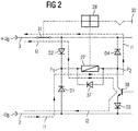
- a preferred reverse polarity protection for the operating voltage input ( ⁇ ) U B is shown in Figures 2 and 3.
- two series connections, each with two diodes D1 to D4 in the manner of a so-called Griger bridge, are provided between the positive pole and the negative pole of the operating voltage U B.
- the two diodes D1, D2 and D3, D4 are connected in opposite directions to one another within the series connections.
- the reverse polarity protection also includes a relay module in the form of the drive coil 27, which is connected between the two diodes D1, D2 and D3, D4.
- the relay module 27, to which a free-wheeling diode 37 is connected in parallel here, is coupled to the switch 31, which in the exemplary embodiment is provided in the current path 3 assigned to the positive pole of the operating voltage U B.
- the relay module 27 can also be controlled by means of a transistor 38 which, in the case of the npn transistor 38 shown in the exemplary embodiment, is connected between the diodes D3 and D4 connected on the cathode side to the current paths 2 and 3 and thus into the diode branch D3, D4.
- the collector is connected to the relay module 27.
- a pnp transistor 38 '(FIG. 3) this is connected between the diodes D1 and D2 connected on the anode side to the current paths 2 and 3 and thus into the diode branch D1, D2.
- the relay module or the drive coil 27 is located in the bridge output P 1,2 and is coupled via the switching lock 28 to the switch 31 assigned to the positive pole of the operating voltage U B.
- the trigger switch thus includes the diodes D1 to D4 and the transistor 38, 38 'in addition to the relay module or the drive coil 27 and the switching mechanism 28 and the switch 31.
- the diodes D2 and D3 are switched in the reverse direction, while the diodes D1 and D4 are conductive.
- the current thus flows in the technical current direction I 1 shown in dashed lines from the (-) U B pole via the diode D1 and the drive coil 27 and via the diode D4 to the (+) U B pole, so that the via the switching lock 28 with the drive coil 27 coupled switch 31 is opened and the current flow is interrupted.
- the polarity is correct, an interruption only occurs if the transistor 38 is controlled on the base side via the control system 12.
- the resulting current direction I 2 is also shown in dashed lines.
- the current directions I 1, 2 through the drive coil 27 are the same or in the same direction, both in the case of the automatic interruption in the event of polarity reversal and in the case of the interruption activated by means of the transistor 38 in the case of the correct polarity, in contrast to a conventional bridge circuit.
Landscapes
- Emergency Protection Circuit Devices (AREA)
- Protection Of Static Devices (AREA)
Applications Claiming Priority (4)
| Application Number | Priority Date | Filing Date | Title |
|---|---|---|---|
| DE19831030 | 1998-07-10 | ||
| DE19831030 | 1998-07-10 | ||
| DE19833984A DE19833984A1 (de) | 1998-07-10 | 1998-07-29 | Schutzschalteinrichtung |
| DE19833984 | 1998-07-29 |
Publications (3)
| Publication Number | Publication Date |
|---|---|
| EP0973239A2 true EP0973239A2 (fr) | 2000-01-19 |
| EP0973239A3 EP0973239A3 (fr) | 2000-05-10 |
| EP0973239B1 EP0973239B1 (fr) | 2001-12-12 |
Family
ID=26047350
Family Applications (1)
| Application Number | Title | Priority Date | Filing Date |
|---|---|---|---|
| EP99113436A Expired - Lifetime EP0973239B1 (fr) | 1998-07-10 | 1999-07-10 | Circuit protecteur |
Country Status (3)
| Country | Link |
|---|---|
| EP (1) | EP0973239B1 (fr) |
| AT (1) | ATE210902T1 (fr) |
| DE (1) | DE29824874U1 (fr) |
Cited By (5)
| Publication number | Priority date | Publication date | Assignee | Title |
|---|---|---|---|---|
| EP1137145A3 (fr) * | 2000-03-17 | 2005-10-05 | Alps Electric Co., Ltd. | Circuit contre la connexion inverse d'alimentation |
| EP1306955A3 (fr) * | 2001-10-26 | 2006-03-29 | Agco GmbH & Co. | Réseau à haute tension mobile |
| WO2007124775A1 (fr) * | 2006-04-29 | 2007-11-08 | Ellenberger & Poensgen Gmbh | Commutateur de sécurité électrique |
| EP1206025A3 (fr) * | 2000-11-07 | 2009-06-24 | Robert Bosch Gmbh | Dispositif de protection contre l'inversion des bornes de la batterie des éléments électriques |
| WO2024022840A1 (fr) * | 2022-07-28 | 2024-02-01 | Phoenix Contact Gmbh & Co.Kg | Appareil de coupure de tension continue et dispositif de commutation, en particulier pour la détection de défaut à la terre pendant un processus de mise en circuit pour la mise sous tension d'une charge de tension continue raccordée, et procédé pour faire fonctionner un appareil de coupure de tension continue ou un appareil de coupure de tension continue dispositif de commutation |
Families Citing this family (6)
| Publication number | Priority date | Publication date | Assignee | Title |
|---|---|---|---|---|
| DE202004008137U1 (de) * | 2004-05-22 | 2005-09-29 | Ellenberger & Poensgen Gmbh | Elektronisches Relais |
| DE102005017771B4 (de) * | 2005-04-13 | 2017-10-26 | Siemens Aktiengesellschaft | Verfahren zur Fertigung eines Niederspannungs-Leistungsschalter mit Eigenüberwachungsfunktionen |
| DE102010012135A1 (de) * | 2010-03-20 | 2011-09-22 | Volkswagen Ag | Verfahren zur Erkennung einer Verpolung und Verpolungserkennungseinrichtung |
| DE112011104896B4 (de) * | 2011-02-16 | 2015-10-22 | Toyota Jidosha Kabushiki Kaisha | Abgasreinigungssystem für ein Hybridfahrzeug und ein Steuerverfahren dafür |
| DE202016006183U1 (de) | 2016-10-05 | 2018-01-09 | WAGO Verwaltungsgesellschaft mit beschränkter Haftung | Zwei-polige elektrische Abschaltung |
| CN106786370A (zh) * | 2017-01-10 | 2017-05-31 | 洛阳师范学院 | 一种低压直流电源输出短路保护装置 |
Family Cites Families (4)
| Publication number | Priority date | Publication date | Assignee | Title |
|---|---|---|---|---|
| DD260152A1 (de) * | 1987-04-27 | 1988-09-14 | Leipzig Rft Nachrichtenelekt | Integrierbare schaltungsanordnung zum schutz elektronischer einrichtungen vor ueberspannung und ueberstrom |
| DE4136238A1 (de) * | 1991-11-02 | 1993-05-06 | Efn-Entwicklungsgesellschaft Fuer Nachrichtentechnik Mbh, O-1136 Berlin, De | Ueberstromschutzanordnung in gleichstromversorgungsnetz |
| FR2726698B1 (fr) * | 1994-11-04 | 1996-11-29 | Thomson Csf | Circuit de protection pour alimentation continue et alimentation associee a un tel circuit |
| US5546264A (en) * | 1994-12-22 | 1996-08-13 | Caterpillar Inc. | Reverse voltage protection circuit |
-
1998
- 1998-07-29 DE DE29824874U patent/DE29824874U1/de not_active Expired - Lifetime
-
1999
- 1999-07-10 EP EP99113436A patent/EP0973239B1/fr not_active Expired - Lifetime
- 1999-07-10 AT AT99113436T patent/ATE210902T1/de active
Cited By (8)
| Publication number | Priority date | Publication date | Assignee | Title |
|---|---|---|---|---|
| EP1137145A3 (fr) * | 2000-03-17 | 2005-10-05 | Alps Electric Co., Ltd. | Circuit contre la connexion inverse d'alimentation |
| EP1206025A3 (fr) * | 2000-11-07 | 2009-06-24 | Robert Bosch Gmbh | Dispositif de protection contre l'inversion des bornes de la batterie des éléments électriques |
| EP1306955A3 (fr) * | 2001-10-26 | 2006-03-29 | Agco GmbH & Co. | Réseau à haute tension mobile |
| US7187090B2 (en) | 2001-10-26 | 2007-03-06 | Agco Gmbh & Co. | Mobile high voltage network |
| WO2007124775A1 (fr) * | 2006-04-29 | 2007-11-08 | Ellenberger & Poensgen Gmbh | Commutateur de sécurité électrique |
| DE202006020498U1 (de) | 2006-04-29 | 2008-09-25 | Ellenberger & Poensgen Gmbh | Elektrischer Schutzschalter |
| WO2024022840A1 (fr) * | 2022-07-28 | 2024-02-01 | Phoenix Contact Gmbh & Co.Kg | Appareil de coupure de tension continue et dispositif de commutation, en particulier pour la détection de défaut à la terre pendant un processus de mise en circuit pour la mise sous tension d'une charge de tension continue raccordée, et procédé pour faire fonctionner un appareil de coupure de tension continue ou un appareil de coupure de tension continue dispositif de commutation |
| LU502584B1 (de) * | 2022-07-28 | 2024-02-01 | Phoenix Contact Gmbh & Co | Gleichspannungsschaltgerät und Schaltvorrichtung insbesondere zur Erdschlusserkennung während eines Einschaltvorgangs zum Einschalten einer angeschlossenen Gleichspannungslast sowie ein Verfahren zum Betreiben des Gleichspannungsschaltgeräts bzw. der Schaltvorrichtung |
Also Published As
| Publication number | Publication date |
|---|---|
| ATE210902T1 (de) | 2001-12-15 |
| EP0973239A3 (fr) | 2000-05-10 |
| DE29824874U1 (de) | 2003-04-30 |
| EP0973239B1 (fr) | 2001-12-12 |
Similar Documents
| Publication | Publication Date | Title |
|---|---|---|
| DE102016114740B3 (de) | Elektronische Sicherung für eine elektrische Last in einem Bordnetz eines Kraftfahrzeugs | |
| DE3215147C2 (fr) | ||
| DE69208799T2 (de) | Schutzschalter mit selektiver Verriegelung | |
| EP2593949B1 (fr) | Disjoncteur de surintensité, utilisation d'un disjoncteur de surintensité et véhicule électrique équipé d'un disjoncteur de surintensité | |
| DE4041672A1 (de) | Ueberwachungseinrichtung fuer einen gleichstromkreis sowie damit ausgeruestete photovoltaische energiegewinnungsanalge | |
| DE102008021542A1 (de) | Verfahren und eine Vorrichtung zur Überwachung von Hochvoltverbindungen eines Hybridfahrzeugs | |
| DE102005055325B3 (de) | Sicherheitsschaltvorrichtung zum fehlersicheren Abschalten eines elektrischen Verbrauchers | |
| EP0973239B1 (fr) | Circuit protecteur | |
| EP2980659A1 (fr) | Dispositif et procédé destinés à la surveillance et la commutation d'un circuit de charge | |
| DE4224620C1 (de) | Drehzahlüberwachungsgerät für Drehfeldmaschinen | |
| EP0359912A2 (fr) | Barrière électrique de sécurité antidéflagrante | |
| DE102016105036A1 (de) | Leistungsschaltervorrichtung | |
| EP0025913A2 (fr) | Circuit de sécurité pour la surveillance de soupapes magnétiques de véhicules | |
| DE19800049A1 (de) | Anordnung zum Übertragen von Daten und/oder Energie mit Trenneinheit | |
| DE10244961B3 (de) | Selektiver Leitungsschutzschalter | |
| EP0448505A2 (fr) | Dispositif entraîné pour une batterie | |
| DE4436858C2 (de) | Überspannungsschutzeinrichtung | |
| DE102021208466B4 (de) | Trennschaltereinheit | |
| DE2952462C2 (de) | Überwachungseinrichtung zum Kennzeichnen des Betriebszustandes eines Verbrauchers | |
| DE19833984A1 (de) | Schutzschalteinrichtung | |
| EP2130275A1 (fr) | Détection d'erreur dans un appareil de commande | |
| DE3737791C2 (fr) | ||
| DE102019131192A1 (de) | Schutzschaltung mit Leistungshalbleiterschalter für ein Hochvoltbordnetz, Verfahren zum Betreiben eines Leistungshalbleiterschalters, Hochvoltbordnetz sowie Kraftfahrzeug | |
| DE19816942B4 (de) | Schaltungsanordnung zur Überwachung eines Stromkreises auf Leitungsbruch | |
| DE3432567C1 (de) | Schaltungsanordnung zur Kurzschlußüberwachung |
Legal Events
| Date | Code | Title | Description |
|---|---|---|---|
| PUAI | Public reference made under article 153(3) epc to a published international application that has entered the european phase |
Free format text: ORIGINAL CODE: 0009012 |
|
| AK | Designated contracting states |
Kind code of ref document: A2 Designated state(s): AT BE CH CY DE DK ES FI FR GB GR IE IT LI LU MC NL PT SE |
|
| AX | Request for extension of the european patent |
Free format text: AL;LT;LV;MK;RO;SI |
|
| RIC1 | Information provided on ipc code assigned before grant |
Free format text: 7H 02H 3/087 A, 7H 02H 3/16 B, 7H 02H 7/00 B, 7H 02H 3/08 B |
|
| PUAL | Search report despatched |
Free format text: ORIGINAL CODE: 0009013 |
|
| AK | Designated contracting states |
Kind code of ref document: A3 Designated state(s): AT BE CH CY DE DK ES FI FR GB GR IE IT LI LU MC NL PT SE |
|
| AX | Request for extension of the european patent |
Free format text: AL;LT;LV;MK;RO;SI |
|
| 17P | Request for examination filed |
Effective date: 20000506 |
|
| 17Q | First examination report despatched |
Effective date: 20000714 |
|
| AKX | Designation fees paid |
Free format text: AT BE CH CY DE DK ES FI FR GB GR IE IT LI LU MC NL PT SE |
|
| GRAG | Despatch of communication of intention to grant |
Free format text: ORIGINAL CODE: EPIDOS AGRA |
|
| GRAG | Despatch of communication of intention to grant |
Free format text: ORIGINAL CODE: EPIDOS AGRA |
|
| GRAH | Despatch of communication of intention to grant a patent |
Free format text: ORIGINAL CODE: EPIDOS IGRA |
|
| GRAH | Despatch of communication of intention to grant a patent |
Free format text: ORIGINAL CODE: EPIDOS IGRA |
|
| GRAA | (expected) grant |
Free format text: ORIGINAL CODE: 0009210 |
|
| AK | Designated contracting states |
Kind code of ref document: B1 Designated state(s): AT BE CH CY DE DK ES FI FR GB GR IE IT LI LU MC NL PT SE |
|
| PG25 | Lapsed in a contracting state [announced via postgrant information from national office to epo] |
Ref country code: NL Free format text: LAPSE BECAUSE OF FAILURE TO SUBMIT A TRANSLATION OF THE DESCRIPTION OR TO PAY THE FEE WITHIN THE PRESCRIBED TIME-LIMIT Effective date: 20011212 Ref country code: IE Free format text: LAPSE BECAUSE OF FAILURE TO SUBMIT A TRANSLATION OF THE DESCRIPTION OR TO PAY THE FEE WITHIN THE PRESCRIBED TIME-LIMIT Effective date: 20011212 Ref country code: GR Free format text: LAPSE BECAUSE OF FAILURE TO SUBMIT A TRANSLATION OF THE DESCRIPTION OR TO PAY THE FEE WITHIN THE PRESCRIBED TIME-LIMIT Effective date: 20011212 Ref country code: FI Free format text: LAPSE BECAUSE OF FAILURE TO SUBMIT A TRANSLATION OF THE DESCRIPTION OR TO PAY THE FEE WITHIN THE PRESCRIBED TIME-LIMIT Effective date: 20011212 |
|
| REF | Corresponds to: |
Ref document number: 210902 Country of ref document: AT Date of ref document: 20011215 Kind code of ref document: T |
|
| REG | Reference to a national code |
Ref country code: CH Ref legal event code: EP |
|
| REG | Reference to a national code |
Ref country code: GB Ref legal event code: IF02 |
|
| REG | Reference to a national code |
Ref country code: IE Ref legal event code: FG4D Free format text: GERMAN |
|
| REF | Corresponds to: |
Ref document number: 59900527 Country of ref document: DE Date of ref document: 20020124 |
|
| REG | Reference to a national code |
Ref country code: CH Ref legal event code: NV Representative=s name: E. BLUM & CO. PATENTANWAELTE |
|
| PG25 | Lapsed in a contracting state [announced via postgrant information from national office to epo] |
Ref country code: PT Free format text: LAPSE BECAUSE OF FAILURE TO SUBMIT A TRANSLATION OF THE DESCRIPTION OR TO PAY THE FEE WITHIN THE PRESCRIBED TIME-LIMIT Effective date: 20020312 Ref country code: DK Free format text: LAPSE BECAUSE OF FAILURE TO SUBMIT A TRANSLATION OF THE DESCRIPTION OR TO PAY THE FEE WITHIN THE PRESCRIBED TIME-LIMIT Effective date: 20020312 |
|
| GBT | Gb: translation of ep patent filed (gb section 77(6)(a)/1977) |
Effective date: 20020228 |
|
| ET | Fr: translation filed | ||
| NLV1 | Nl: lapsed or annulled due to failure to fulfill the requirements of art. 29p and 29m of the patents act | ||
| PG25 | Lapsed in a contracting state [announced via postgrant information from national office to epo] |
Ref country code: ES Free format text: LAPSE BECAUSE OF FAILURE TO SUBMIT A TRANSLATION OF THE DESCRIPTION OR TO PAY THE FEE WITHIN THE PRESCRIBED TIME-LIMIT Effective date: 20020627 |
|
| PG25 | Lapsed in a contracting state [announced via postgrant information from national office to epo] |
Ref country code: LU Free format text: LAPSE BECAUSE OF NON-PAYMENT OF DUE FEES Effective date: 20020710 |
|
| REG | Reference to a national code |
Ref country code: IE Ref legal event code: FD4D |
|
| PG25 | Lapsed in a contracting state [announced via postgrant information from national office to epo] |
Ref country code: CY Free format text: LAPSE BECAUSE OF FAILURE TO SUBMIT A TRANSLATION OF THE DESCRIPTION OR TO PAY THE FEE WITHIN THE PRESCRIBED TIME-LIMIT Effective date: 20020731 Ref country code: BE Free format text: LAPSE BECAUSE OF NON-PAYMENT OF DUE FEES Effective date: 20020731 |
|
| PLBE | No opposition filed within time limit |
Free format text: ORIGINAL CODE: 0009261 |
|
| STAA | Information on the status of an ep patent application or granted ep patent |
Free format text: STATUS: NO OPPOSITION FILED WITHIN TIME LIMIT |
|
| 26N | No opposition filed | ||
| BERE | Be: lapsed |
Owner name: *ELLENBERGER & POENSGEN G.M.B.H. Effective date: 20020731 |
|
| PG25 | Lapsed in a contracting state [announced via postgrant information from national office to epo] |
Ref country code: MC Free format text: LAPSE BECAUSE OF NON-PAYMENT OF DUE FEES Effective date: 20030201 |
|
| NLV1 | Nl: lapsed or annulled due to failure to fulfill the requirements of art. 29p and 29m of the patents act | ||
| REG | Reference to a national code |
Ref country code: CH Ref legal event code: PFA Owner name: ELLENBERGER & POENSGEN GMBH Free format text: ELLENBERGER & POENSGEN GMBH#INDUSTRIESTRASSE 2-8#D-90518 ALTDORF (DE) -TRANSFER TO- ELLENBERGER & POENSGEN GMBH#INDUSTRIESTRASSE 2-8#D-90518 ALTDORF (DE) |
|
| PGFP | Annual fee paid to national office [announced via postgrant information from national office to epo] |
Ref country code: CH Payment date: 20140722 Year of fee payment: 16 |
|
| PGFP | Annual fee paid to national office [announced via postgrant information from national office to epo] |
Ref country code: GB Payment date: 20140721 Year of fee payment: 16 Ref country code: SE Payment date: 20140722 Year of fee payment: 16 Ref country code: FR Payment date: 20140724 Year of fee payment: 16 |
|
| PGFP | Annual fee paid to national office [announced via postgrant information from national office to epo] |
Ref country code: IT Payment date: 20140724 Year of fee payment: 16 |
|
| PGFP | Annual fee paid to national office [announced via postgrant information from national office to epo] |
Ref country code: AT Payment date: 20150722 Year of fee payment: 17 |
|
| REG | Reference to a national code |
Ref country code: CH Ref legal event code: PL |
|
| REG | Reference to a national code |
Ref country code: SE Ref legal event code: EUG |
|
| GBPC | Gb: european patent ceased through non-payment of renewal fee |
Effective date: 20150710 |
|
| PG25 | Lapsed in a contracting state [announced via postgrant information from national office to epo] |
Ref country code: IT Free format text: LAPSE BECAUSE OF NON-PAYMENT OF DUE FEES Effective date: 20150710 Ref country code: LI Free format text: LAPSE BECAUSE OF NON-PAYMENT OF DUE FEES Effective date: 20150731 Ref country code: GB Free format text: LAPSE BECAUSE OF NON-PAYMENT OF DUE FEES Effective date: 20150710 Ref country code: CH Free format text: LAPSE BECAUSE OF NON-PAYMENT OF DUE FEES Effective date: 20150731 |
|
| REG | Reference to a national code |
Ref country code: FR Ref legal event code: ST Effective date: 20160331 |
|
| PG25 | Lapsed in a contracting state [announced via postgrant information from national office to epo] |
Ref country code: FR Free format text: LAPSE BECAUSE OF NON-PAYMENT OF DUE FEES Effective date: 20150731 Ref country code: SE Free format text: LAPSE BECAUSE OF NON-PAYMENT OF DUE FEES Effective date: 20150711 |
|
| REG | Reference to a national code |
Ref country code: AT Ref legal event code: MM01 Ref document number: 210902 Country of ref document: AT Kind code of ref document: T Effective date: 20160710 |
|
| PG25 | Lapsed in a contracting state [announced via postgrant information from national office to epo] |
Ref country code: AT Free format text: LAPSE BECAUSE OF NON-PAYMENT OF DUE FEES Effective date: 20160710 |
|
| PGFP | Annual fee paid to national office [announced via postgrant information from national office to epo] |
Ref country code: DE Payment date: 20170725 Year of fee payment: 19 |
|
| REG | Reference to a national code |
Ref country code: DE Ref legal event code: R119 Ref document number: 59900527 Country of ref document: DE |
|
| PG25 | Lapsed in a contracting state [announced via postgrant information from national office to epo] |
Ref country code: DE Free format text: LAPSE BECAUSE OF NON-PAYMENT OF DUE FEES Effective date: 20190201 |