EP0973247A1 - Leistungsabhängige Pulsmusterverschiebung - Google Patents
Leistungsabhängige Pulsmusterverschiebung Download PDFInfo
- Publication number
- EP0973247A1 EP0973247A1 EP99112480A EP99112480A EP0973247A1 EP 0973247 A1 EP0973247 A1 EP 0973247A1 EP 99112480 A EP99112480 A EP 99112480A EP 99112480 A EP99112480 A EP 99112480A EP 0973247 A1 EP0973247 A1 EP 0973247A1
- Authority
- EP
- European Patent Office
- Prior art keywords
- phase angle
- offset
- converters
- carrier signal
- determined
- Prior art date
- Legal status (The legal status is an assumption and is not a legal conclusion. Google has not performed a legal analysis and makes no representation as to the accuracy of the status listed.)
- Granted
Links
- 238000000034 method Methods 0.000 claims description 20
- 230000010355 oscillation Effects 0.000 claims description 9
- 230000001360 synchronised effect Effects 0.000 claims description 3
- 230000010363 phase shift Effects 0.000 claims description 2
- 238000006073 displacement reaction Methods 0.000 abstract 2
- 230000001419 dependent effect Effects 0.000 abstract 1
- 238000004804 winding Methods 0.000 description 6
- 230000003137 locomotive effect Effects 0.000 description 5
- 239000003990 capacitor Substances 0.000 description 3
- 238000010586 diagram Methods 0.000 description 2
- 230000000694 effects Effects 0.000 description 2
- 238000004378 air conditioning Methods 0.000 description 1
- 238000013016 damping Methods 0.000 description 1
- 230000005611 electricity Effects 0.000 description 1
Images


Classifications
-
- H—ELECTRICITY
- H02—GENERATION; CONVERSION OR DISTRIBUTION OF ELECTRIC POWER
- H02M—APPARATUS FOR CONVERSION BETWEEN AC AND AC, BETWEEN AC AND DC, OR BETWEEN DC AND DC, AND FOR USE WITH MAINS OR SIMILAR POWER SUPPLY SYSTEMS; CONVERSION OF DC OR AC INPUT POWER INTO SURGE OUTPUT POWER; CONTROL OR REGULATION THEREOF
- H02M7/00—Conversion of AC power input into DC power output; Conversion of DC power input into AC power output
- H02M7/42—Conversion of DC power input into AC power output without possibility of reversal
- H02M7/44—Conversion of DC power input into AC power output without possibility of reversal by static converters
- H02M7/48—Conversion of DC power input into AC power output without possibility of reversal by static converters using discharge tubes with control electrode or semiconductor devices with control electrode
- H02M7/53—Conversion of DC power input into AC power output without possibility of reversal by static converters using discharge tubes with control electrode or semiconductor devices with control electrode using devices of a triode or transistor type requiring continuous application of a control signal
- H02M7/537—Conversion of DC power input into AC power output without possibility of reversal by static converters using discharge tubes with control electrode or semiconductor devices with control electrode using devices of a triode or transistor type requiring continuous application of a control signal using semiconductor devices only, e.g. single switched pulse inverters
- H02M7/539—Conversion of DC power input into AC power output without possibility of reversal by static converters using discharge tubes with control electrode or semiconductor devices with control electrode using devices of a triode or transistor type requiring continuous application of a control signal using semiconductor devices only, e.g. single switched pulse inverters with automatic control of output wave form or frequency
- H02M7/5395—Conversion of DC power input into AC power output without possibility of reversal by static converters using discharge tubes with control electrode or semiconductor devices with control electrode using devices of a triode or transistor type requiring continuous application of a control signal using semiconductor devices only, e.g. single switched pulse inverters with automatic control of output wave form or frequency by pulse-width modulation
-
- H—ELECTRICITY
- H02—GENERATION; CONVERSION OR DISTRIBUTION OF ELECTRIC POWER
- H02M—APPARATUS FOR CONVERSION BETWEEN AC AND AC, BETWEEN AC AND DC, OR BETWEEN DC AND DC, AND FOR USE WITH MAINS OR SIMILAR POWER SUPPLY SYSTEMS; CONVERSION OF DC OR AC INPUT POWER INTO SURGE OUTPUT POWER; CONTROL OR REGULATION THEREOF
- H02M1/00—Details of apparatus for conversion
- H02M1/12—Arrangements for reducing harmonics from AC input or output
-
- B—PERFORMING OPERATIONS; TRANSPORTING
- B60—VEHICLES IN GENERAL
- B60L—PROPULSION OF ELECTRICALLY-PROPELLED VEHICLES; SUPPLYING ELECTRIC POWER FOR AUXILIARY EQUIPMENT OF ELECTRICALLY-PROPELLED VEHICLES; ELECTRODYNAMIC BRAKE SYSTEMS FOR VEHICLES IN GENERAL; MAGNETIC SUSPENSION OR LEVITATION FOR VEHICLES; MONITORING OPERATING VARIABLES OF ELECTRICALLY-PROPELLED VEHICLES; ELECTRIC SAFETY DEVICES FOR ELECTRICALLY-PROPELLED VEHICLES
- B60L2200/00—Type of vehicles
- B60L2200/26—Rail vehicles
Definitions
- the invention relates to a method for controlling power converters, in particular Four quadrant actuators, which have converters controllable valves, which by means of of a carrier signal synchronized to the mains voltage.
- Power converters are used, among other things, in traction vehicles.
- the clocking of line converters causes due to the harmonics that occur undesirable network perturbations, such as additional zero crossings the supply voltage on the train busbar.
- This distortion of the Mains voltage can be the trigger for faults in other systems also be fed by the mains voltage. Problems arise in particular when a plurality of power converters is provided in a network.
- the object of the invention is therefore to provide a method for controlling power converters, which further reduces the effects on the mains voltage.
- this object is achieved in that the phase angle of the Carrier signal to the phase angle of the mains voltage fundamental oscillation by one Angle ⁇ is shifted and that the offset ⁇ of the phase angle depends on the instantaneously changeable instantaneous values of selected parameters are determined and is therefore variable in time.
- Such parameters can be, for example, the line voltage or the line side Be electricity. It is also conceivable to shift the phase angle of the carrier signal depending on the current network performance. Furthermore, external Signals, such as radio signals, overvoltages occurring on the network side or the like can be used to determine the offset.
- a drive unit 1 is shown, as it is used for example in locomotives as an axle drive.
- the drive unit 1 has a transformer 2 with a primary winding 3 and one or more traction windings 4, a rectifier or four-quadrant regulator 5 fed by the transformer 2, which in turn feeds a DC voltage intermediate circuit 6, and a drive inverter 7 which has an asynchronous motor 8 at its output drives.
- a train busbar winding 11 is shown, which feeds the train busbar to the carriages with a train busbar voltage U zs (FIG. 2).
- a locomotive generally has a number of drive units 1 and can be combined with other locomotives to form a train network.
- the common power supply for the existing consumers, such as air conditioning systems in the coaches, is carried out via a train busbar.
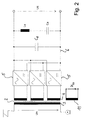
- FIG. 2 The arrangement of a drive unit 1 with three four-quadrant actuators 5 is illustrated in FIG. 2. It designates U n the primary-side voltage of the transformer 2, C z an intermediate circuit capacitor and L s and C s a suction circuit choke or a suction circuit capacitor for damping harmonics in the intermediate circuit 6.
- the voltage applied to the inverters is referred to as U d .
- the four-quadrant actuators 5 are provided with electric valves implemented as GTOs, which are controlled by ignition signals.
- the switching times of the GTOs are usually determined according to the pulse width modulation method (PWM) by the intersections of a carrier signal 9 with a control voltage U st which defines the voltage setpoint.
- the carrier signal 9 can be present, for example, as a triangular or sawtooth voltage and is synchronized with the mains voltage fundamental oscillation 10.
- a phase shift of the carrier signal 9 with respect to the mains voltage fundamental oscillation 10 causes a shift in the switching times of the GTOs due to the relative shift of the signals to one another.
- the four-quadrant actuators 5 of a drive unit 1 are clocked out of phase with one another in order to reduce the harmonics.
- the offset ⁇ of the phase angle with respect to the mains voltage fundamental oscillation 10 is composed for each four-quadrant actuator 5 from a first time-constant component ⁇ 1 and from a second time-variable component ⁇ 2 .
- the cycle time of each four-quadrant actuator 5 is determined in such a way that the entirety of all four-quadrant actuators 5 that are connected to one another can be clocked uniformly over a period.
- all four-quadrant actuators 5 of a train set thus always have the same shift
- the second time-variable part of the offset ⁇ 2 is then determined.
- the method according to the invention provides the time-variable offset ⁇ 2 depending on an instantaneous value of a parameter, such as, for example, the primary current I prim or also the mains power U prim * I prim of a selected drive unit 1, which can also be referred to as a master drive unit to determine the phase angle of the carrier signal 9 with respect to the mains voltage fundamental oscillation 10.
- a parameter such as, for example, the primary current I prim or also the mains power U prim * I prim of a selected drive unit 1, which can also be referred to as a master drive unit to determine the phase angle of the carrier signal 9 with respect to the mains voltage fundamental oscillation 10.
- the master drive unit is assigned to that locomotive that feeds a train busbar.
- the value of the time-variable offset ⁇ 2 of the phase angle is transmitted to all four-quadrant actuators 5 in the train network and added to the time-constant offset ⁇ 1 of each four-quadrant actuator 5. Accordingly, the time-variable part of the offset ⁇ 2 results in a shift in the clock timing of all the converters involved in the train network with respect to the mains voltage fundamental oscillation 10, while the clock timing of the converters remains unchanged relative to one another.
- the offset ⁇ can be determined using various algorithms.
- linear or trigonometric functions such as tangent, cotangent, and exponential functions or the like can also be used.
- the offset ⁇ is preferably determined at regular, sufficiently small intervals, for example in the ms range.
- any other variables for controlling the phase angle offset ⁇ 2 are also conceivable, such as, for example, the control voltage U st of the four-quadrant 5 or external variables such as radio signals or network-side overvoltages.
Landscapes
- Engineering & Computer Science (AREA)
- Power Engineering (AREA)
- Electric Propulsion And Braking For Vehicles (AREA)
- Inverter Devices (AREA)
- Rectifiers (AREA)
Abstract
Description
- Fig. 1
- eine Übersicht der Antriebseinheit eines Triebfahrzeugs, welche mit einem erfindungsgemässen Verfahren gesteuert wird,
- Fig. 2
- ein Schaltbild eines erfindungsgemäss gesteuerten Netzstromrichters mit drei Netzkreisen, und
- Fig. 3
- ein Blockschaltbild, welches eine Ausführungsform des erfindungsgemässen Verfahrens veranschaulicht.
- 1
- Antriebseinheit
- 2
- Transformator
- 3
- Primärwicklung
- 4
- Traktionswicklung
- 5
- Vierquadrantensteller
- 6
- Gleichspannungszwischenkreis
- 7
- Antriebswechselrichter
- 8
- Asynchronmotor
- 9
- Trägersignal
- 10
- Netzspannungsgrundschwingung
- 11
- Zugsammeschienenwicklung
- Ls
- Saugkreisdrossel
- Cs
- Saugkreiskondensator
- Cz
- Zwischenkreiskondensator
- Ud
- Zwischenkreisspannung
- Un
- Netzspannung
- Uprim
- primärseitige Spannung
- Ust
- Steuerspannung
- Uzs
- Zugsammelschienenspannung
- Iprim
- primärseitiger Strom
- ϕ
- Versatz
- ϕ1
- zeitlich konstanter Versatz
- ϕ2
- zeitlich veränderbarer Versatz
Claims (13)
- Verfahren zur Steuerung von Stromrichtern, insbesondere von Vierquadrantenstellern, welche Stromrichter steuerbare Ventile aufweisen und mittels eines auf die Netzspannung synchronisierten Trägersignals und einer Steuerspannung getaktet werden, dadurch gekennzeichnet, dass der Phasenwinkel des Trägersignals (9) zu dem Phasenwinkel der Netzspannungsgrundschwingung (10) um einen Winkel ϕ2 verschoben ist und dass der Versatz (ϕ2) des Phasenwinkeis abhängig von den zeitlich veränderbaren Momentanwerten ausgewählter Kenngrössen bestimmt wird und daher zeitlich variabel ist.
- Verfahren nach Anspruch 1, dadurch gekennzeichnet, dass der Versatz (ϕ2) des Phasenwinkels gemäss einem ausgewählten Algorithmus bestimmt wird.
- Verfahren nach Anspruch 2, dadurch gekennzeichnet, dass der Zusammenhang zwischen der Kenngrösse und dem Versatz (ϕ2) des Phasenwinkels durch eine lineare Gleichung bestimmt werden kann.
- Verfahren nach Anspruch 2, dadurch gekennzeichnet, dass der Zusammenhang zwischen der Kenngrösse und dem Versatz (ϕ2) des Phasenwinkels durch eine trigonometrische Gleichung bestimmt werden kann.
- Verfahren nach einem der Ansprüche 1 bis 4, dadurch gekennzeichnet, dass als Kenngrösse die Netzleistung gewählt wird.
- Verfahren nach Anspruch 5, dadurch gekennzeichnet, dass sich mit steigender Netzleistung der Versatz (ϕ2) des Phasenwinkels des Trägersignals (9) vergrössert.
- Verfahren nach einem der Ansprüche 5 oder 6, dadurch gekennzeichnet, dass der Versatz (ϕ2) des Phasenwinkels des Trägersignals (9) proportional zu der
- Verfahren nach einem der Ansprüche 1 bis 4, dadurch gekennzeichnet, dass als Kenngrösse die Steuerspannung Ust gewählt wird.
- Verfahren nach einem der Ansprüche 1 bis 4, dadurch gekennzeichnet, dass als Kenngrösse externe Signale, wie beispielsweise Funksignale, netzseitige Überspannungen oder dgl. verwendet werden.
- Verfahren nach einem der Ansprüche 1 bis 9, dadurch gekennzeichnet, dass mehrere Stromrichter, insbesondere Vierquadrantensteller (5) vorgesehen sind, welche miteinander in Wirkbeziehung stehen, dadurch gekennzeichnet, dass sich der Versatz (ϕ) des Phasenwinkels des Trägersignals des jeweiligen Stromrichters aus wenigstens einem ersten Anteil (ϕ1) und einem zweiten Anteil (ϕ2) zusammensetzt, wobei der erste Anteil (ϕ1) zeitlich konstant und der zweite Anteil (ϕ2) zeitlich variabel ist.
- Verfahren nach Anspruch 10, dadurch gekennzeichnet, dass der erste Anteil (ϕ1) eine Funktion der Anzahl der Stromrichter ist, derart, dass die miteinander in Wirkverbindung stehenden Stromrichter phasenversetzt getaktet werden, so dass der Phasenwinkel (ϕ1) zwischen jeweils zwei nacheinander getakteten Stromrichtern im wesentlichen konstant ist.
- Verfahren nach Anspruch 11, dadurch gekennzeichnet, dass der Phasenwinkel (ϕ1) zwischen jeweils zwei nacheinander getakteten Stromrichtern maximal ist.
- Verfahren nach einem der Ansprüche 10 bis 12, dadurch gekennzeichnet, dass der zweite, zeitveränderliche Anteil (ϕ2) abhängig von den zeitlich veränderlichen Momentanwerten ausgewählter Kenngrössen bestimmt wird.
Applications Claiming Priority (2)
| Application Number | Priority Date | Filing Date | Title |
|---|---|---|---|
| DE19830655 | 1998-07-09 | ||
| DE1998130655 DE19830655A1 (de) | 1998-07-09 | 1998-07-09 | Leistungsabhängige Pulsmusterverschiebung |
Publications (2)
| Publication Number | Publication Date |
|---|---|
| EP0973247A1 true EP0973247A1 (de) | 2000-01-19 |
| EP0973247B1 EP0973247B1 (de) | 2007-09-12 |
Family
ID=7873433
Family Applications (1)
| Application Number | Title | Priority Date | Filing Date |
|---|---|---|---|
| EP99112480A Expired - Lifetime EP0973247B1 (de) | 1998-07-09 | 1999-07-01 | Leistungsabhängige Pulsmusterverschiebung |
Country Status (2)
| Country | Link |
|---|---|
| EP (1) | EP0973247B1 (de) |
| DE (2) | DE19830655A1 (de) |
Cited By (1)
| Publication number | Priority date | Publication date | Assignee | Title |
|---|---|---|---|---|
| EP2729341B1 (de) | 2011-09-12 | 2017-09-27 | Siemens Aktiengesellschaft | Schienenfahrzeugsverband |
Families Citing this family (2)
| Publication number | Priority date | Publication date | Assignee | Title |
|---|---|---|---|---|
| ES2820542T3 (es) * | 2011-03-16 | 2021-04-21 | Sma Solar Technology Ag | Ondulador acoplado a una red, disposición de onduladores y procedimiento para hacer funcionar una disposición de onduladores |
| JP6232331B2 (ja) * | 2014-04-03 | 2017-11-15 | 株式会社日立製作所 | 駆動システム |
Citations (3)
| Publication number | Priority date | Publication date | Assignee | Title |
|---|---|---|---|---|
| US4190882A (en) * | 1977-05-05 | 1980-02-26 | Hughes Aircraft Company | System for reducing the effects of power supply switching |
| DE4037531A1 (de) * | 1990-11-26 | 1992-02-06 | Asea Brown Boveri | Verfahren zur steuerung von gleichrichtern |
| FR2717014A1 (fr) * | 1994-03-01 | 1995-09-08 | Telemecanique | Système de commande d'un onduleur a MLI. |
Family Cites Families (2)
| Publication number | Priority date | Publication date | Assignee | Title |
|---|---|---|---|---|
| US5041957A (en) * | 1989-12-20 | 1991-08-20 | Sundstrand Corporation | Stepped-waveform inverter with six subinverters |
| JP3236986B2 (ja) * | 1996-01-16 | 2001-12-10 | 株式会社日立製作所 | 電力変換システム |
-
1998
- 1998-07-09 DE DE1998130655 patent/DE19830655A1/de not_active Withdrawn
-
1999
- 1999-07-01 EP EP99112480A patent/EP0973247B1/de not_active Expired - Lifetime
- 1999-07-01 DE DE59914494T patent/DE59914494D1/de not_active Expired - Fee Related
Patent Citations (3)
| Publication number | Priority date | Publication date | Assignee | Title |
|---|---|---|---|---|
| US4190882A (en) * | 1977-05-05 | 1980-02-26 | Hughes Aircraft Company | System for reducing the effects of power supply switching |
| DE4037531A1 (de) * | 1990-11-26 | 1992-02-06 | Asea Brown Boveri | Verfahren zur steuerung von gleichrichtern |
| FR2717014A1 (fr) * | 1994-03-01 | 1995-09-08 | Telemecanique | Système de commande d'un onduleur a MLI. |
Non-Patent Citations (1)
| Title |
|---|
| SAKUTARO NONAKA ET AL: "SINGLE-PHASE COMPOSITE PWM VOLTAGE SOURCE CONVERTER", CONFERENCE RECORD OF THE INDUSTRY APPLICATIONS CONFERENCE IAS ANNUAL MEETING,US,NEW YORK, IEEE, vol. CONF. 29, pages 761-768, XP000512462, ISBN: 0-7803-1994-X * |
Cited By (2)
| Publication number | Priority date | Publication date | Assignee | Title |
|---|---|---|---|---|
| EP2729341B1 (de) | 2011-09-12 | 2017-09-27 | Siemens Aktiengesellschaft | Schienenfahrzeugsverband |
| DE102011082516B4 (de) | 2011-09-12 | 2019-09-05 | Siemens Mobility GmbH | Schienenfahrzeugsverband |
Also Published As
| Publication number | Publication date |
|---|---|
| DE59914494D1 (de) | 2007-10-25 |
| DE19830655A1 (de) | 2000-01-13 |
| EP0973247B1 (de) | 2007-09-12 |
Similar Documents
| Publication | Publication Date | Title |
|---|---|---|
| DE69723629T2 (de) | Vorrichtung und Verfahren für ein Betriebssystem mit Gleichspannungsversorgung mittels eines Umsetzers ausgehend von verschiedenen Gleich- oder Wechselspannungen | |
| EP2611643A2 (de) | Elektrische energieversorgungsanordnung für antriebseinrichtungen von schienenfahrzeugen | |
| DE10128152B4 (de) | Schiffsantriebssystem mit vermindertem Bordnetzklirrfaktor | |
| DE69420665T2 (de) | Steuerungsvorrichtung für Elektrofahrzeuge | |
| DE4435351C1 (de) | Verfahren zur Regelung eines als Netzstromrichter fungierenden Vierquadrantenstellers | |
| EP0973247A1 (de) | Leistungsabhängige Pulsmusterverschiebung | |
| DE3041963C2 (de) | Wechselstromgespeiste Stromrichteranordnung für Fahrzeuge | |
| AT410184B (de) | Antriebseinrichtung für walzgerüste | |
| DE19729479A1 (de) | Pulsweitenmodulationsverfahren für in Serie geschaltete Umrichter | |
| DE102016107614A1 (de) | Wechselrichter und Verfahren zum Erzeugen eines Wechselstroms | |
| EP0782783B1 (de) | Verfahren zur regelung eines als netzstromrichter fungierenden vierquadrantenstellers | |
| EP0170289B1 (de) | Speiseanordnung für wechselstromgespeiste Gleichstromzugantriebe | |
| EP1053588B1 (de) | Verfahren zur erstellung von stellbefehlen für stromrichter | |
| AT397321B (de) | Schaltungsanordnung bei einem gesteuerten stromrichter | |
| WO2008006490A1 (de) | Anordnung und verfahren zum versorgen von verbrauchern in einem schienenfahrzeug | |
| DE102015220736A1 (de) | Schienenfahrzeug-Antriebseinheit | |
| EP0584660A2 (de) | Verfahren und Schaltungsanordnung zur Reduktion von Oberwellen | |
| DE3427825A1 (de) | Gleichrichter | |
| EP1017157B1 (de) | Verfahren zur Regelung eines nichtharmonischen Anteils im Netzstrom eines netzseitigen Stromrichters und Vorrichtung zur Durchführung des Verfahrens | |
| DE102005017747A1 (de) | Antrieb für ein sich längs einer Fahrbahn bewegendes Fahrzeug, insbesondere eine Magnetschwebebahn | |
| WO1991005401A1 (de) | Verfahren und vorrichtung zum regeln und steuern von wechselspannungen ab dem öffentlichen verteilernetz | |
| DE3933524C2 (de) | Verfahren zum Betrieb eines umrichtergespeisten Drehstrommotors, der zwei galvanisch getrennte, elektrisch um 30 DEG versetzte dreiphasige Ständerwicklungen aufweist | |
| WO2024149524A1 (de) | Ac-seitiges aktives gleichtaktfilter für wechselrichter | |
| CH627316A5 (de) | ||
| DE2755309A1 (de) | Umformer |
Legal Events
| Date | Code | Title | Description |
|---|---|---|---|
| PUAI | Public reference made under article 153(3) epc to a published international application that has entered the european phase |
Free format text: ORIGINAL CODE: 0009012 |
|
| AK | Designated contracting states |
Kind code of ref document: A1 Designated state(s): DE FR IT |
|
| AX | Request for extension of the european patent |
Free format text: AL;LT;LV;MK;RO;SI |
|
| RAP1 | Party data changed (applicant data changed or rights of an application transferred) |
Owner name: DAIMLERCHRYSLER AG |
|
| 17P | Request for examination filed |
Effective date: 20000325 |
|
| AKX | Designation fees paid |
Free format text: DE FR IT |
|
| RAP1 | Party data changed (applicant data changed or rights of an application transferred) |
Owner name: DAIMLERCHRYSLER RAIL SYSTEMS GMBH |
|
| RAP1 | Party data changed (applicant data changed or rights of an application transferred) |
Owner name: BOMBARDIER TRANSPORTATION GMBH |
|
| GRAP | Despatch of communication of intention to grant a patent |
Free format text: ORIGINAL CODE: EPIDOSNIGR1 |
|
| GRAS | Grant fee paid |
Free format text: ORIGINAL CODE: EPIDOSNIGR3 |
|
| GRAA | (expected) grant |
Free format text: ORIGINAL CODE: 0009210 |
|
| AK | Designated contracting states |
Kind code of ref document: B1 Designated state(s): DE FR IT |
|
| REF | Corresponds to: |
Ref document number: 59914494 Country of ref document: DE Date of ref document: 20071025 Kind code of ref document: P |
|
| ET | Fr: translation filed | ||
| PLBE | No opposition filed within time limit |
Free format text: ORIGINAL CODE: 0009261 |
|
| STAA | Information on the status of an ep patent application or granted ep patent |
Free format text: STATUS: NO OPPOSITION FILED WITHIN TIME LIMIT |
|
| 26N | No opposition filed |
Effective date: 20080613 |
|
| PGFP | Annual fee paid to national office [announced via postgrant information from national office to epo] |
Ref country code: FR Payment date: 20090721 Year of fee payment: 11 |
|
| PGFP | Annual fee paid to national office [announced via postgrant information from national office to epo] |
Ref country code: DE Payment date: 20090722 Year of fee payment: 11 |
|
| PGFP | Annual fee paid to national office [announced via postgrant information from national office to epo] |
Ref country code: IT Payment date: 20090725 Year of fee payment: 11 |
|
| REG | Reference to a national code |
Ref country code: FR Ref legal event code: ST Effective date: 20110331 |
|
| PG25 | Lapsed in a contracting state [announced via postgrant information from national office to epo] |
Ref country code: DE Free format text: LAPSE BECAUSE OF NON-PAYMENT OF DUE FEES Effective date: 20110201 |
|
| REG | Reference to a national code |
Ref country code: DE Ref legal event code: R119 Ref document number: 59914494 Country of ref document: DE Effective date: 20110201 |
|
| PG25 | Lapsed in a contracting state [announced via postgrant information from national office to epo] |
Ref country code: FR Free format text: LAPSE BECAUSE OF NON-PAYMENT OF DUE FEES Effective date: 20100802 Ref country code: IT Free format text: LAPSE BECAUSE OF NON-PAYMENT OF DUE FEES Effective date: 20100701 |