EP0973274A2 - Satelliten Kommunikationsanordnung mit einer grösseren effektiven Bedeckungsfläsche der Schnittstellenstationen - Google Patents
Satelliten Kommunikationsanordnung mit einer grösseren effektiven Bedeckungsfläsche der Schnittstellenstationen Download PDFInfo
- Publication number
- EP0973274A2 EP0973274A2 EP99304681A EP99304681A EP0973274A2 EP 0973274 A2 EP0973274 A2 EP 0973274A2 EP 99304681 A EP99304681 A EP 99304681A EP 99304681 A EP99304681 A EP 99304681A EP 0973274 A2 EP0973274 A2 EP 0973274A2
- Authority
- EP
- European Patent Office
- Prior art keywords
- gateway
- satellite
- user terminal
- telecommunications network
- terrestrial
- Prior art date
- Legal status (The legal status is an assumption and is not a legal conclusion. Google has not performed a legal analysis and makes no representation as to the accuracy of the status listed.)
- Withdrawn
Links
- 238000004891 communication Methods 0.000 title claims abstract description 41
- 230000008878 coupling Effects 0.000 claims abstract description 33
- 238000010168 coupling process Methods 0.000 claims abstract description 33
- 238000005859 coupling reaction Methods 0.000 claims abstract description 33
- 238000000034 method Methods 0.000 claims abstract description 29
- 230000011664 signaling Effects 0.000 claims description 6
- 230000004044 response Effects 0.000 claims description 4
- 230000001747 exhibiting effect Effects 0.000 claims 1
- 238000012026 site acceptance test Methods 0.000 description 19
- 101710140501 Sulfate adenylyltransferase subunit 2 1 Proteins 0.000 description 9
- 101710173681 Sulfate adenylyltransferase subunit 2 2 Proteins 0.000 description 9
- 238000010586 diagram Methods 0.000 description 9
- 230000007704 transition Effects 0.000 description 7
- 238000012545 processing Methods 0.000 description 6
- 102100040149 Adenylyl-sulfate kinase Human genes 0.000 description 4
- 230000007480 spreading Effects 0.000 description 4
- 230000005540 biological transmission Effects 0.000 description 3
- 238000005562 fading Methods 0.000 description 3
- XDDAORKBJWWYJS-UHFFFAOYSA-N glyphosate Chemical compound OC(=O)CNCP(O)(O)=O XDDAORKBJWWYJS-UHFFFAOYSA-N 0.000 description 3
- 230000000694 effects Effects 0.000 description 2
- 238000013459 approach Methods 0.000 description 1
- 230000008901 benefit Effects 0.000 description 1
- 230000000903 blocking effect Effects 0.000 description 1
- 230000000881 depressing effect Effects 0.000 description 1
- 230000001771 impaired effect Effects 0.000 description 1
- 238000005259 measurement Methods 0.000 description 1
- 230000000116 mitigating effect Effects 0.000 description 1
- 230000008569 process Effects 0.000 description 1
- 230000001172 regenerating effect Effects 0.000 description 1
- 230000001360 synchronised effect Effects 0.000 description 1
Images


Classifications
-
- H—ELECTRICITY
- H04—ELECTRIC COMMUNICATION TECHNIQUE
- H04B—TRANSMISSION
- H04B7/00—Radio transmission systems, i.e. using radiation field
- H04B7/14—Relay systems
- H04B7/15—Active relay systems
- H04B7/185—Space-based or airborne stations; Stations for satellite systems
- H04B7/1853—Satellite systems for providing telephony service to a mobile station, i.e. mobile satellite service
- H04B7/18558—Arrangements for managing communications, i.e. for setting up, maintaining or releasing a call between stations
- H04B7/1856—Arrangements for managing communications, i.e. for setting up, maintaining or releasing a call between stations for call routing
Definitions
- This invention relates generally to satellite-based communications systems and, in particular, to satellite communications systems that employ a constellation of non-geosynchronous orbit (NGSO) satellites, a plurality of user terminals, and a plurality of gateways for interconnecting voice or data calls between individual ones of the user terminals and terrestrial communication networks via one or more satellites of the NGSO constellation.
- NGSO non-geosynchronous orbit
- LEO Low Earth Orbit
- PSTN Public Switched Telephone Network
- Each gateway has a gateway coverage or service area and provides services to those user terminals that reside permanently within the service area, or that reside temporarily (roamers) within the service area.
- the service area is determined by many factors including, satellite footprint, availability, geometry, national borders, etc.
- a call that arrives at the gateway from the PSTN for a given user terminal is connected to the user terminal via one or more satellites.
- a call originated by the user terminal is connected to the PSTN through the gateway and one or more satellites.
- This system employs a Code Division Multiple Access (CDMA) modulation scheme, or other multiple access schemes, and enables the gateway to set up multiple links to and from the user terminal through two or more satellites using two or more gateway antennas which may be directional or omni-directional.
- CDMA Code Division Multiple Access
- This provides satellite diversity, as the user terminal (and gateway) are enabled to coherently combine two or more received signals, thus mitigating the effects of signal blockage and fading.
- U.S. Patent Applications S.N. 08/903,166, filed 7/3/97, and S.N. 08/239,750, filed 5/9/94 generally teach a satellite communications system wherein a gateway (GW) 1 bidirectionally communicates with a user terminal (UT) 3 via one or more NGSO satellites (e.g., SAT 1 and SAT 2).
- GW 1 and SAT 2 may be bent pipe repeaters, or may use on-board processing and may contain regenerative repeaters.
- the gateway 1 is bidirectionally coupled to a terrestrial communications system, such as the Public Switched Telephone Network (PSTN) which can provide either circuit switched or packet switched (e.g., Internet) voice and data access, as well as to a Ground Data Network (GDN) which provides an ability to communicate with a Ground Operations Control Center (GOCC) and other gateways, which are not shown.
- PSTN Public Switched Telephone Network
- GDN Ground Data Network
- the gateway 1 includes typically a plurality of directional antennas, e.g., antennas 1A and 1B, while the user terminal 3 includes, typically, an omni-directional antenna 3A.
- the gateway 1 can provide multiple satellite diversity by routing Code Division Multiple Access (CDMA), or other appropriately modulated signals, forward links through both SAT 1 and SAT 2.
- CDMA Code Division Multiple Access
- Each forward link (FL) has a unique spreading code that enables the link to be separately despread, demodulated and combined in the user terminal 3, or other means of separating the received signals, so that they can be combined, may be used.
- This provides multiple satellite diversity for the user terminal 3, and facilitates overcoming signal blockage and fading conditions that may occur between the user terminal 3 and one or more of the satellites.
- the user terminal 3 may thus include a multi-finger decorrelator, such as a Rake receiver, or some other suitable receiver capable of discriminating the two or more signals. Two or more fingers of the Rake receiver can be used for receiving forward traffic channels from two or more of the satellites, while another finger can be time multiplexed to receive pilot signals transmitted by the gateway 1 through the different satellites.
- the user terminal derives link quality information from the forward links, such as signal strength, and transmits link quality indications (QIs) back to the gateway 1.
- the gateway 1 is enabled to selectively turn links on and off and/or control individual link power for signals transmitted through individual ones of the satellites 1A and 1B.
- a user terminal would be enabled to transition from a first gateway coverage area to a second gateway coverage area, during a call, without dropping the call or requiring that the call be somehow switched from the first gateway to the second gateway.
- some mobile user terminals such as those contained within automobiles, trains and aircraft, will cross political and other boundaries that also happen to define boundaries between adjacent gateway service areas.
- the present invention provides a method for operating a satellite communications system, and a system that operates in accordance with the method.
- the method includes steps of (a) establishing a call connection between a terrestrial telecommunications network and a user terminal via a first gateway and at least one satellite; and (b) while the call connection is established, coupling the user terminal to the terrestrial telecommunications network via a second gateway, in which during a period of time (which could be for the length of the call) the user is connected to both gateways, and at least one further satellite.
- call speech or data information is conveyed between the first gateway and the second gateway over an inter-gateway communications link, in which during a period of time (which could be for the length of the call) the user is connected to both gateways, and data and/or voice traffic is conducted to the user simultaneous via two gateways.
- the step of coupling includes a first step of detecting at the first gateway that the user terminal is capable of communicating with the at least one further satellite that is in view of the second gateway and the user terminal, a second step of negotiating with the second gateway for an assignment of resources to establish a connection with the user terminal, and a third step of bidirectionally coupling the terrestrial telecommunications network to the user terminal through the first gateway, through the second gateway, and through the at least one further satellite using the assigned resources.
- the at least one further satellite could be the at least one original satellite that is fading from the first gateway but not from the second gateway.
- the assigned resources in one instance uses the same resources (frequencies, power and other) that are assigned by the first gateway.
- the user links are established at the second gateway with new and possibly unique resources.
- the step of bidirectionally coupling can include a step of maintaining the call connection through the at least one satellite, or a step of terminating the call connection through the at least one satellite.
- the step of detecting includes steps of generating received signal quality indications in the user terminal for established traffic channels and for pilot channels, and transmitting the quality indications back to the first gateway.
- a further step selectively controls forward link power and on/off states in accordance with the quality indications received from the user terminal.
- the present invention provides a satellite communications system that enables a user terminal to transition, during a call that is connected to a first gateway, from the service area of the first gateway to the service area of a second gateway without dropping the call and without requiring that the call be switched from the first gateway to the second gateway.
- a satellite communications system that enables a user terminal to transition, during a call that is connected to a first gateway, from the service area of the first gateway to the service area of a second gateway without dropping the call and without requiring that the call be switched from the first gateway to the second gateway.
- the call input to a first gateway switch is reconfigured so as to begin at the second gateway.
- Also disclosed is a method for providing a gateway with a larger effective terrestrial coverage area includes steps of (a) providing a first gateway and a second gateway, each gateway having an associated terrestrial coverage area and each gateway being coupled to the same or a different terrestrial telecommunications network. In the case of the same network, the first and second gateways are coupled to the network at two different nodes.
- a next step (b) establishes a call connection between the terrestrial telecommunications network coupled to the first gateway and a user terminal located in the terrestrial coverage area of the first gateway by coupling the user terminal to the first telecommunications network via at least one satellite that is in view of the first gateway and the user terminal; and (c) while the call connection is established, further coupling the user terminal to the terrestrial telecommunications network via the second gateway and at least one further satellite that is in view of the second gateway and the user terminal.
- the call is connected from the network (e.g., PSTN) to the first gateway and remains so for the duration of the call, in which case the call traffic data is conducted from the first gateway to the second gateway by a further network (which could be the ground data network).
- the call traffic is transferred to the second gateway during the call, while still maintaining the user connection to both the first and second gateways.
- This method includes a further step of maintaining the call connection between the first terrestrial telecommunications network coupled to the first gateway and the user terminal after the user terminal moves from the terrestrial coverage area of the first gateway into the terrestrial coverage area of the second gateway.
- the steps of coupling, further coupling, and maintaining each include a step of exchanging call-related data between the first gateway and the second gateway over the inter-gateway communications link.
- the user can be provided with the "best" quality of service of all satellites in view of both gateways.
- the forward and return links between the user terminal and a given gateway are independent, and the gateway diversity could be used on one link and not the other.
- a constellation of communications satellites of most interest to this invention is a Non-Geosynchronous Orbit (NGSO) constellation.
- the NGSO constellation may be a Low Earth Orbit (LEO) or a Medium Earth Orbit (MEO) constellation, or may comprise various High altitude circular or Elliptical Orbits (HEO), or may use orbits such as Loopus, ACE, or Molnya orbits, or any other suitable orbits.
- the NGSO constellation may thus be in any set of orbit configurations, but generally will use inclined circular orbits or polar orbits. However, constellations of elliptical orbit satellites or combinations of elliptical and circular orbits can be used as well.
- the orbit of the NGSO constellation thus need not be inclined but may instead be equatorial, polar, or any other configuration, including sun synchronous.
- the NGSO constellation will be referred to as a LEO constellation using an inclined circular orbit of less than 2000 km, the teachings of this invention are not limited to the use of only this particular type of NGSO constellation.
- the teaching of this invention extends the teachings of the above-referenced U.S. Patent Applications S.N. 08/903,166, filed 7/3/97, and S.N. 08/239,750, filed 5/9/94, to provide multi-gateway diversity for the user terminal 3, as well as controlled links in the multiple satellite diversity case.
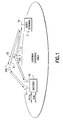
- FIG. 2A-2C there is shown the operation of the satellite communication system in accordance with the teaching of this invention at three instances in time as the user terminal 3 transitions from the coverage area (CA) of a first gateway (GW 1) to the coverage area of a second gateway (GW 2).
- the UT 3 is assumed to be engaged in an active call (voice or data) and may or may not be moving in the direction indicated by the arrow (A).
- the call is connected from a first PSTN (PSTN-1), through the GW 1, and via forward and reverse links made through both SAT 1 and SAT 2.
- PSTN-1 PSTN
- Each forward link contains a traffic channel and a pilot channel, each of which is identifiable by a unique spreading code or some other means of uniquely identifying the signal.
- the UT 3 transmits a traffic channel on the reverse link which is received and relayed to GW 1 by both SAT 1 and SAT 2.
- the UT 3 also transmits link quality indications (QIs) for the received forward traffic links made through SAT 1 (QI-1) and through SAT 2 (QI-2).
- the GW 1 is responsive to the received QIs for selectively turning these links on or off, and/or adjusting the power of each of the forward traffic links, as described in the above-referenced U.S. Patent Applications S.N. 08/903,166, filed 7/3/97, and S.N. 08/239,750. filed 5/9/94.
- the UT 3 begins to receive a pilot channel transmitted from GW 2 through SAT 3. Because of its location, SAT 3 may not be visible to GW 1. Alternatively, SAT 3 may be visible but at a lower elevation angle and thus at lesser quality than other satellites in view of GW 1. Alternatively, for any of a number of reasons the signal from the UT 3 to GW 2 may be better than the signal paths to GW 1. The UT 3 will determine the strength of the pilot channel received through SAT 3 and report same as a QI-3 back to GW 1.
- the GW 1 notes that the UT 3 is receiving the pilot channel energy from GW 2, and will begin comparing the QI- 3 to the QI-1 and QI-2. At some time QI-3 will indicate a better quality link through SAT 3 than, for example, the link made through SAT 1, or alternatively one of the two or more links from GW 1 may be blocked or shadowed. In any case, at some time the QI for GW 2 exceeds some threshold (THRESH) value.
- TRESH threshold
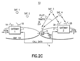
- the GW 1 communicates with GW 2 through an inter-gateway communications link 4 to inform GW 2 of the presence of the UT 3.
- GW 1 and GW 2 then negotiate over the inter-gateway communications link 4 to allocate GW 2 resources for the UT 3. This generally involves an assignment to the UT 3 of at least forward and reverse frequency channels, data rate(s) and CDMA spreading codes.
- the GW 2 resource assignment information is then transmitted from GW 1 to the UT 3 using a predefined signalling protocol, such as one normally used when assigning the UT 3 to a new traffic channel of the GW 1.
- the frequency channel allocation from GW 2 will match the frequency channel allocation used by GW 1.
- the GW 1 begins forwarding the call data (such as vocoded speech or data packets) through the inter-gateway link 4 to GW 2, or by other means, and may then or later terminate the forward and reverse traffic links through SAT 1.
- GW 2 then begins to transmit the call data to the UT 3.
- the UT 3 is operating in a multiple gateway and satellite diversity mode (e.g., SATs 1, 2 and 3 or SATs 2 and 3 and GW 1 and GW 2) and coherently combines the transmissions from these satellites and GWs.
- a multiple gateway and satellite diversity mode e.g., SATs 1, 2 and 3 or SATs 2 and 3 and GW 1 and GW 2
- the reverse link from the UT 3 is made through SAT 3 to GW 2 and then to GW 1 through the inter-gateway communication link 4.
- the UT 3 continues to determine and transmit the quality information for SATs 2 and 3.
- This QI information is received by GW 1 and GW 2, and may be acted on only by GW 1. That is, GW 1 can control the forward link made through SAT 2, and will forward the QI information for SAT 3 back to GW 2 so that GW 2 can control the forward link made through SAT 3.
- each gateway acts independently by comparing the QI information of the link(s) transmitted through itself with the QI information of the link(s) transmitted through other gateways.
- the UT 3 will begin receiving the pilot channel from SAT 4.
- the quality information for the pilot channel received through SAT 4 may then be also relayed back to GW 1.
- the UT 3 has transitioned from the GW 1 coverage area into the GW 2 coverage area.
- the GW 1 also drops the link through SAT 2.
- the ongoing call is still connected from PSTN-1 to GW 1 and through the inter-gateway communication link 4 to GW 2 and then to the UT 3 via SAT 3 and SAT 4.
- the GW 1 can retain overall control of the call, or call control can be shifted to GW 2 (e.g., examining and responding to the QI indicators, performing beam-to-beam and satellite-to-satellite handoffs, etc.)
- Figs. 2A-2C show the case where the single UT 3 is moving from the GW 1 CA to the GW 2 CA. However, it should be realized that at any given time a number of user terminals may be moving in the same manner, and a same or like number may be moving from the GW 2 CA to the GW 1 CA.
- the power control of the various links can be maintained in several ways.
- the UT 3 links are power controlled by the Master Gateway 1, all decisions for GW 2 links are made at GW 1, and all power control signalling is sent via an inter-gateway link.
- the links are power controlled by each participating gateway. In this case information with respect to the link 2 is sent from GW 2 to GW 1 such that, in the case that GW 2 becomes impaired or unusable, communication with another satellite available at GW 1 can be accomplished.
- the user terminal 3 may control its transmit power by responding only to power control commands received from the master gateway (e.g., GW 1), or by receiving power control commands from all participating gateways and increasing its transmitted power only if all participating gateways request an increase.
- the master gateway e.g., GW 1
- the UT 3 When the call is terminated, and if the UT 3 has moved to be within the service area of GW 2, the UT 3 registers with GW 2 in a conventional fashion, the UT 3 home location register (HLR) and any visitor location registers (VLRs) are updated accordingly, and any future incoming or outgoing calls are made through the PSTN-2 that is coupled to GW 2. The same process is followed if the user has transitioned a GW 3 area.
- HLR home location register
- VLRs visitor location registers
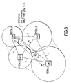
- a network of three gateways (GW 1, GW 2, GW 3) is shown.
- GW 1, GW 2, GW 3 On the ground there is a grid of squares (or any shape such as circles or hexagons) each of which represents a geographic location on the earth. It is possible to place the UT 3 within any of these squares on the grid, and to then couple the UT 3 to one or more gateways by simulating the links while moving the satellites in orbit over the GW's and the grid. By then simulating various blocking profiles, a computer map can be generated, which for any arbitrary quality of availability (i.e.
- a preferred and probable likelihood of the best set of GWs to use can be determined and stored in a map within the GW 1, GW 2 and GW 3 database.
- this is denoted by 1, 2. 3 for use of only GWs 1, 2 and 3, respectively, or by 1/2, 1/3/ or 2/3 which notes that GWs 1 and 2 should be available or GWs 1 and 3 etc.
- this stored map within the GWs can be used to predict needed resources for a UT moving between GWs.
- the call is received at the current registered GW (e.g., GW 1). If the last location of the UT 3 was known to be in an area that is shared between different gateway(s), the registered GW sends a message to the other gateway(s) to page the UT 3. If the registered GW receives the UT 3 response on the reverse link, the registered GW sets up the call. If another GW receives the UT 3 response, a registration is first performed to register the UT 3 so that the new GW can set up the call.
- the current registered GW e.g., GW 1
- the registered GW sends a message to the other gateway(s) to page the UT 3.
- the registered GW receives the UT 3 response on the reverse link, the registered GW sets up the call. If another GW receives the UT 3 response, a registration is first performed to register the UT 3 so that the new GW can set up the call.
- the registered GW For a call from the UT 3, if the registered GW receives the UT 3 call request, the registered GW sets up the call. If another GW receives the UT 3 request, a registration is first performed to register the UT 3 to the new GW, and then the new GW sets up the call.
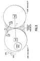
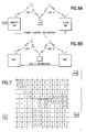
- Fig. 3 depicts an increase in the effective gateway coverage area that is a feature of this invention.
- Each system gateway can be considered to be surrounded by nominally concentric lines such as circles (or any other shape) that bound system availability regions. For example, when located within the inner circle (and not blocked by some RF shielding obstruction such as a tunnel) a user terminal is guaranteed that the satellite communication system is available 100% of the time. When located within the region between the inner circle and the next adjacent circle the system is available 95 % of the time, etc.
- the extent of the availability regions are determined in part by the satellites that can be viewed from the gateway and the user temrinal, in particular those satellites that lie within some predetermined range of elevation angles, such as above 10° from the horizon. While described below in the context of mobile UTs, it should be realized that these teachings apply as well to temporarily stationary UTs as well to fixed UTs.
- the effective gateway coverage region in particular the effective system availability region, is extended since both gateways 1 and 2 can participate, each using one or more satellites that are in view of the particular gateway and the user terminal. and that may not be in view of the other gateway. For example, consider the user terminal 3 that begins a call at position one (P1), then moves to P2, and that then moves to P3 and terminates the call.
- the user terminal would exit the region of 100% system availability when moving to P2, and would exit completely the coverage area of GW 1 when moving to P3.
- the user terminal 3 instead at all times experiences improved system availability due to the extended effective gateway coverage area made possible by the multi-gateway diversity transmission and reception technique of this invention.
- the UT 3 could also remain stationary, either temporarily or permanently, at P2, and then switch to gateway 2, and possibly back again to gateway 1, as a function of satellite availability at the P2 location.
- the shapes of the coverage regions shown in Fig. 3 are exemplary and idealized, and in practice may have other shapes based on, for example, the local terrain and/or the latitude at which the gateways are located.
- Fig. 4 is a simplified block diagram of one embodiment of a gateway showing the origin and termination of the inter-gateway signal paths 4 in accordance with an aspect of this invention. Another, unillustrated, embodiment would switch the call from one gateway to another.
- the gateway such as the GW 1 of Fig. 2, includes a terrestrial telecommunications network interface, such as a PSTN interface block 10 that is bidirectionally coupled to the analog or digital telephone trunk lines of the local PSTN (or to a private telephone network) or to the Internet.
- the PSTN interface 10 which may include a switch or an Internet connection, has outputs connected to a baseband processing block 12A that includes a bank of voice coders (vocoders), and which in turn is connected to a switching block 14A.
- a baseband processing block 12A that includes a bank of voice coders (vocoders)
- vocoders voice coders
- a given vocoder is used to compress a digital representation of a speech signal received from the PSTN, and is bypassed if a data signal is received from the PSTN (e.g., a facsimile signal or packetized data from an Internet server).
- Outputs of the switching block 14A are selectively coupled to a bank of signal modulators 16A where CDMA signal spreading is performed.
- the modulators 16A output modulated signals to an RF transmit circuitry block 18A where the signals are combined and upconverted to a transmission frequency before being applied to a high power amplifier (HPA) 20A.
- the output of the HPA 20A is applied through a duplexer 22 to the gateway directional antenna 24 and is transmitted as a feeder uplink (e.g., C-band or Ku-band) to one of the satellites that is in view of the gateway 1.
- a feeder uplink e.g., C-band or Ku-band
- a feeder downlink from the same satellite is applied through the duplexer 22 to a low noise amplifier (LNA) 20B and then to a receiver RF circuitry block 18B.
- the output of the RF circuitry block 18B is applied to a bank of demodulators 16B, including signal despreaders, and the individual despread signals are then applied through switching block 14B to a baseband processing block 12B that includes a bank of voice decoders (which are bypassed for data signals).
- the recovered speech signals from each of the user terminals serviced by the particular satellite presently pointed at by the directional antenna 24 are then applied to the PSTN interface 10 and connected to the appropriate telephone line, enabling full duplex voice or data calls to occur.
- a gateway controller 26 operates to control the gateway circuitry, to set up signal paths using the switching blocks 12A and 12B, to bypass vocoders as required, and to control the generation and interpretation of signalling messages transmitted to and received from the user terminals.
- This control function includes interpreting the QI signals and controlling the forward link through the satellite accordingly.
- the inter-gateway link 4 originates and terminates at the switching blocks 14A and 14B.
- switching block 14A the baseband voice or data coming from the PSTN for the user terminal is routed to an output of the switching block 14A that is connected to the inter-gateway link 4 and is thus routed on line 4A to the second gateway.
- the data is received at the other gateway switching block 14A and is then applied to one of the modulators as if the input came from the gateway's own block of vocoders.
- the baseband voice or data information is treated in the other gateway as though it were received from the local PSTN (or private network), and is then applied to a selected one of the modulators in the modulator bank 16A.
- the output from the switching block 14B, coming from one of the demodulators 16B, is routed to the inter-gateway link 4 on output line 4D, and demodulated signals from the other gateway are applied to the input to the switching block 14B through input line 4C.
- the baseband voice or data information is treated in the other gateway as though it were received from the antenna 24, and is selectively applied to one of the vocoders (for speech), and other baseband processing is performed as required before the signal is output to the local PSTN (or private network).
- a PSTN speech input for the UT 3 is received, digitized and vocoded. and is then applied on line 4A to the GW 2, where it is received on input line 4B, applied to the input of the switching block 14A. and then used to modulate a carrier before being uplinked to SAT 3.
- a speech signal received from the UT 3 through SAT 3 is demodulated in GW 2 and applied through inter-gateway link line 4D to the GW 1, where it is received on line 4C, and applied to the PSTN via switching block 14B and the baseband processing and voice decoding block 12B.
- switching and inter-gateway link coupling arrangement shown in Fig. 4 is exemplary, and that other configurations could be used.
- a separate switching block could be connected between the output of the modulator bank 16A and the input of the RF circuitry block 18A, and a corresponding switching block could be used between the output of the RF circuitry 18B and the inputs to the demodulator bank 16B, with the inter-gateway link 4 being connected at these points in a manner shown in Fig. 4.
- Diversity combining can be done in one of the gateways, or in both.
- the inter-gateway communications link 4 can convey baseband (digital) call data between the gateways, or it can convey RF call data.
- the gateway controller 26 of GW 2 may examine the incoming QI indicators and respond to only those QI indicators that correspond to the SATs 3 and/or 4, while forwarding the QI indicators for SATS I and/or 2 over the inter-gateway link 4 to the GW 1 for processing.
- one gateway i.e., the Master GW
- each gateway may be responsible for the power control of any UT to which it is coupled, and may thus send power control bits as required to control the UT transmitter power.
- the UT 3 if receiving conflicting power control commands, can operate so as to minimize a possibility of creating interference for other user terminals, such as by selecting the power control command that results in the least transmitted power, or by making a power control adjustment only if commanded to do so by each gateway.
- one of the GWs e.g., GW 1 in Figs. 2A-2C
- the single power-controlling gateway is responsible for generating power control commands that satisfy, if possible, the minimum link requirements for both serving gateways.
- GW 1 may be located in South America, GW 2 in North America, GW 3 in North Africa, and GW 4 in Northern Europe.
- a given UT that is aboard an aircraft may originate a call at position P1, and terminate the call at position P2, all the while being connected to the PSTN-1 at GW 1.
- the same procedure as described in Figs. 2A-2C is performed by the GW 1 for negotiating the allocation of gateway and satellite resources for the UT.
- the inter-gateway links 4 may be made as shown for fully interconnecting the gateways, or each gateway may be connected only to its adjacent gateways (e.g., GW 1 connected only to GWs 2 and 3), with longer links being relayed through intervening gateways (e.g., GW 4 to GW 1 via GW 2 or GW 3).
- the inter-gateway links 4 need not be a separate communication path, but could form a part of the Ground Data Network (GDN) that interconnects all of the gateways to the Ground Operations Control Center (GOCC).
- GDN Ground Data Network
- GOCC Ground Operations Control Center
- the inter-gateway links 4 could be conveyed in whole or in part through the satellites of the communications constellation, or through some other satellite(s) altogether.
- a single PSTN connection is maintained through one of the gateways (the primary gateway), and call information is exchanged over the inter-gateway communication links 4.
- multiple lines 4A-4D are provided at the primary gateway for connecting to the other gateways or can be communicated through the satellite or other satellites.
- the ability to transition between gateway coverage areas as described above may be a value-added feature that is either selected or not selected by a given user, either at the time the user's account and profile is established or on a call-by-call basis.
- the serving gateway may send a message to the UT that is displayed to the user, the message giving the user the option to take advantage of the ability to continue the call even after leaving the gateway's coverage area.
- the appropriate signalling is sent back to the serving gateway for indicating the user's preference.
- a gateway may use the multiple gateway diversity feature for user terminals that are stationary or fixed, or for those that are not transitioning between gateway coverage areas.
- the GW 1 is servicing the UT at position P1 near to the boundary with the GW 2 coverage area, and that an actual or predicted increase in user demand occurs for a region designated as an urban area, or assume that weather conditions or a disaster in the urban area result in more satellite power being required to service the user terminals located there.
- the GW 1 may negotiate with GW 2 to use one or more less heavily loaded satellites that are visible to both GW 2 and the UT, thereby increasing capacity in the GW 1 service area.
- This arrangement may remain in effect for a portion of the on-going call, until the end of the on-going call, or over several consecutive calls, depending on the needs of GW 1 and the ability of GW 2 to accommodate the additional load represented by the UT in the GW 1 coverage area.
- a gateway may also use the multiple gateway diversity feature for UTs beyond the 100% coverage region for the gateway.
Landscapes
- Engineering & Computer Science (AREA)
- Physics & Mathematics (AREA)
- Astronomy & Astrophysics (AREA)
- Aviation & Aerospace Engineering (AREA)
- General Physics & Mathematics (AREA)
- Computer Networks & Wireless Communication (AREA)
- Signal Processing (AREA)
- Radio Relay Systems (AREA)
- Mobile Radio Communication Systems (AREA)
Applications Claiming Priority (2)
| Application Number | Priority Date | Filing Date | Title |
|---|---|---|---|
| US114985 | 1987-10-30 | ||
| US09/114,985 US6661996B1 (en) | 1998-07-14 | 1998-07-14 | Satellite communication system providing multi-gateway diversity to a mobile user terminal |
Publications (2)
| Publication Number | Publication Date |
|---|---|
| EP0973274A2 true EP0973274A2 (de) | 2000-01-19 |
| EP0973274A3 EP0973274A3 (de) | 2001-09-19 |
Family
ID=22358644
Family Applications (1)
| Application Number | Title | Priority Date | Filing Date |
|---|---|---|---|
| EP99304681A Withdrawn EP0973274A3 (de) | 1998-07-14 | 1999-06-16 | Satelliten Kommunikationsanordnung mit einer grösseren effektiven Bedeckungsfläsche der Schnittstellenstationen |
Country Status (5)
| Country | Link |
|---|---|
| US (1) | US6661996B1 (de) |
| EP (1) | EP0973274A3 (de) |
| JP (1) | JP2000078067A (de) |
| CA (1) | CA2274334A1 (de) |
| RU (1) | RU99115466A (de) |
Cited By (2)
| Publication number | Priority date | Publication date | Assignee | Title |
|---|---|---|---|---|
| US6661996B1 (en) * | 1998-07-14 | 2003-12-09 | Globalstar L.P. | Satellite communication system providing multi-gateway diversity to a mobile user terminal |
| US10833759B2 (en) | 2015-07-24 | 2020-11-10 | Qualcomm Incorporated | Wireless communication location reporting and paging |
Families Citing this family (14)
| Publication number | Priority date | Publication date | Assignee | Title |
|---|---|---|---|---|
| SE514049C2 (sv) * | 1999-03-24 | 2000-12-18 | Teracom Ab | Metod för testmottagning av alternativa mottagningsfrekvenser |
| WO2002027974A2 (en) * | 2000-09-28 | 2002-04-04 | Ses Astra S.A. | Satellite communications system |
| US6999434B1 (en) * | 2000-11-28 | 2006-02-14 | Telcordia Technologies, Inc. | Method, system and circuitry for soft handoff in internet protocol-based code division multiple access networks |
| US7505426B2 (en) * | 2000-12-29 | 2009-03-17 | Tropos Networks | Multi-channel mesh network |
| US6909896B2 (en) * | 2001-03-20 | 2005-06-21 | Shiron Satellite Communications (1996) Ltd. | Apparatus and method for two-way data communication via satellite |
| US20020170060A1 (en) * | 2001-05-08 | 2002-11-14 | Lyman Julie F. | Methods and apparatus for transmitting portal content over multiple transmission regions |
| US20040121729A1 (en) * | 2002-10-24 | 2004-06-24 | Chris Herndon | Telecommunications infrastructure linkage method and system |
| US7366125B1 (en) * | 2003-07-24 | 2008-04-29 | Bbn Technologies Corp. | Extensible satellite communication system |
| KR101398908B1 (ko) * | 2007-05-22 | 2014-05-26 | 삼성전자주식회사 | 모바일 아이피를 사용하는 이동 통신 시스템에서 단말의이동성 관리 방법 및 시스템 |
| US8604925B2 (en) * | 2009-10-23 | 2013-12-10 | Globalstar, Inc. | Simplex personal and asset tracker |
| US8676121B1 (en) | 2011-05-31 | 2014-03-18 | Globalstar, Inc. | Method and apparatus for transmitting message from short-range wireless device over a satellite network |
| US9553799B2 (en) * | 2013-11-12 | 2017-01-24 | Twilio, Inc. | System and method for client communication in a distributed telephony network |
| WO2015108997A1 (en) * | 2014-01-14 | 2015-07-23 | Comtech Ef Data Corp. | Seamless antenna handover system and related methods for non-geosynchronous satellites |
| US11387896B1 (en) | 2021-02-01 | 2022-07-12 | Ses S.A. | Satellite terminal antenna pointing arrangement using separate forward and return satellites |
Family Cites Families (60)
| Publication number | Priority date | Publication date | Assignee | Title |
|---|---|---|---|---|
| US3590380A (en) | 1968-02-23 | 1971-06-29 | Philips Corp | Repeater station for information signals containing pseudo-random auxiliary signals |
| GB1360260A (en) | 1971-09-23 | 1974-07-17 | Standard Telephones Cables Ltd | Multilevel pcm system |
| USRE32905F1 (en) | 1980-10-20 | 1992-11-10 | Satellite communications system and apparatus | |
| US4617674A (en) | 1983-07-14 | 1986-10-14 | Rca Corporation | Synchronizing system for spread spectrum transmissions between small earth stations by satellite via an intermediate hop to a large earth station |
| US4639937A (en) | 1983-12-07 | 1987-01-27 | Harris Corporation | HF avalanche relay communication technique |
| US5303286A (en) | 1991-03-29 | 1994-04-12 | Space Systems/Loral, Inc. | Wireless telephone/satellite roaming system |
| US4613990A (en) | 1984-06-25 | 1986-09-23 | At&T Bell Laboratories | Radiotelephone transmission power control |
| US4670885A (en) | 1985-02-26 | 1987-06-02 | Signatron, Inc. | Spread spectrum adaptive antenna interference canceller |
| US4901307A (en) | 1986-10-17 | 1990-02-13 | Qualcomm, Inc. | Spread spectrum multiple access communication system using satellite or terrestrial repeaters |
| CA1293999C (en) | 1987-08-24 | 1992-01-07 | Osamu Ichiyoshi | Earth station capable of effectively using a frequency band of asatellite |
| GB8801008D0 (en) | 1988-01-18 | 1988-02-17 | British Aerospace | Acquisition system for multiple access optical communication system |
| JPH0748674B2 (ja) | 1988-09-02 | 1995-05-24 | クラリオン株式会社 | スペクトラム拡散受信機 |
| US4914699A (en) | 1988-10-11 | 1990-04-03 | Itt Corporation | High frequency anti-jam communication system terminal |
| IL91529A0 (en) | 1988-10-28 | 1990-04-29 | Motorola Inc | Satellite cellular telephone and data communication system |
| WO1990013186A1 (en) | 1989-04-25 | 1990-11-01 | Geostar Corporation | Communication system employing multiple relay satellites operating on common downlink frequency |
| US5172375A (en) * | 1989-06-22 | 1992-12-15 | Nec Corporation | Multiple access satellite communication system for mini-earth station networks |
| US5161248A (en) | 1989-10-02 | 1992-11-03 | Motorola, Inc. | Method of predicting cell-to-cell hand-offs for a satellite cellular communications system |
| US5101501A (en) * | 1989-11-07 | 1992-03-31 | Qualcomm Incorporated | Method and system for providing a soft handoff in communications in a cdma cellular telephone system |
| US5056109A (en) | 1989-11-07 | 1991-10-08 | Qualcomm, Inc. | Method and apparatus for controlling transmission power in a cdma cellular mobile telephone system |
| US5265119A (en) | 1989-11-07 | 1993-11-23 | Qualcomm Incorporated | Method and apparatus for controlling transmission power in a CDMA cellular mobile telephone system |
| US5109390A (en) | 1989-11-07 | 1992-04-28 | Qualcomm Incorporated | Diversity receiver in a cdma cellular telephone system |
| US5010317A (en) | 1989-11-30 | 1991-04-23 | Motorola, Inc. | Satellite based simulcast paging system |
| ES2108042T3 (es) | 1989-12-14 | 1997-12-16 | Motorola Inc | Sistema de telemensajeria con acuse de recibo por satelite. |
| US5073900A (en) | 1990-03-19 | 1991-12-17 | Mallinckrodt Albert J | Integrated cellular communications system |
| US5446756A (en) | 1990-03-19 | 1995-08-29 | Celsat America, Inc. | Integrated cellular communications system |
| US5103459B1 (en) | 1990-06-25 | 1999-07-06 | Qualcomm Inc | System and method for generating signal waveforms in a cdma cellular telephone system |
| US5081703A (en) | 1990-06-27 | 1992-01-14 | Pactel Corporation | Satellite mobile communication system for rural service areas |
| JPH0777361B2 (ja) | 1990-07-04 | 1995-08-16 | クラリオン株式会社 | スペクトラム拡散受信装置 |
| US5129098A (en) | 1990-09-24 | 1992-07-07 | Novatel Communication Ltd. | Radio telephone using received signal strength in controlling transmission power |
| US5216427A (en) | 1990-11-01 | 1993-06-01 | California Institute Of Technology | Land-mobile satellite communication system |
| US5239671A (en) | 1990-11-13 | 1993-08-24 | Pagemart, Inc. | Simulcast satellite paging system with provision for signal interruption |
| US5299226A (en) | 1990-11-16 | 1994-03-29 | Interdigital Technology Corporation | Adaptive power control for a spread spectrum communications system and method |
| US5093840A (en) | 1990-11-16 | 1992-03-03 | Scs Mobilecom, Inc. | Adaptive power control for a spread spectrum transmitter |
| IL100213A (en) | 1990-12-07 | 1995-03-30 | Qualcomm Inc | CDMA microcellular telephone system and distributed antenna system therefor |
| US5204970A (en) | 1991-01-31 | 1993-04-20 | Motorola, Inc. | Communication system capable of adjusting transmit power of a subscriber unit |
| US5433726A (en) | 1991-04-22 | 1995-07-18 | Trw Inc. | Medium-earth-altitude satellite-based cellular telecommunications system |
| US5439190A (en) | 1991-04-22 | 1995-08-08 | Trw Inc. | Medium-earth-altitude satellite-based cellular telecommunications |
| FR2681995B1 (fr) | 1991-10-01 | 1993-12-10 | Alcatel Espace | Procede de basculement du trafic dans un systeme de communications par satellites en orbite basse a destination de terminaux et systeme de communications mettant en óoeuvre un tel procede. |
| US5526404A (en) | 1991-10-10 | 1996-06-11 | Space Systems/Loral, Inc. | Worldwide satellite telephone system and a network coordinating gateway for allocating satellite and terrestrial gateway resources |
| US5267261A (en) * | 1992-03-05 | 1993-11-30 | Qualcomm Incorporated | Mobile station assisted soft handoff in a CDMA cellular communications system |
| US5233626A (en) | 1992-05-11 | 1993-08-03 | Space Systems/Loral Inc. | Repeater diversity spread spectrum communication system |
| US5305349A (en) | 1993-04-29 | 1994-04-19 | Ericsson Ge Mobile Communications Inc. | Quantized coherent rake receiver |
| US5422647A (en) * | 1993-05-07 | 1995-06-06 | Space Systems/Loral, Inc. | Mobile communication satellite payload |
| JP3457357B2 (ja) * | 1993-07-23 | 2003-10-14 | 株式会社日立製作所 | スペクトル拡散通信システム、送信電力制御方法、移動端末装置及び基地局 |
| US5548808A (en) * | 1993-12-08 | 1996-08-20 | Motorola, Inc. | Method for performing a handoff in a communication system |
| US5574968A (en) * | 1994-06-01 | 1996-11-12 | Motorola, Inc. | Satellite cellular communication methods for performing cell-to-cell handoff |
| US5537679A (en) | 1994-08-01 | 1996-07-16 | Motorola, Inc. | Communication network with flexible handoff scheduling for mobile nodes |
| US5619525A (en) | 1995-06-06 | 1997-04-08 | Globalstar L.P. | Closed loop power control for low earth orbit satellite communications system |
| US5592481A (en) | 1995-06-06 | 1997-01-07 | Globalstar L.P. | Multiple satellite repeater capacity loading with multiple spread spectrum gateway antennas |
| US5634190A (en) * | 1995-06-06 | 1997-05-27 | Globalstar L.P. | Low earth orbit communication satellite gateway-to-gateway relay system |
| US5664006A (en) | 1995-06-07 | 1997-09-02 | Globalstar L.P. | Method for accounting for user terminal connection to a satellite communications system |
| FR2735302B1 (fr) * | 1995-06-12 | 1997-07-11 | Alcatel Espace | Systeme de communication par satellites a defilement, station et terminal y inclus |
| US5862480A (en) * | 1995-12-26 | 1999-01-19 | Motorola, Inc. | Method and apparatus for managing service accessibility between differing radio telecommunication networks |
| EP0909523A4 (de) * | 1996-07-10 | 2001-01-17 | American Pcs Communications Ll | Netzübergangseinrichtung |
| US6233456B1 (en) * | 1996-09-27 | 2001-05-15 | Qualcomm Inc. | Method and apparatus for adjacent coverage area handoff in communication systems |
| US5903554A (en) * | 1996-09-27 | 1999-05-11 | Qualcomm Incorporation | Method and apparatus for measuring link quality in a spread spectrum communication system |
| US5896558A (en) | 1996-12-19 | 1999-04-20 | Globalstar L.P. | Interactive fixed and mobile satellite network |
| US5963870A (en) * | 1997-03-26 | 1999-10-05 | Nortel Networks Corporation | Process for switching between IS-95 forward power control and fast forward power control |
| US6058115A (en) * | 1997-08-04 | 2000-05-02 | Motorola, Inc. | Communication method and apparatus utilizing protocol options |
| US6661996B1 (en) * | 1998-07-14 | 2003-12-09 | Globalstar L.P. | Satellite communication system providing multi-gateway diversity to a mobile user terminal |
-
1998
- 1998-07-14 US US09/114,985 patent/US6661996B1/en not_active Expired - Lifetime
-
1999
- 1999-06-11 CA CA002274334A patent/CA2274334A1/en not_active Abandoned
- 1999-06-16 EP EP99304681A patent/EP0973274A3/de not_active Withdrawn
- 1999-07-13 RU RU99115466/09A patent/RU99115466A/ru not_active Application Discontinuation
- 1999-07-14 JP JP11200499A patent/JP2000078067A/ja active Pending
Cited By (2)
| Publication number | Priority date | Publication date | Assignee | Title |
|---|---|---|---|---|
| US6661996B1 (en) * | 1998-07-14 | 2003-12-09 | Globalstar L.P. | Satellite communication system providing multi-gateway diversity to a mobile user terminal |
| US10833759B2 (en) | 2015-07-24 | 2020-11-10 | Qualcomm Incorporated | Wireless communication location reporting and paging |
Also Published As
| Publication number | Publication date |
|---|---|
| RU99115466A (ru) | 2001-05-10 |
| JP2000078067A (ja) | 2000-03-14 |
| EP0973274A3 (de) | 2001-09-19 |
| US6661996B1 (en) | 2003-12-09 |
| CA2274334A1 (en) | 2000-01-14 |
Similar Documents
| Publication | Publication Date | Title |
|---|---|---|
| US6775251B1 (en) | Satellite communication system providing multi-gateway diversity and improved satellite loading | |
| US9345029B2 (en) | Satellite communication system employing a combination of time division multiplexing and non-orthogonal pseudorandom noise codes and time slots | |
| RU2136108C1 (ru) | Загрузка пропускной способности нескольких спутниковых ретрансляторов сигналами с расширенным спектром от нескольких антенн земных станций | |
| US5918157A (en) | Satellite communications system having distributed user assignment and resource assignment with terrestrial gateways | |
| US6067442A (en) | Satellite communications system having distributed user assignment and resource assignment with terrestrial gateways | |
| CA2590268C (en) | Satellite communication system for communicating packet data messages | |
| US5758261A (en) | Low earth orbit communication satellite gateway-to-gateway relay system | |
| US9143361B2 (en) | Satellite communication system employing a combination of time slots and orthogonal codes | |
| US6735440B2 (en) | Low earth orbit distributed gateway communication system | |
| US6661996B1 (en) | Satellite communication system providing multi-gateway diversity to a mobile user terminal | |
| US7711320B2 (en) | Satellite communication system for communicating packet data messages | |
| CA2589369C (en) | Satellite communication system employing a combination of time division multiplexing and non-orthogonal pseudorandom noise codes and time slots | |
| MXPA99008580A (en) | Satellite communications system having distributed user assignment and resource assignment with terrestrial gateways | |
| HK1010434A (en) | Multiple satellite repeater capacity loading with multiple spread spectrum gateway antennas |
Legal Events
| Date | Code | Title | Description |
|---|---|---|---|
| PUAI | Public reference made under article 153(3) epc to a published international application that has entered the european phase |
Free format text: ORIGINAL CODE: 0009012 |
|
| AK | Designated contracting states |
Kind code of ref document: A2 Designated state(s): AT BE CH CY DE DK ES FI FR GB GR IE IT LI LU MC NL PT SE Kind code of ref document: A2 Designated state(s): DE FI FR GB IT SE |
|
| AX | Request for extension of the european patent |
Free format text: AL;LT;LV;MK;RO;SI |
|
| PUAL | Search report despatched |
Free format text: ORIGINAL CODE: 0009013 |
|
| AK | Designated contracting states |
Kind code of ref document: A3 Designated state(s): AT BE CH CY DE DK ES FI FR GB GR IE IT LI LU MC NL PT SE |
|
| AX | Request for extension of the european patent |
Free format text: AL;LT;LV;MK;RO;SI |
|
| AKX | Designation fees paid |
Free format text: DE FI FR GB IT SE |
|
| STAA | Information on the status of an ep patent application or granted ep patent |
Free format text: STATUS: THE APPLICATION IS DEEMED TO BE WITHDRAWN |
|
| 18D | Application deemed to be withdrawn |
Effective date: 20020320 |