EP0973276A2 - Gain equalizer and optical amplifying transmission line - Google Patents
Gain equalizer and optical amplifying transmission line Download PDFInfo
- Publication number
- EP0973276A2 EP0973276A2 EP99113155A EP99113155A EP0973276A2 EP 0973276 A2 EP0973276 A2 EP 0973276A2 EP 99113155 A EP99113155 A EP 99113155A EP 99113155 A EP99113155 A EP 99113155A EP 0973276 A2 EP0973276 A2 EP 0973276A2
- Authority
- EP
- European Patent Office
- Prior art keywords
- optical
- gain equalizer
- gain
- wavelength
- output
- Prior art date
- Legal status (The legal status is an assumption and is not a legal conclusion. Google has not performed a legal analysis and makes no representation as to the accuracy of the status listed.)
- Withdrawn
Links
Images




Classifications
-
- H—ELECTRICITY
- H04—ELECTRIC COMMUNICATION TECHNIQUE
- H04B—TRANSMISSION
- H04B10/00—Transmission systems employing electromagnetic waves other than radio-waves, e.g. infrared, visible or ultraviolet light, or employing corpuscular radiation, e.g. quantum communication
- H04B10/29—Repeaters
- H04B10/291—Repeaters in which processing or amplification is carried out without conversion of the main signal from optical form
- H04B10/293—Signal power control
- H04B10/294—Signal power control in a multiwavelength system, e.g. gain equalisation
- H04B10/2941—Signal power control in a multiwavelength system, e.g. gain equalisation using an equalising unit, e.g. a filter
-
- H—ELECTRICITY
- H01—ELECTRIC ELEMENTS
- H01S—DEVICES USING THE PROCESS OF LIGHT AMPLIFICATION BY STIMULATED EMISSION OF RADIATION [LASER] TO AMPLIFY OR GENERATE LIGHT; DEVICES USING STIMULATED EMISSION OF ELECTROMAGNETIC RADIATION IN WAVE RANGES OTHER THAN OPTICAL
- H01S3/00—Lasers, i.e. devices using stimulated emission of electromagnetic radiation in the infrared, visible or ultraviolet wave range
- H01S3/10—Controlling the intensity, frequency, phase, polarisation or direction of the emitted radiation, e.g. switching, gating, modulating or demodulating
- H01S3/10007—Controlling the intensity, frequency, phase, polarisation or direction of the emitted radiation, e.g. switching, gating, modulating or demodulating in optical amplifiers
- H01S3/10023—Controlling the intensity, frequency, phase, polarisation or direction of the emitted radiation, e.g. switching, gating, modulating or demodulating in optical amplifiers by functional association of additional optical elements, e.g. filters, gratings, reflectors
-
- H—ELECTRICITY
- H04—ELECTRIC COMMUNICATION TECHNIQUE
- H04B—TRANSMISSION
- H04B10/00—Transmission systems employing electromagnetic waves other than radio-waves, e.g. infrared, visible or ultraviolet light, or employing corpuscular radiation, e.g. quantum communication
- H04B10/29—Repeaters
- H04B10/291—Repeaters in which processing or amplification is carried out without conversion of the main signal from optical form
- H04B10/293—Signal power control
- H04B10/294—Signal power control in a multiwavelength system, e.g. gain equalisation
- H04B10/2942—Signal power control in a multiwavelength system, e.g. gain equalisation using automatic gain control [AGC]
Definitions
- This invention relates to a gain equalizer with variable gain characteristics and an optical amplifying transmission line employing the gain equalizer.
- a gain equalizer is generally disposed for compensating inconstancy of gain of an optical amplifier corresponding to a wavelength.
- the equalizer is a passive or fixed element comprising preset constant equalizing characteristics such as a fiber grating and an etalon filter.
- a wavelength dependency of the gain of the system and equalizing characteristics of the gain equalizer should comprise identical forms as far as possible. Accordingly, plural kind of (fixed) gain equalizers having different equalizing characteristics have been widely used so as to cope with the complicated equalizing characteristics.
- gain equalizing characteristics of the system sometimes deviate from desired characteristics.
- several kinds of secondary gain equalizers should be provided in advance and then a specific secondary gain equalizer is selected and connected according to the gain equalizing characteristics obtained after the installation of the system.
- the difference between temperature at ground level and temperature at the bottom of the sea also causes the deterioration of the gain equalizing characteristics. Namely, the temperature difference must be considered in the system design stage. This makes the system design more difficult.
- An object of the present invention is to provide a gain equalizer and an optical amplifying transmission line for solving the foregoing inconveniences.
- Another object of the present invention is to provide a gain equalizer and an optical amplifying transmission line capable of changing equalizing characteristics.
- the gain equalizer according to the invention comprises a first level adjuster having a variable level adjusting amount which level is constant to a wavelength, and a second level adjuster having a level adjusting amount which inclination to the wavelength is variable. Therefore, when levels of the shorter wavelength side and the longer wavelength side differ, the level difference between the wavelengths can be solved without giving any serious change to the output power of the gain equalizer.
- the inclination of the level adjusting amount in relation to the wavelength is changeable from a plus to a minus, or vice versa so as to be applicable to whether a signal level is greater in shorter or longer wavelength.
- Either of the first and second level adjusters can be installed the first.
- the second level adjuster comprises an output power monitor for monitoring the output power of the gain equalizer, and an optical amplifier which pumping power is controlled to maintain the output power of the gain equalizer constantly according to the monitored results of the output power monitor. Consequently, the level adjusting amount, or gain of the optical amplifier can be automatically controlled by the level adjustment at the first level adjuster and thus the adjustment or setting of the gain equalizing amount becomes simpler.
- the gain equalizer further comprises a low-range optical power detector for detecting an optical power of a predetermined low wavelength range from the output power of the gain equalizer, a high-range optical power detector for detecting an optical power of a predetermined high wavelength range from the output power of the gain equalizer, and a controller for controlling the first and second level adjusters according to the detected results of the low-range and high-range optical power detectors.
- the second level adjuster comprises an optical amplifier
- the controller controls the second level adjuster to keep output power of the gain equalizer constantly according to the sum of the detected results of the low-range and high-range optical power detectors.
- the controller further controls the level-adjusting amount of the first level adjuster according to the difference between the respective detected results of the low-range and high-range optical power detectors.
- the first level adjuster comprises for example a variable optical attenuator
- the second level adjuster comprises for example an optical amplifier
- An optical amplifying transmission line employing the foregoing gain equalizer can correspond to changes with time of the gain equalizing characteristics and the detailed design before the installation becomes unnecessary.
- Fig. 1 shows a first schematic block diagram of the invention.
- An optical transmitter 10 outputs an optical signal toward an optical amplifying transmission line 12.
- the optical signal propagates on the optical amplifying transmission line 12 and inputs an optical receiver 14 to get a receiving process.
- the optical signal is obtained by wavelength-division-multiplexing optical signals of a plurality of wavelengths.
- the optical amplifying transmission line 12 the optical signal is propagated on a transmission optical fiber 16, and optically amplified by an optical amplifying repeater 18, and each difference of gain per wavelength is compensated by a gain equalizer.
- the gain equalizer 20 of the embodiment its equalizing characteristics are changeable even after the installation; a detailed description will be given later.
- the gain equalizers 20 are disposed on the output side of the respective amplifying repeaters 18. However, it is also applicable to dispose the single gain equalizer 20 in every several optical amplifying repeaters 18 as shown in Fig. 2.
- the gain equalizer 20 itself, as described later, has gain, it is also possible to connect the transmission optical fiber 16 between the optical amplifying repeater 18 and the gain equalizer 20. That is, the gain equalizer 20 also functions as the optical amplifying repeater 18.
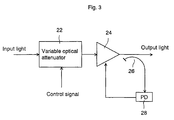
- Fig. 3 shows a schematic block diagram of a first embodiment of a gain equalizer according to the invention.
- Input light enters a variable optical attenuator 22 and therein each wavelength of the input light attenuates at the same attenuation factor.
- the attenuation factor of the variable optical attenuation 22 is constant to the wavelength, and the factor is changeable with an electric signal from the outside of the case or a command signal from a terminal station.
- the variable optical attenuator 22 comprises for example an ND plate, which is available on the market, having different attenuation factors in azimuthal direction, the plate being rotatable at a desired angle using a motor.
- Output light of the variable optical attenuator 22 enters an optical amplifier 24 and optically amplified there.
- the optical amplifier 24 comprises for example an erbium-doped optical amplifying fiber as an optical amplifying medium and thus its gain is not constant in relation to wavelength. Although most output light of the optical amplifier 24 is output toward the outside, a portion of the output light is split by an optical splitter 26 and enters a photodetector 28. The photodetector 28 applies a signal indicating the power of the input light to the optical amplifier 24.
- pumping power of the optical amplifier 24 is feedback-controlled according to the output of the photodetector 28 so that the output power of the optical amplifier 24 becomes constant; namely, the output of the photodetector 28 equalizes to a constant desired value.
- the wavelength characteristics of gain of the optical amplifier 24 depend on pumping power and input power.
- Fig. 4 shows a schematic diagram of wavelength characteristics of gain of the optical amplifier 24 when the pumping power is controlled so that the output power of the optical amplifier 24 becomes constant.
- the horizontal axis shows wavelengths and the vertical axis shows gain.
- a signal wavelength belongs to a 1550 nm band.
- the characteristics 30 are employed so that the gain becomes flat at its signal wavelength band.
- gain of a 1540 nm band increases relative to that of the 1550 band
- gain of a 1560 nm band decreases relative to that of the 1550 band.
- the optical amplifier 24 has characteristics in which the inclination of the gain in relation to the wavelength changes from a minus quantity to a plus quantity in accordance with the input power. The differences among the respective characteristic curves 30, 32 and 34 are relative.
- the above-mentioned characteristics of the optical amplifier 24 are utilized.
- gain of a longer wavelength side decreases compared to that of a shorter wavelength.
- the attenuation factor of the variable optical attenuator 22 is decreased and the input power of the optical amplifier 24 is intentionally increased, the gain of the longer wavelength side increases compared to that of the shorter wavelength side. Consequently, changing the attenuation factor of the variable optical attenuator 22 can control the wavelength dependence of the net gain of the gain equalizer shown in Fig. 3.
- Fig. 5 shows gain wavelength characteristics of the embodiment shown in Fig. 3.
- the horizontal axis shows wavelengths and the vertical axis shows relative gains in relation to gain of a 1556 nm band.
- the attenuation factor of the variable optical attenuator 22 was changed and its characteristics were observed.
- the numeric values from 3.5 dB to 10.5 dB show the gain of the optical amplifier 24. It is understood from Fig. 5 that the inclination of the gain of the optical amplifier 24 in relation to the wavelength changes from a minus quantity to a plus quantity. Also, it is easier to use because the gain change in relation to the wavelength shows straight lines.
- the attenuation factor of the variable optical attenuator 22 should be increased. On the other hand, if the level of the longer wavelength side is lower compared to that of the shorter wavelength side, the attenuation factor of the variable optical attenuator 22 should be decreased.
- variable optical attenuator 22 is disposed on an input stage of the optical amplifier 24.
- variable optical attenuator also can be disposed between the optical amplifier and the optical splitter for monitoring the output power of the optical amplifier.
- Fig. 6 shows a schematic block diagram of the modified embodiment.
- Input light enters an optical amplifier 40 and optically amplified there.
- Output light of the optical amplifier 40 enters a variable optical attenuator 42 and its respective wavelengths attenuate at the same attenuation factor. Although most output light of the variable optical attenuator 42 is output toward the outside, a portion of the output light is split by an optical splitter 44 and enters a photodetector 46.
- the photodetector 46 outputs an electric signal indicating the input optical power.
- the output of the photodetector 46 is applied to the optical amplifier 40 and the pumping power of the optical amplifier 40 is feedback-controlled so that the input power of the photodetector 46 is maintained at a constant desired value.
- an inclination of the net gain to the wavelength also can be controlled either to be plus or minus and the gain equalizing amount can be changed from the outside even after the installation by controlling the attenuation amount of the variable optical attenuator 42 from the outside.
- the attenuation amount of the variable optical attenuator 42 is increased, the input light intensity of the photodetector 46 is decreased and the pumping power of the optical amplifier 40 is increased.
- the gain wavelength characteristics of the optical amplifier 40 shifts from the characteristics 30 to the characteristics 32 in Fig. 4 and the gain of the shorter wavelength side becomes higher that that of the longer wavelength side.
- the gain wavelength characteristics of the optical amplifier 40 shifts from the characteristics 30 to the characteristics 34 in Fig. 4 and the gain of the shorter wavelength side becomes lower than that of the longer wavelength side.
- the gain equalizing characteristics can be perfectly controlled.
- Fig. 7 shows a schematic block diagram of an embodiment in which the attenuation amount of the variable optical attenuator is automatically controlled so that the levels of the respective wavelengths become equivalent one another.
- Input light enters a variable optical attenuator 50 and its each wavelength attenuates at the same attenuation factor.
- the attenuation factor of the variable optical attenuator 50 similarly to the variable optical attenuator 22, is constant to the wavelength, the attenuation factor can be changed freely with an electric signal from the outside or a command signal.
- Output light of the variable optical attenuator 50 enters an optical amplifier, which is the same with the optical amplifier 24, and optically amplified there. Although output light from the optical amplifier 52 is mostly output toward the outside, a portion of the output light is split by an optical splitter 54. Output light from the optical splitter 54 is applied to an optical low-pass filter (LPF) 56 and an optical high-pass filter (HPF) 58.
- LPF optical low-pass filter
- HPF optical high-pass filter
- the optical LPF 56 extracts the lights (such as ⁇ 1) that belongs to the shorter wavelength side from the signal wavelengths ⁇ 1 ⁇ n (on condition that ⁇ 1 ⁇ n).
- the optical HPF 58 extracts the lights (such as ⁇ n) that belongs to the longer wavelength side from the signal wavelengths ⁇ 1 ⁇ n.
- a photodetector 60 converts output light from the optical LPF 56 to an electric signal and a photodetector 62 converts output light from the optical HPF 58 into an electric signal.
- Output of the photodetector 60 indicates the intensity of the light (such as ⁇ 1) that belongs to the shorter wavelength side in the signal wavelengths ⁇ 1 ⁇ n
- output of the photodetector 62 indicates the light (such as ⁇ n) that belongs to the longer wavelength side in the signal wavelengths ⁇ 1 ⁇ n.
- the outputs from the photodetectors 60 and 62 are applied to an operation control circuit 64.
- the operation control circuit 64 operates the sum and the difference of the outputs of the photodetectors 60 and 62.
- the operation control circuit 64 applies the sum of the outputs of the photodetectors 60 and 62 to the optical amplifier 52, and the optical amplifier 52 controls its pumping power so that the output power of the optical amplifier 52 becomes constant.
- a higher level between the longer wavelength side and the shorter wavelength side is clearly determined from the difference of the outputs of the photodetectors 60 and 62. Therefore, to decrease or to increase the attenuation amount of the variable optical attenuator 50 is easily determined.
- the operation control circuit 64 applies the difference of the outputs of the photodetectors 60 and 62 into the variable optical attenuator 50 as an attenuation factor control signal. According to the control signal from the operation control circuit 64, the variable optical attenuator 50 increases the attenuation factor when the level of the longer wavelength side is higher and decreases the attenuation factor when the level of the shorter wavelength side is higher.
- Input light enters an optical amplifier 70 and optically amplified there. Similarly to the optical amplifier 52, gains of the respective wavelengths of the optical amplifier 70 are sometimes almost equivalent and sometimes different one another.
- Output light from the optical amplifier 70 enters a variable optical attenuator 72 and its each wavelength attenuates at the same attenuation factor.
- the attenuation factor of the variable optical attenuator 72 similarly to the variable optical attenuators 22, 42 and 50, is constant to the wavelength and changeable with an electric signal from the outside or a command signal.
- output light from the variable optical attenuator 72 is mostly output toward the outside, a portion of the output light is split in an optical splitter 74.
- Output light of the optical splitter 74 is applied to an optical low-pass filter (LPF) 76 and an optical high-pass filter (HPF) 78.
- the optical LPF 76 similarly to the optical LPF 56, extracts the lights (such as ⁇ 1) of the shorter wavelength side from the signal wavelengths ⁇ 1 ⁇ n
- the optical HPF 78 similarly to the optical HPF 58, extracts the light (such as ⁇ n) of the longer wavelength side from the signal wavelength ⁇ 1 ⁇ n.
- a photodetector 80 converts output light of the optical LPF 76 into an electric signal
- a photodetector 82 converts output light of the optical HPF 78 into an electric signal.
- Output of the photodetector 80 similarly to that of the photodetector 60, indicates the intensity of the light (such as ⁇ 1) at the shorter wavelength side in the signal wavelengths ⁇ 1 ⁇ n
- output of the photodetector 82 similarly to that of the photodetector 62, indicates the intensity of the light (such as ⁇ n) of the longer wavelength side in the signal wavelengths ⁇ 1 ⁇ n.
- the outputs of the photodetectors 80 and 82 are applied to an operation control circuit 84.
- the operation control circuit 84 similarly to the operation control circuit 64, operates the sum and the difference of the outputs of the photodetectors 80 and 82 and applies a sum signal to the optical amplifier 70 and a difference signal to the variable optical attenuator 72.
- the optical amplifier 70 controls its pumping power so that the output power of the optical amplifier 70 becomes constant according to the sum signal from the operation control circuit 84.
- the variable optical attenuator 72 increases the attenuation factor when the level of the longer wavelength side is higher and decreases it when the level of the shorter wavelength side is higher, according to the difference signal from the operation control circuit 84.
- the optical intensity of the single wavelength on both sides of the signal wavelength band is detected, and the pumping power of the optical amplifiers 52, 70 and the attenuation factor of the variable optical attenuators 50, 72 are controlled by using the sum and the difference of the obtained results. It is also applicable to detect the optical intensity of several wavelengths and to control the pumping power of the respective optical amplifiers 52, 70 and the attenuation factors of the variable optical attenuators 50 and 72 using the sum and the difference of the obtained results.
- the optical amplifiers 24, 42, 52 and 70 are used as the elements for changing the inclination of the gain-to-wavelength from a plus to a minus or vice versa according to the input power.
- the elements can be optical attenuators in which the inclination of the attenuation factor to the wavelength can be changed from a plus (or a minus) to a minus (or a plus) according to the input power.
- any element can be used instead of the optical amplifiers 24, 42, 52 and 70 as far as its inclination of a signal level to a wavelength can be changed from a plus (or a minus) to a minus (or a plus).
- variable optical attenuators 22, 42, 50 and 72 any element capable of equally adjusting its level to a wavelength can be used.
- design of a gain equalizer becomes extremely easier since there is no or less need to consider several factors such as an increase of loss of an optical fiber and difference of temperature at a design process.
- a deterioration of gain equalizing characteristics after the installation due to a increase of loss and the like can be remotely or automatically improved and therefore the gain equalizing characteristics can be excellently maintained over a long period of time.
Landscapes
- Physics & Mathematics (AREA)
- Electromagnetism (AREA)
- Engineering & Computer Science (AREA)
- Computer Networks & Wireless Communication (AREA)
- Signal Processing (AREA)
- Plasma & Fusion (AREA)
- Optics & Photonics (AREA)
- Optical Communication System (AREA)
- Lasers (AREA)
- Cable Transmission Systems, Equalization Of Radio And Reduction Of Echo (AREA)
- Control Of Amplification And Gain Control (AREA)
Abstract
Description
Claims (10)
- A gain equalizer comprising:a first level adjuster having a variable level adjusting amount to be constant toward a wavelength; anda second level adjuster having a level adjusting amount in which its inclination toward the wavelength is variable.
- The gain equalizer of the claim 1 wherein the second level adjuster can vary the inclination of the level adjusting amount to the wavelength from one side of a plus and a minus to the other side.
- The gain equalizer of claim 1 or 2 wherein one output of the first level adjuster and the second level adjuster enters the other.
- The gain equalizer of claim 1, 2 or 3 wherein the second level adjuster comprises an output power monitor for monitoring output power of the gain equalizer and an optical amplifier which pumping power is controlled to maintain the output power of the gain equalizer constant according to a monitoring result of the output power monitor.
- The gain equalizer of anyone of the foregoing claims further comprising a low-range optical power detector for detecting an optical power of a predetermined low wavelength range from the output light of the gain equalizer, high-range optical power detector for detecting an optical power of a predetermined high wavelength range from the output light of the gain equalizer, and a controller for controlling the first level adjuster and the second level adjuster according to respective detected results of the low-range optical power detector and the high-range optical power detector.
- The gain equalizer of claim 5 wherein the second level adjuster comprises an optical amplifier and the controller controls the second level adjuster so as to keep the output power of the gain equalizer constant according to the sum of both detected results of the low-range optical power detector and the high-range optical power detector.
- The gain equalizer of claim 5 or 6 wherein the controller controls the level adjusting amount of the first level adjuster according to the difference between the respective detected results of the low-range optical power detector and the high-range optical power detector.
- The gain equalizer of anyone of the foregoing claims wherein the first level adjuster comprises a variable optical attenuator.
- The gain equalizer of anyone of the foregoing claims wherein the second level adjuster comprises an optical amplifier.
- An optical transmission line comprising a gain equalizer according to any one of claims 1 through 9.
Applications Claiming Priority (2)
| Application Number | Priority Date | Filing Date | Title |
|---|---|---|---|
| JP10201422A JP2000031916A (en) | 1998-07-16 | 1998-07-16 | Gain equalizer and optical amplification transmission line |
| JP20142298 | 1998-07-16 |
Publications (2)
| Publication Number | Publication Date |
|---|---|
| EP0973276A2 true EP0973276A2 (en) | 2000-01-19 |
| EP0973276A3 EP0973276A3 (en) | 2001-02-28 |
Family
ID=16440826
Family Applications (1)
| Application Number | Title | Priority Date | Filing Date |
|---|---|---|---|
| EP99113155A Withdrawn EP0973276A3 (en) | 1998-07-16 | 1999-07-07 | Gain equalizer and optical amplifying transmission line |
Country Status (2)
| Country | Link |
|---|---|
| EP (1) | EP0973276A3 (en) |
| JP (1) | JP2000031916A (en) |
Cited By (7)
| Publication number | Priority date | Publication date | Assignee | Title |
|---|---|---|---|---|
| US6333798B1 (en) | 2001-02-13 | 2001-12-25 | Seneca Networks, Inc. | Bidirectional WDM optical communication network |
| EP1427118A1 (en) * | 2002-12-07 | 2004-06-09 | Samsung Electronics Co., Ltd. | Optical fiber amplifier having automatic power control function and automatic power control method |
| EP2434667A4 (en) * | 2009-09-11 | 2012-08-15 | Huawei Tech Co Ltd | RELAY STATION AND METHOD FOR ADJUSTING OPTICAL OUTPUT SIGNALS OF THE RELAY STATION |
| CN105812066A (en) * | 2014-12-31 | 2016-07-27 | 海思光电子有限公司 | Method and device for controlling optical receiver, and optical receiver |
| CN111801903A (en) * | 2018-02-27 | 2020-10-20 | 日本电气株式会社 | Equalizer device, communication system and equalization method |
| CN113632390A (en) * | 2019-03-25 | 2021-11-09 | 日本电气株式会社 | Optical equalizer, method and non-transitory computer readable medium |
| US20230318249A1 (en) * | 2022-03-31 | 2023-10-05 | Huawei Technologies Co., Ltd. | Systems and methods to reduce the power consumption of an optical fiber amplifier |
Families Citing this family (1)
| Publication number | Priority date | Publication date | Assignee | Title |
|---|---|---|---|---|
| JP6485901B2 (en) * | 2015-01-30 | 2019-03-20 | 住友電工デバイス・イノベーション株式会社 | Control method of optical device |
Family Cites Families (1)
| Publication number | Priority date | Publication date | Assignee | Title |
|---|---|---|---|---|
| DE19547603A1 (en) * | 1995-12-20 | 1997-06-26 | Sel Alcatel Ag | Optical amplifier device |
-
1998
- 1998-07-16 JP JP10201422A patent/JP2000031916A/en not_active Withdrawn
-
1999
- 1999-07-07 EP EP99113155A patent/EP0973276A3/en not_active Withdrawn
Cited By (11)
| Publication number | Priority date | Publication date | Assignee | Title |
|---|---|---|---|---|
| US6333798B1 (en) | 2001-02-13 | 2001-12-25 | Seneca Networks, Inc. | Bidirectional WDM optical communication network |
| EP1427118A1 (en) * | 2002-12-07 | 2004-06-09 | Samsung Electronics Co., Ltd. | Optical fiber amplifier having automatic power control function and automatic power control method |
| US7061670B2 (en) | 2002-12-07 | 2006-06-13 | Samsung Electronics Co., Ltd. | Optical fiber amplifier having automatic power control function and automatic power control method |
| EP2434667A4 (en) * | 2009-09-11 | 2012-08-15 | Huawei Tech Co Ltd | RELAY STATION AND METHOD FOR ADJUSTING OPTICAL OUTPUT SIGNALS OF THE RELAY STATION |
| US8867124B2 (en) | 2009-09-11 | 2014-10-21 | Huawei Technologies Co., Ltd. | Relay station and method for adjusting output optical signals of the relay station |
| CN105812066A (en) * | 2014-12-31 | 2016-07-27 | 海思光电子有限公司 | Method and device for controlling optical receiver, and optical receiver |
| CN105812066B (en) * | 2014-12-31 | 2018-07-20 | 海思光电子有限公司 | Control the method and apparatus and photoreceiver of photoreceiver |
| CN111801903A (en) * | 2018-02-27 | 2020-10-20 | 日本电气株式会社 | Equalizer device, communication system and equalization method |
| CN113632390A (en) * | 2019-03-25 | 2021-11-09 | 日本电气株式会社 | Optical equalizer, method and non-transitory computer readable medium |
| EP3952142A4 (en) * | 2019-03-25 | 2022-05-25 | NEC Corporation | Optical equalizer, method, and non-transitory computer-readable medium |
| US20230318249A1 (en) * | 2022-03-31 | 2023-10-05 | Huawei Technologies Co., Ltd. | Systems and methods to reduce the power consumption of an optical fiber amplifier |
Also Published As
| Publication number | Publication date |
|---|---|
| JP2000031916A (en) | 2000-01-28 |
| EP0973276A3 (en) | 2001-02-28 |
Similar Documents
| Publication | Publication Date | Title |
|---|---|---|
| EP1013021B1 (en) | Dynamic optical amplifier | |
| US7715092B2 (en) | Dynamic raman tilt compensation | |
| KR100343346B1 (en) | Optical Fiber Amplifier Having Variable Gain | |
| US6323994B1 (en) | WDM system equalization with EDFA optical amplifiers | |
| US6545799B1 (en) | Method and apparatus for optical system link control | |
| EP0463771A2 (en) | Multi-stage optical fiber amplifier | |
| EP2209231A2 (en) | Gain and signal level adjustments of cascaded optical amplifiers | |
| US6373625B1 (en) | Method, apparatus, and system for optical amplification | |
| US5915052A (en) | Loop status monitor for determining the amplitude of the signal components of a multi-wavelength optical beam | |
| US6377396B1 (en) | Optical amplifiers with variable optical attenuation for use in fiber-optic communications systems | |
| EP0973276A2 (en) | Gain equalizer and optical amplifying transmission line | |
| JP2001057455A (en) | Method, apparatus and system for level equalization | |
| EP1427118B1 (en) | Optical fiber amplifier having automatic power control function and automatic power control method | |
| CA2433486C (en) | Using gain tilt for local compensation of unwanted power gradients | |
| CN111819805A (en) | Variable equalizer and method of controlling the same | |
| WO2003079584A1 (en) | Method and system for optical fiber transmission using raman amplification | |
| EP0933888A2 (en) | Optical gain equalization unit, optical gain equalization method, and optical fiber transmission line | |
| EP1137129A2 (en) | Optical gain equalizer and optical gain equalizing method | |
| US7042632B2 (en) | Raman amplifier | |
| EP1161015A2 (en) | Optical transmission system, its method, and optical amplification transmission line | |
| WO2003079586A1 (en) | Gain-providing optical power equalizer | |
| JP4391645B2 (en) | Optical fiber transmission system with receiving filter with variable bandwidth | |
| US7127173B2 (en) | Method of adjusting power for a wavelength-division multiplexed optical transmission system | |
| WO1999000924A1 (en) | Dynamic optical amplifier | |
| WO1999000925A1 (en) | Method and apparatus for dynamically equalizing gain in an optical network |
Legal Events
| Date | Code | Title | Description |
|---|---|---|---|
| PUAI | Public reference made under article 153(3) epc to a published international application that has entered the european phase |
Free format text: ORIGINAL CODE: 0009012 |
|
| AK | Designated contracting states |
Kind code of ref document: A2 Designated state(s): FR GB |
|
| AX | Request for extension of the european patent |
Free format text: AL;LT;LV;MK;RO;SI |
|
| PUAL | Search report despatched |
Free format text: ORIGINAL CODE: 0009013 |
|
| AK | Designated contracting states |
Kind code of ref document: A3 Designated state(s): AT BE CH CY DE DK ES FI FR GB GR IE IT LI LU MC NL PT SE |
|
| AX | Request for extension of the european patent |
Free format text: AL;LT;LV;MK;RO;SI |
|
| RIC1 | Information provided on ipc code assigned before grant |
Free format text: 7H 04J 14/02 A, 7H 04B 10/17 B |
|
| 17P | Request for examination filed |
Effective date: 20010420 |
|
| AKX | Designation fees paid |
Free format text: AT BE |
|
| RBV | Designated contracting states (corrected) |
Designated state(s): FR GB |
|
| REG | Reference to a national code |
Ref country code: DE Ref legal event code: 8566 |
|
| STAA | Information on the status of an ep patent application or granted ep patent |
Free format text: STATUS: THE APPLICATION HAS BEEN WITHDRAWN |
|
| 18W | Application withdrawn |
Effective date: 20050617 |