EP0973345A2 - Appareil et méthode pour la transmission et la régistration d'appels d'urgence - Google Patents
Appareil et méthode pour la transmission et la régistration d'appels d'urgence Download PDFInfo
- Publication number
- EP0973345A2 EP0973345A2 EP99610040A EP99610040A EP0973345A2 EP 0973345 A2 EP0973345 A2 EP 0973345A2 EP 99610040 A EP99610040 A EP 99610040A EP 99610040 A EP99610040 A EP 99610040A EP 0973345 A2 EP0973345 A2 EP 0973345A2
- Authority
- EP
- European Patent Office
- Prior art keywords
- call
- assistance
- central processor
- calls
- voice message
- Prior art date
- Legal status (The legal status is an assumption and is not a legal conclusion. Google has not performed a legal analysis and makes no representation as to the accuracy of the status listed.)
- Withdrawn
Links
Images


Classifications
-
- H—ELECTRICITY
- H04—ELECTRIC COMMUNICATION TECHNIQUE
- H04W—WIRELESS COMMUNICATION NETWORKS
- H04W84/00—Network topologies
- H04W84/02—Hierarchically pre-organised networks, e.g. paging networks, cellular networks, WLAN [Wireless Local Area Network] or WLL [Wireless Local Loop]
- H04W84/10—Small scale networks; Flat hierarchical networks
- H04W84/14—WLL [Wireless Local Loop]; RLL [Radio Local Loop]
-
- G—PHYSICS
- G01—MEASURING; TESTING
- G01R—MEASURING ELECTRIC VARIABLES; MEASURING MAGNETIC VARIABLES
- G01R31/00—Arrangements for testing electric properties; Arrangements for locating electric faults; Arrangements for electrical testing characterised by what is being tested not provided for elsewhere
- G01R31/28—Testing of electronic circuits, e.g. by signal tracer
- G01R31/302—Contactless testing
- G01R31/303—Contactless testing of integrated circuits
-
- H—ELECTRICITY
- H04—ELECTRIC COMMUNICATION TECHNIQUE
- H04W—WIRELESS COMMUNICATION NETWORKS
- H04W4/00—Services specially adapted for wireless communication networks; Facilities therefor
- H04W4/90—Services for handling of emergency or hazardous situations, e.g. earthquake and tsunami warning systems [ETWS]
-
- H—ELECTRICITY
- H04—ELECTRIC COMMUNICATION TECHNIQUE
- H04W—WIRELESS COMMUNICATION NETWORKS
- H04W76/00—Connection management
- H04W76/50—Connection management for emergency connections
Definitions
- the present invention relates to systems whereby users can make calls for assistance and, more particularly, to a system for transmitting and registering calls for assistance.
- One disadvantage may be that the transmission of the calls for assistance is not sufficiently reliable.
- systems which may provide sufficient reliability of transmission, perhaps through hard wiring of various components in the system may be relatively troublesome to install, particularly into an already operating facility, such as a retail business.
- some systems are disadvantageous in that they do not provide sufficient feedback to the user who makes the call for assistance.
- a person makes a call for assistance he or she is typically in need of attention because of one or more concerns. Since it may take a certain time to provide the desired attention to the person, it is important that the person is promptly and accurately informed about for example the actions taken, and given instructions about what to do next.
- the system has high performance reliability, for example by continuous low battery alert functions and/or continuous monitoring of call stations. It is important that the system can operate in vast localities, for example by using repeaters which are easy to install. It is important that the system may provide for forwarding the calls for assistance, for example, to a pager.
- a system for transmitting and registering calls for assistance includes a plurality of call boxes, a central processor for receiving calls for assistance from the call boxes, and a plurality of portable radios capable of receiving paging messages from the central processor.
- At least one of the call boxes includes a frequency hopping spread spectrum transmitter for transmitting the calls for assistance, an actuator whereby a user can make a call for assistance, a voice message response device for providing a voice message, and a reset switch for resetting the call box.
- the central processor includes a transceiver for transmitting the paging messages, a receiver for receiving the calls for assistance, a memory and a controller.
- the plurality of portable radios may be carried by associates, whereby an associate may be notified of the call for assistance and report to the location.
- the voice message response device in the call box verifies to the user that the call for assistance has been transmitted, and further instructs the user to remain at the call box until assistance arrives.
- a method of registering and transmitting calls for assistance includes providing a call box at a location, transmitting the call for assistance, receiving the call for assistance at a central processor, communicating a first voice message from the call box, and broadcasting a second voice message to at least one of the plurality of portable radios.
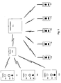
- call boxes 101-103 are shown.
- the call boxes 101-103 may be used to transmit calls for assistance to the central processor 111.
- Each call box includes a push button 105.
- the push button is accessible from outside the call box and a user may use the push button 105 to transmit a call for assistance. It is noted that fewer or more call boxes than the three shown in Figure 1 may be used.
- the call boxes 101-103 further include a light indicator 106 each.
- the light indicator 106 may be a LED.
- the voice message may include an instruction for the user to remain at the location of the particular call box Where the call for assistance was made.
- the call for assistance is transmitted to the central processor 111.
- One or more repeaters 109 may be used to repeat the calls for assistance. Many different well-known repeaters may be used with embodiments of the invention. For example, the 900 MHz repeater manufactured by Inovonics Corporation under the product name FA525 may be used with embodiments of the invention.
- the repeater 109 may allow the calls for assistance to be retransmitted when, for example, the call boxes 101-103 are located far from the central processor 111. Also, the repeater 109 may facilitate retransmission of the calls for assistance when structural features such as walls, etc. Would otherwise obstruct the transmission of the calls for assistance.
- the central processor 111 receives the call for assistance and identifies which one of the call boxes 101-103 transmitted the call for assistance.
- the central processor 111 compiles a suitable paging message based on the received call for assistance.
- the paging message may, for example, include information on the location of the one of the call boxes 101-103 where the call for assistance was made.
- the central processor 111 will transmit the paging message to the portable radios 113-117. Associates which carry the portable radios 113-117, will receive the paging message from the central processor 111, and may report to the location of the call box, and assist the user.
- the portable radios 113-117 are two-way radio transceivers which are capable of transmitting and receiving radio signals including, for example, voice communication and receiving the paging messages from the central processor 111.
- the call boxes 101-103 will now be further described with reference also to Figure 2.
- An exemplary call box is shown schematically in Figure 2.
- the call box is operated by a controller 201.
- Many well-known controllers may be used with embodiments of the invention.
- the controller 201 includes logic and may carry out algorithms suitable for the particular application.
- a user may make a call for assistance using the actuator 203.
- the actuator 203 may include the push button 105 accessible from outside the call box.
- the actuator 203 transmits a signal to the controller 201 indicating that a user is making a call for assistance.
- the controller 201 actuates the frequency hopping spread spectrum transmitter 211, which transmits the call for assistance.
- the transmitter 211 includes all components necessary for transmitting, such as an antenna, etc.
- Different well-known frequency hopping spread spectrum transmitters may be used with embodiments of the invention. For example, 900 MHz transmitters manufactured by Inovonics Corporation under the product names FA210 and FA2l1 may be used.
- the controller 201 actuates the indicator 205, which for example may include the light indicator 106, to provide an indication to the user that the call for assistance has been transmitted.
- the controller 201 also actuates the voice message response device 207 to provide a voice message to the user in response to the call for assistance made by the user.
- the controller 201 obtains the voice message, for example from the memory 209.
- Many different well-known memories may be used with embodiments of the invention
- the memory 209 is capable of storing at least one recorded voice message that may be output to the user through the voice message response device 207.
- the memory 209 may, for example, be a chip memory, in which a voice message can be recorded as is conventionally known.
- the associate may reset the call box using the reset switch 213.
- Different well-known reset switches may be used With embodiments of the invention.
- the controller 201 may, for example, proceed as follows: the indicator 205 is actuated, the voice message response device 207 again transmits the voice message to the user, but the transmitter 211 does not transmit a new call for assistance. It is noted that in other embodiments the controller 201 may carry out other steps, or no steps, in response to a call for assistance made before the call box is reset.
- the call box is powered by the battery 215.
- the battery 215 may be adapted to cause the controller 201 to transmit a low battery alert when the battery 215 runs low.
- the low battery alert may be transmitted through the transmitter 211, and received by the central processor 111, where the situation may be detected by an operator.
- the central processor 111 includes a controller 301.
- the controller 301 includes logic and can carry out algorithms suitable for the application.
- the controller 301 is connected to a frequency hopping spread spectrum receiver 303 for receiving the calls for assistance from call boxes that are present in the system. It is noted that the receiver 303 includes all components necessary for receiving, such as an antenna, etc.
- the controller 301 accesses the storage device 305 in order to compile a paging message.
- the storage device 305 is capable of storing a number of voice recordings, such that each voice recording is individually accessible by the controller 301.
- the storage device 305 is also capable of storing a log of events, such as calls for assistance.
- the storage device 305 may store a start time, finish time, department location and/or other data regarding each particular call for assistance. It is noted that the storage device may consist of one or more units.
- the storage device 305 may consist of a memory for storing a log, and chips for storing voice messages.
- the controller 301 When the controller 301 receives a call for assistance through the transmitter 303, it determines Which call box transmitted the call for assistance. Depending on the information in the call for assistance, the controller 301 accesses the storage device 305 to obtain the suitable voice recordings. The controller 301 will compile a paging message from one or more voice recordings in the storage device 305, and transmit the paging message through the transceiver 307. For example, voice recordings such as "nine”, “aisle”, and "guest assistance needed in” may be compiled by the controller 301 to provide the paging message "guest assistance needed in aisle 9". The paging messages are transmitted by the transceiver 307 to be received, for example, by the portable radios 113-117 that may be carried by associates.
- the transceiver is capable of transmitting and receiving signals to and from the portable radios 113-117. It is noted that the transceiver 307 includes all components necessary for transmitting and receiving, such as antennas, etc. The transceiver 307 may initially verify that a channel is clear prior to transmitting the paging message, by using a receiver function.
- the time device 311 registers a start time.
- the time device 311 registers a finish time.
- the start time and the finish time may be stored for later evaluation.
- the start and finish times may, for example, be stored in the storage device 305.
- the input/output device 309 may be used to output diagnostic information regarding the central processor 111.
- the input/output device 309 may, as another example, be used to input information to the central processor 111. For example, programming steps may be added, changed or deleted in the central processor 111. Furthermore, voice recordings may be brought to the central processor 111 through the input/output device 309.
- the input/output device 309 may include a modem and/or telephone line.
- information stored regarding the start and finish time of one or more calls for assistance may be output to an operator of the system.
- the stored log of start and finish times may for example be evaluated to determine the rate at which assistance arrives after a call for assistance is made.
- the central processor 111 may periodically monitor the call boxes to verify that they still are in operation. For example, the call boxes may periodically transmit a supervisory central message to the central processor 111. If the call box does not transmit its supervisory control message within the expected time period, the central processor 111 will register that the call box is not operating. The central processor 111 may, for example, output the information regarding the call box through the input/output device 309, whereby an operator may notice the situation.
- the central processor 111 may further include a speaker/microphone system 313, connected to the controller 301.
- the speaker/microphone system 313 may for example be used to record paging messages in the central processor 111.
- the operator recording the messages may read the messages into the microphone for recording.
- the speaker may be used for listening to recorded messages.
- Many different microphones and speakers may be used in the speaker/microphone system 313. For example, a conventional speaker and a conventional microphone may be used.
- the central processor 111 further includes a power supply 315.
- a power supply 315 may be a battery or a connection to a power outlet.
- the power supply 315 may optionally be capable of providing backup power if the regular mode power distribution fails, as is conventionally known.
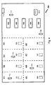
- FIG. 4 A floor plan of a retail business facility 400 is schematically shown.
- the retail business facility 400 includes departments 401-408, characterized for example by containing different categories of merchandise.
- Call boxes 101-108 are located throughout the departments 401-408, such that each department has one call box. It is noted that other configurations of the departments and/or the call boxes are possible.
- the call boxes 101-108 are positioned at places where customers of the retail business facility 400 are likely to need assistance.
- the call boxes 101-108 are typically provided with information signs or labels indicating to the customers that the call box can be used to make a call for assistance.
- Associates of the retail business facility 400 are carrying the portable radios 113-117, which portable radios are illustrated at various locations in the facility 400.
- the central processor 111 is schematically illustrated as a box mounted on a wall of the retail business facility 400. It is noted that the exact location of the central processor 111 may be chosen in consideration of the particular circumstances of the application.
- a number of check-out counters 409 are schematically illustrated toward one end of the retail business facility 400. It is noted that the call boxes 101-108 may be placed at suitable locations throughout the facility 400, for example including the area where the check-out counters 409 are located.
- a call for assistance is made at the call box 104 in department 404.
- the call for assistance is transmitted from the call box 104 to the central processor 111.
- a repeater may repeat the call for assistance between the call box and the central processor.
- the central processor 111 receives the call for assistance, it determines from which call box the call was made, and compiles a paging message, for example including the department number 404 or an equivalent name.
- the call box 104 may, for example, energize a light indicator and provide a voice message to the customer who made the call for assistance.
- the voice message may include instructions to the customer, such as instructions to remain at the location of the call box 104.
- the central processor 111 transmits the paging message to the portable radios 113-117.
- the associates of the facility 400 may hear the paging message through their respective portable radios. If an associate reports to the call box 104, he or she may reset the call box using the reset switch 213. If the call box has not been reset within a predetermined time, the central processor 11 1 may take further steps.
- the central processor 111 may transmit a message to a pager 410.
- Many different well-known pagers may be used with embodiments of the invention. For example, a conventional pager may be used, whereby the central processor 111 may transmit a regular paging phone call to reach the pager 410.
- a manager or equivalent may wear the pager 410 to be informed when a call for assistance has not been reset within the predetermined time.
- the call box may be automatically reset if it has not been manually reset within a time limit.
Landscapes
- Engineering & Computer Science (AREA)
- Computer Hardware Design (AREA)
- Microelectronics & Electronic Packaging (AREA)
- General Engineering & Computer Science (AREA)
- Physics & Mathematics (AREA)
- General Physics & Mathematics (AREA)
- Computer Networks & Wireless Communication (AREA)
- Signal Processing (AREA)
- Testing Of Individual Semiconductor Devices (AREA)
- Tests Of Electronic Circuits (AREA)
- Mobile Radio Communication Systems (AREA)
- Transceivers (AREA)
Applications Claiming Priority (2)
| Application Number | Priority Date | Filing Date | Title |
|---|---|---|---|
| US09/115,998 US6072327A (en) | 1995-05-26 | 1998-07-15 | Method and device of testing semiconductor integrated circuit chip capable of preventing electron-hole pairs |
| US115998 | 1998-07-15 |
Publications (2)
| Publication Number | Publication Date |
|---|---|
| EP0973345A2 true EP0973345A2 (fr) | 2000-01-19 |
| EP0973345A3 EP0973345A3 (fr) | 2001-01-03 |
Family
ID=22364647
Family Applications (1)
| Application Number | Title | Priority Date | Filing Date |
|---|---|---|---|
| EP99610040A Withdrawn EP0973345A3 (fr) | 1998-07-15 | 1999-07-14 | Appareil et méthode pour la transmission et la régistration d'appels d'urgence |
Country Status (2)
| Country | Link |
|---|---|
| US (3) | US6072327A (fr) |
| EP (1) | EP0973345A3 (fr) |
Cited By (1)
| Publication number | Priority date | Publication date | Assignee | Title |
|---|---|---|---|---|
| GB2412209A (en) * | 2004-02-28 | 2005-09-21 | Air Tube Conveyors Ltd | Messaging apparatus method and device |
Families Citing this family (4)
| Publication number | Priority date | Publication date | Assignee | Title |
|---|---|---|---|---|
| JP2001016623A (ja) * | 1999-06-30 | 2001-01-19 | Agilent Technologies Japan Ltd | 撮像素子の試験方法 |
| US6967491B2 (en) * | 2003-07-11 | 2005-11-22 | Credence Systems Corporation | Spatial and temporal selective laser assisted fault localization |
| US7290188B1 (en) * | 2004-08-31 | 2007-10-30 | Advanced Micro Devices, Inc. | Method and apparatus for capturing the internal state of a processor for second and higher order speepaths |
| JP6745196B2 (ja) | 2016-11-04 | 2020-08-26 | 浜松ホトニクス株式会社 | 超音波検査装置 |
Family Cites Families (22)
| Publication number | Priority date | Publication date | Assignee | Title |
|---|---|---|---|---|
| US3805596A (en) * | 1972-02-24 | 1974-04-23 | C Klahr | High resolution ultrasonic imaging scanner |
| US3846565A (en) * | 1972-08-03 | 1974-11-05 | South Bend Range Corp | Method of heating frozen food using sonic or ultrasonic wave energy |
| US3914655A (en) * | 1973-06-28 | 1975-10-21 | Ibm | High brightness ion source |
| CA1272662A (fr) * | 1985-03-26 | 1990-08-14 | Canon Kabushiki Kaisha | Methode et dispositif de controle du debit de fines particules |
| JPS61267336A (ja) * | 1985-05-21 | 1986-11-26 | Matsushita Electric Ind Co Ltd | 半導体装置の検査方法および検査装置 |
| US4724538A (en) * | 1985-09-06 | 1988-02-09 | Comstock Group, Inc. | Emergency roadside telephone communications system |
| US4788711A (en) * | 1985-11-25 | 1988-11-29 | Cellular Communications Corporation | Apparatus and method for a cellular freeway emergency telephone service |
| US4736169A (en) * | 1986-09-29 | 1988-04-05 | Hughes Aircraft Company | Voltage controlled oscillator with frequency sensitivity control |
| US4872212A (en) * | 1987-05-15 | 1989-10-03 | Eip Microwave, Inc. | Microwave main frame |
| US4891584A (en) * | 1988-03-21 | 1990-01-02 | Semitest, Inc. | Apparatus for making surface photovoltage measurements of a semiconductor |
| US4827212A (en) * | 1988-01-20 | 1989-05-02 | Semitest, Inc. | Noninvasive method and apparatus for characterization of semiconductors |
| US5627320A (en) * | 1988-03-23 | 1997-05-06 | Texas Instruments Incorporated | Apparatus and method for automated non-destructive inspection of integrated circuit packages |
| US5046363A (en) * | 1988-03-23 | 1991-09-10 | Texas Instruments Incorporated | Apparatus for rapid non-destructive measurement of die attach quality in packaged integrated circuits |
| US5164040A (en) * | 1989-08-21 | 1992-11-17 | Martin Marietta Energy Systems, Inc. | Method and apparatus for rapidly growing films on substrates using pulsed supersonic jets |
| US5087876A (en) * | 1990-07-16 | 1992-02-11 | Semitest, Inc. | Apparatus and method for making surface photovoltage measurements of a semiconductor |
| JP2765427B2 (ja) * | 1993-04-13 | 1998-06-18 | 日本電気株式会社 | 半導体集積回路内部相互配線の検査方法および装置 |
| US5422498A (en) * | 1993-04-13 | 1995-06-06 | Nec Corporation | Apparatus for diagnosing interconnections of semiconductor integrated circuits |
| GB2283604A (en) * | 1993-11-04 | 1995-05-10 | Michael Robin James | Remote security alarm system |
| JP2861849B2 (ja) * | 1994-08-31 | 1999-02-24 | 日本電気株式会社 | 半導体集積回路チップ上の配線試験方法及びその装置 |
| US5563508A (en) * | 1995-03-31 | 1996-10-08 | Panasonic Technologies | Non-contact resistivity measurement apparatus and method using femtosecond laser pulses to create an electron flow |
| JP2666772B2 (ja) * | 1995-05-26 | 1997-10-22 | 日本電気株式会社 | 超音波加熱を用いた半導体集積回路配線系の検査法および装置 |
| US5631425A (en) * | 1996-03-07 | 1997-05-20 | Integrated Device Technology, Inc. | Method for identifying molding compound using an acoustic microscope |
-
1998
- 1998-07-15 US US09/115,998 patent/US6072327A/en not_active Expired - Fee Related
-
1999
- 1999-04-26 US US09/299,014 patent/US6084423A/en not_active Expired - Fee Related
- 1999-04-26 US US09/299,015 patent/US6137304A/en not_active Expired - Fee Related
- 1999-07-14 EP EP99610040A patent/EP0973345A3/fr not_active Withdrawn
Cited By (1)
| Publication number | Priority date | Publication date | Assignee | Title |
|---|---|---|---|---|
| GB2412209A (en) * | 2004-02-28 | 2005-09-21 | Air Tube Conveyors Ltd | Messaging apparatus method and device |
Also Published As
| Publication number | Publication date |
|---|---|
| EP0973345A3 (fr) | 2001-01-03 |
| US6137304A (en) | 2000-10-24 |
| US6072327A (en) | 2000-06-06 |
| US6084423A (en) | 2000-07-04 |
Similar Documents
| Publication | Publication Date | Title |
|---|---|---|
| US6052052A (en) | Portable alarm system | |
| US7652571B2 (en) | Graphical user interface for emergency apparatus and method for operating same | |
| US4494119A (en) | Distress radiolocation method and system | |
| US5949332A (en) | Fire alarm radio transmitter and receiver set | |
| US6983157B2 (en) | Automatic report control system for reporting arrival at destination or passing point | |
| EP0973345A2 (fr) | Appareil et méthode pour la transmission et la régistration d'appels d'urgence | |
| US6618582B1 (en) | Customer service system with feedback and method for operating | |
| JPH1166477A (ja) | 救助活動支援システム | |
| US8135353B1 (en) | System and method for testing emergency dispatch systems | |
| JPH1166467A (ja) | 警報システム | |
| JP2009094718A (ja) | 無線システム | |
| US11477630B2 (en) | Radio system and radio network gateway thereof | |
| JP2806823B2 (ja) | 緊急通報システム | |
| JP2991428B1 (ja) | 河川水位データの収集通報方法 | |
| JPH0779191A (ja) | 安全管理送受信方法及び安全管理送受信装置 | |
| JPH0775983B2 (ja) | 列車接近警報装置 | |
| JPH10286320A (ja) | 救助活動支援システム | |
| GB2343975A (en) | Security system | |
| JP2845849B2 (ja) | バス接近予告表示解除回路 | |
| JP2001093066A (ja) | 警備システムまたは消防システム | |
| JP2766215B2 (ja) | 生産設備の異常通報システム | |
| JPH02162137A (ja) | 異常通報装置 | |
| RU26671U1 (ru) | Система навигационного сопровождения и безопасности объекта | |
| JPH1178885A (ja) | 多段移動収集システム | |
| JPH08287371A (ja) | 非常用放送システム |
Legal Events
| Date | Code | Title | Description |
|---|---|---|---|
| PUAI | Public reference made under article 153(3) epc to a published international application that has entered the european phase |
Free format text: ORIGINAL CODE: 0009012 |
|
| AK | Designated contracting states |
Kind code of ref document: A2 Designated state(s): AT BE CH CY DE DK ES FI FR GB GR IE IT LI LU MC NL PT SE |
|
| AX | Request for extension of the european patent |
Free format text: AL;LT;LV;MK;RO;SI |
|
| PUAL | Search report despatched |
Free format text: ORIGINAL CODE: 0009013 |
|
| AK | Designated contracting states |
Kind code of ref document: A3 Designated state(s): AT BE CH CY DE DK ES FI FR GB GR IE IT LI LU MC NL PT SE |
|
| AX | Request for extension of the european patent |
Free format text: AL;LT;LV;MK;RO;SI |
|
| 17P | Request for examination filed |
Effective date: 20010703 |
|
| AKX | Designation fees paid |
Free format text: AT BE CH CY DE DK ES FI FR GB GR IE IT LI LU MC NL PT SE |
|
| STAA | Information on the status of an ep patent application or granted ep patent |
Free format text: STATUS: THE APPLICATION IS DEEMED TO BE WITHDRAWN |
|
| 18D | Application deemed to be withdrawn |
Effective date: 20030201 |