EP0973355A2 - Encapsulation en matière plastique pour un transducteur acoustique - Google Patents
Encapsulation en matière plastique pour un transducteur acoustique Download PDFInfo
- Publication number
- EP0973355A2 EP0973355A2 EP99113735A EP99113735A EP0973355A2 EP 0973355 A2 EP0973355 A2 EP 0973355A2 EP 99113735 A EP99113735 A EP 99113735A EP 99113735 A EP99113735 A EP 99113735A EP 0973355 A2 EP0973355 A2 EP 0973355A2
- Authority
- EP
- European Patent Office
- Prior art keywords
- friction element
- plastic
- plastic encapsulation
- acoustic
- sound pressure
- Prior art date
- Legal status (The legal status is an assumption and is not a legal conclusion. Google has not performed a legal analysis and makes no representation as to the accuracy of the status listed.)
- Withdrawn
Links
Images

Classifications
-
- H—ELECTRICITY
- H04—ELECTRIC COMMUNICATION TECHNIQUE
- H04R—LOUDSPEAKERS, MICROPHONES, GRAMOPHONE PICK-UPS OR LIKE ACOUSTIC ELECTROMECHANICAL TRANSDUCERS; ELECTRIC HEARING AIDS; PUBLIC ADDRESS SYSTEMS
- H04R1/00—Details of transducers, loudspeakers or microphones
- H04R1/20—Arrangements for obtaining desired frequency or directional characteristics
- H04R1/22—Arrangements for obtaining desired frequency or directional characteristics for obtaining desired frequency characteristic only
- H04R1/222—Arrangements for obtaining desired frequency or directional characteristics for obtaining desired frequency characteristic only for microphones
-
- H—ELECTRICITY
- H04—ELECTRIC COMMUNICATION TECHNIQUE
- H04M—TELEPHONIC COMMUNICATION
- H04M1/00—Substation equipment, e.g. for use by subscribers
- H04M1/02—Constructional features of telephone sets
- H04M1/03—Constructional features of telephone transmitters or receivers, e.g. telephone hand-sets
-
- H—ELECTRICITY
- H04—ELECTRIC COMMUNICATION TECHNIQUE
- H04R—LOUDSPEAKERS, MICROPHONES, GRAMOPHONE PICK-UPS OR LIKE ACOUSTIC ELECTROMECHANICAL TRANSDUCERS; ELECTRIC HEARING AIDS; PUBLIC ADDRESS SYSTEMS
- H04R1/00—Details of transducers, loudspeakers or microphones
- H04R1/08—Mouthpieces; Microphones; Attachments therefor
-
- H—ELECTRICITY
- H04—ELECTRIC COMMUNICATION TECHNIQUE
- H04R—LOUDSPEAKERS, MICROPHONES, GRAMOPHONE PICK-UPS OR LIKE ACOUSTIC ELECTROMECHANICAL TRANSDUCERS; ELECTRIC HEARING AIDS; PUBLIC ADDRESS SYSTEMS
- H04R1/00—Details of transducers, loudspeakers or microphones
- H04R1/20—Arrangements for obtaining desired frequency or directional characteristics
- H04R1/22—Arrangements for obtaining desired frequency or directional characteristics for obtaining desired frequency characteristic only
- H04R1/225—Arrangements for obtaining desired frequency or directional characteristics for obtaining desired frequency characteristic only for telephonic receivers
Definitions
- the present invention relates to a plastic encapsulation for one acoustic transducer and an encapsulated acoustic transducer for Installation in a housing, in particular a telecommunications device and a method of making such an encapsulated acoustic Converter.
- Acoustic transducers such as microphones, loudspeakers and the like are often pressed or assembled in plastic moldings and then as a unit in a housing of e.g. Telecommunications equipment installed to become.
- the plastic moldings are necessary to make special acoustic performance characteristics of the acoustic transducers, such as sound quality, bass-heavy or higher-heavy frequency response, background noise, etc. to optimize depending on the application.
- the plastic molded parts are usually made of a soft material Made of plastic or rubber and define a recording space for the acoustic transducer, the recording space being dimensioned in such a way that the acoustic transducer fits exactly into the molded plastic part.
- the plastic molded part thus forms an encapsulation for the acoustic Converter.
- Such a plastic encapsulation has one or more sound pressure openings through which the sound enters the acoustic input (s) of the acoustic transducer housed in the plastic encapsulation can reach.
- the number of sound pressure openings and the location of the acoustic transducers in the plastic encapsulation have essential Influence on the acoustic character of the device. With a microphone with "unidirectional" character is only a sound pressure opening provided, and the acoustic input of the transducer is relative far from this sound pressure opening, so that only directed Sound reached the transducer.
- a microphone with "omnidirectional" The acoustic input of the transducer, however, is character close to the sound pressure opening, so that sound from different Directions can reach the acoustic input of the transducer.
- Microphones with a "bidirectional" character have two inputs that are preferably arranged at a 90 ° angle to one another. In order to can eliminate background noise or non-directional sound components by the incident through the sound pressure openings Sound pressures on opposite sides as an acoustic transducer acting membrane are passed so that the undirected Cancel the sound pressure level of the background noise against each other.
- the acoustic performance characteristics of the acoustic transducers but not just because of the type and structure of the plastic encapsulation determined but beyond are on the acoustic transducer even separate acoustically transparent friction elements in the form of textile fabrics or membranes attached to which an acoustic Impedance comes. These friction elements are often porous and therefore permeable to air to achieve the acoustic impedance. That means that the sound pressure reaches due to the air permeability of the friction element as before the acoustic input of the acoustic transducer, but characteristic friction or Sound pressure losses, so that by means of these acoustically transparent friction elements targeted acoustic effects can be achieved.
- That acoustically transparent friction element thus forms in addition to the plastic or.
- Rubber encapsulation another, of the type and structure of the Plastic encapsulation independent damping element.
- the properties of a porous damping element depend in particular on the material thickness. Porosity and nominal pore size. "Acoustically transparent" means in this connection that the sound energy by the friction element is influenced by 0 to 20 dB, depending on the desired characteristic.
- the acoustically transparent friction elements have been immediate applied to the acoustic transducer, for example a microphone, for example glued on.
- the microphone thus prepared was then inserted into the plastic encapsulation, in order then as a unit in a housing, for example a mobile phone, to a suitable one Spot to be attached.
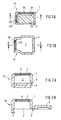
- FIGS. 4a and 4b show a device according to the prior art Technology shown using the example of a bidirectional converter.
- the Plastic encapsulation 10 has two openings 3a, 3b.
- a bidirectional converter used so that the acoustic inputs of which lie behind the openings 3a, 3b come.
- the acoustic inputs are with a self-adhesive membrane 4 covered before inserting the transducer into the plastic encapsulation 10 was applied to the converter.
- a corresponding one Membrane blank 4 with areas 4a and 4b to cover the acoustic inputs against the openings 3a and 3b is in Figure 4b shown as an example.
- Such plastic encapsulations have in the telecommunications sector usually dimensions in the millimeter range and are e.g. about 6 to 8 mm wide or deep and about 5 to 6 mm high.
- the openings can be round or angular, e.g. with a Diameter of 3.5 mm or an edge length of 2 mm x 2.8 mm.
- transducer is problematic in several ways.
- the size of acoustic transducers is particularly in the telecommunications area, as indicated above, on the order of only a few millimeters with a further decreasing tendency.
- a targeted one Attaching the membrane is difficult, complex and corresponding expensive.
- the prepared acoustic Transducers are then inserted into the plastic encapsulation, which, as described above, with their internal dimensions exactly match the external dimensions of the acoustic transducer is matched.
- the object of the present invention is therefore an encapsulated acoustic transducer with acoustically transparent friction element for Installation in a housing, in particular a telecommunications device to create which without much effort and in a reliable manner can be produced.
- connection of the acoustically transparent friction element Surface textile or a membrane, with the plastic encapsulation according to the invention can either be positive or non-positive.
- a snap connection is a good fit, the snap element directly attached to the plastic encapsulation, which is usually is injection molded, can be injected. In this Trap only needs the friction element in front of the sound pressure opening to be placed and pinched by means of a snap connection. On unintentional displacement of the friction element when inserting the acoustic transducer is therefore excluded, and is accordingly the attachment of the friction element compared much less critical by sticking the membrane directly onto the acoustic Converter.
- a plastic encapsulation according to the invention is preferred which is the acoustically transparent friction element during manufacture the plastic encapsulation by "extrusion coating” or “injection molding” is fixed.
- This is also a positive connection of the friction element with the plastic encapsulation.
- injection molding the positive connection is generated in that the plastic material the plastic encapsulation in pores and roughness at least intervenes from partial areas of the textile or membrane surface, while the opposite surface remains free of plastic. It it has been found that this positive connection is complete is sufficient. However, an even more stable connection can be achieved if the friction element is continuous in its edge area from one friction element surface to an opposite one Friction element surface is "overmolded” with plastic material.
- a frictional connection of the friction element with the plastic encapsulation is, for example, by adhesive forces using adhesive possible.
- Plastic encapsulations 10 according to the invention are shown in FIGS. 1 to 3 shown for acoustic transducers that are similar or similar to installation in a housing used for example a telecommunications device become.
- the plastic encapsulations 10 define by their Wall 1 a receiving space 2 for receiving only in Figure 1a exemplary acoustic transducer 20.
- sound pressure openings 3 or 3a and 3b are provided through which the sound from the environment to the acoustic input (s) of the acoustic transducer 20 provided in the receiving space 2 can reach.
- a single sound pressure opening 3 is sufficient, while in the case of a bidirectional one Transducer provided two sound pressure openings 3a and 3b are for the aforementioned reasons and as shown in Figure 1a are preferably aligned at right angles to each other.
- the sound pressure openings are each by an acoustically transparent friction element locked; this is preferably a textile fabric or a membrane that allows the sound pressure to pass, but it does due to the acoustic impedance inherent in the friction element influenced at the same time.
- versions are also conceivable for which an opening is formed without a friction element.
- Embodiments can include the openings in acoustic impedance different (e.g. 100 and 500 ohms) or the same friction elements to be introverted.
- the acoustically transparent friction elements 4 and 4a, 4b are in the in the embodiments shown in Figures 1 and 2 of the Wall 3 enclosed that the wall material continuously from an upper side of the friction element to the correspondingly opposite one Back of the friction element extends. This becomes procedural achieved by the friction element into a shape for Injection molding of the plastic encapsulation 10 is inserted before the Injection molding begins. The friction element 4 is then at Injection molded so that they are firm and form-fitting with the Wall 1 is connected.
- Figure 1 is a plastic encapsulation 10 for a bidirectional Shows transducer 20 in two mutually perpendicular cross sections
- 2 shows a plastic encapsulation 10 for an omnidirectional Also with only one acoustically transparent friction element 4 in cross section.
- the embodiment shown in FIG. 2 is a closure cover 5 above Film hinge 6 molded directly, so that the plastic encapsulation can easily be closed by the cover 5 is snapped behind the nose 7.
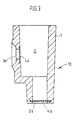
- FIG. 3 shows a further exemplary embodiment of a plastic encapsulation 10 according to the present invention.
- acoustically transparent friction element 4b corresponding to that previously described embodiments according to Figure 1 and Figure 2 with Plastic material of the wall 1 "overmolded” is the friction element 4a only "molded". Also acts in the case of spraying it is a positive connection between the friction element 4a and the wall 1, since the plastic material in the pores and surface roughness of the friction element 4a in the injection molding process penetrates and forms an anchor.
- the acoustically transparent friction element can also be used as an alternative can be fixed in the wall by a snap lock, similar to that in Figure 2 shown in connection with the cap 5 Snap lock, or directly on the surface of the wall 1 can be glued on.
- Porous foils or membranes are therefore particularly suitable made of sintered or unsintered synthetic polymers such as Example polypropylene, polyester, polyamide, polyether, polytetrafluoroethylene (PTFE), polysulfone, ethylene-tetrafluoroethylene copolymer, fluorinated ethylene propylene (FEP) and tetrafluoroethylene / perfluoro (propyl vinyl) ether copolymer (PFA).
- the fluoropolymers mentioned are because of their processing properties, temperature resistance and chemical inertness preferred.
- Particularly preferred become porous membranes made of polytetrafluoroethylene. These can come from contain dark pigments or dyes for aesthetic reasons.
- Porous polytetrafluoroethylene films suitable for use with the invention are suitable, can be prepared by known methods by, for example, stretching or drawing processes, paper manufacturing processes, by procedures in which filler materials in the PTFE resin is stored and then removed to form a leave porous structure, or by powder sintering processes.
- the knots and Fibrils define an internal structure with a three-dimensional one Network of interconnected passages and culverts, which are perpendicular from one surface to the other and laterally from extend one to the other edge through the membrane.
- the porous PTFE film should have a thickness in the range of 0.5 to 1000 ⁇ m, preferably in the range from 5 to 100 ⁇ m, a porosity in the range from 20 to 98%, preferably in the range from 80 to 90%, an air permeability from 0.05 to 30 Gurley seconds, preferably 0.5 to 30 Gurley seconds, and a nominal pore size in the range of 0.05 to Have 50 microns, preferably in the range of 3 to 20 microns.
- a textile fabric can also be used appropriate properties are used.
- a textile fabric fabrics knitted fabrics, fleeces and microfiber textiles are suitable made of synthetic or natural material.
- the friction element on at least one carrier material such as a fleece, a fabric, a knitted fabric, a perforated plate, a grid or non-woven layers made of different plastic materials or organic materials upset.
- a carrier material made of cellulose is preferred.
- the thickness of one preferred carrier material is in the range from 40 to 1000 ⁇ m, preferably 50 to 200 microns.
- the acoustically transparent friction elements usually have a lot thin structures to meet the following characteristics. you Acoustic resistance should be in the range of 0 to 10,000 ohms lie and the sound pressure loss between 0 and 20 dB. As possible for example, laminate is suitable for such applications the applicant available GORE-TEX® laminate EV22209 or EV22210.
- Vulcanizable materials are particularly suitable as the material for the plastic encapsulation Plastics, such as silicones or natural rubber, and thermoplastics, such as polypropylene, polyethylene, Polycarbonates or polyamides and preferably thermoplastic Elastomers such as Santoprene® (available from Montsanto / Italy) or Hytrel® (available from the company DuPont). All of these plastics can be used in the so-called insert Molding use injection molding process, which is the essential The advantage is that the injection molding of the plastic encapsulation and its connection with the acoustically transparent friction elements in one Operation is possible. In particular, the thermoplastic unite Elastomeric properties, in insert molding injection molding to be processed and their elastomer properties preserve.
- the production of the plastic encapsulation according to the invention with an integrated acoustically transparent friction element in insert molding Injection molding is done as follows.
- the friction element will first fixed in an injection mold. It can do that be that the friction element by means of a stamp so against a Wall of the injection molding tool is pressed that now edge areas of the friction element protrude into the injection mold. Then the plastic is injected with the success that the surface of the friction element with the surface of the wall of the pre-sprayed Plastic encapsulation just completes or at least one Side of the friction element remains free of plastic.
- Friction element in such a way to an increase in the injection mold wall pressed that its edge area protrudes laterally beyond this increase, so it is possible to overmold the edge area of the friction element, so that the friction element as shown in Figures 1 and 2, in the Wall 1 is firmly enclosed.
- an opening diameter of e.g. 5 mm is sufficient for a lateral edging of the friction element edge area of about 0.5 mm.
- the production then preferably takes place in accordance with the Sumitomo Electric Industries EP 0 350 813 A2 Limited described using two mobile methods Stamp.
- the acoustic transducer After the plastic encapsulation has been removed from the injection mold can the acoustic transducer easily and without risk of a Detaching the membrane can be used in the plastic encapsulation.
- the plastic encapsulation according to the invention also offers the advantage that in the event that all sound pressure openings are closed with friction elements be the electronic components of the acoustic Converter are fully protected from environmental influences, in particular from dust particles, salts and liquids. This is especially true if the ePTFE membranes are used because they are permeable to air but at the same time waterproof and dustproof.
- the water inlet pressure such friction elements should be over 1 bar.
- the thickness of the membranes was determined with a throat gauge, averaging four different digits.
- Air permeability was determined according to ASTM test procedure D726-84 with a Gurley density meter from W. & L.E. Gurley & Sons determined.
- the water inlet pressure was measured using an ePTFE membrane, which was clamped between two test plates, of which Water pressure is exerted on the membrane via the lower plate can be. Between the top plate and the membrane was a pH paper for the detection of water penetration through the membrane arranged. The pressure was increased in small steps and after each The increase was waited for 10 seconds before the pH paper was examined has been.
- the water inlet pressure is the water pressure at which the pH paper stains due to water breakthrough, the test results be taken from the center of the membrane to influences to avoid damage in the edge area.
Landscapes
- Engineering & Computer Science (AREA)
- Signal Processing (AREA)
- Health & Medical Sciences (AREA)
- Otolaryngology (AREA)
- Physics & Mathematics (AREA)
- Acoustics & Sound (AREA)
- Telephone Set Structure (AREA)
- Obtaining Desirable Characteristics In Audible-Bandwidth Transducers (AREA)
- Audible-Bandwidth Dynamoelectric Transducers Other Than Pickups (AREA)
Applications Claiming Priority (2)
| Application Number | Priority Date | Filing Date | Title |
|---|---|---|---|
| DE19831771 | 1998-07-15 | ||
| DE1998131771 DE19831771C2 (de) | 1998-07-15 | 1998-07-15 | Kunststoffkapselung für einen Wandler und gekapselter akustischer Wandler |
Publications (2)
| Publication Number | Publication Date |
|---|---|
| EP0973355A2 true EP0973355A2 (fr) | 2000-01-19 |
| EP0973355A3 EP0973355A3 (fr) | 2005-02-09 |
Family
ID=7874144
Family Applications (1)
| Application Number | Title | Priority Date | Filing Date |
|---|---|---|---|
| EP99113735A Withdrawn EP0973355A3 (fr) | 1998-07-15 | 1999-07-13 | Encapsulation en matière plastique pour un transducteur acoustique |
Country Status (3)
| Country | Link |
|---|---|
| EP (1) | EP0973355A3 (fr) |
| JP (1) | JP2000151782A (fr) |
| DE (1) | DE19831771C2 (fr) |
Cited By (3)
| Publication number | Priority date | Publication date | Assignee | Title |
|---|---|---|---|---|
| FR2789256A1 (fr) * | 1999-01-28 | 2000-08-04 | Samsung Electro Mech | Microphone et procede de fabrication de celui-ci |
| GB2372397B (en) * | 2001-02-20 | 2004-10-06 | Mitel Corp | Microphone gasket with integrated acoustic resistance |
| CN107277734A (zh) * | 2017-06-21 | 2017-10-20 | 歌尔股份有限公司 | 柔性网注塑模具 |
Families Citing this family (9)
| Publication number | Priority date | Publication date | Assignee | Title |
|---|---|---|---|---|
| DE10043201C1 (de) * | 2000-09-01 | 2002-01-24 | Siemens Audiologische Technik | Elektroakustischer Miniaturwandler |
| DE10053286C2 (de) * | 2000-10-27 | 2002-10-17 | Fhf Funke & Huster Fernsig Gmb | Telefonhörer, insbesondere für Fernsprechapparate an Telefonsäulen |
| JP3908624B2 (ja) * | 2002-07-25 | 2007-04-25 | シチズン電子株式会社 | 電気音響変換器 |
| DE102004027111B4 (de) * | 2004-06-03 | 2008-01-10 | Sennheiser Electronic Gmbh & Co. Kg | Akustischer Wandler |
| JP2006203468A (ja) * | 2005-01-19 | 2006-08-03 | Nippon Denon Kk | 防滴化された単一指向性マイクロホン装置 |
| JP4787947B2 (ja) * | 2005-11-04 | 2011-10-05 | 出光興産株式会社 | 防爆型音響センサ |
| JP4535395B2 (ja) * | 2006-12-19 | 2010-09-01 | 岩崎通信機株式会社 | 送話器 |
| DE102007061310A1 (de) * | 2007-12-19 | 2009-06-25 | Siemens Medical Instruments Pte. Ltd. | Elektroakustischer Miniaturwandler mit Haltemittel zum Einbau in ein Hörgerät |
| JP5080346B2 (ja) * | 2008-04-24 | 2012-11-21 | 株式会社オーディオテクニカ | リボンマイクロホンユニットおよびリボンマイクロホン |
Family Cites Families (8)
| Publication number | Priority date | Publication date | Assignee | Title |
|---|---|---|---|---|
| GB900681A (en) * | 1957-08-05 | 1962-07-11 | Ca Nat Research Council | Improved earphone |
| DE2548566A1 (de) * | 1975-10-30 | 1977-05-05 | Willi Geier | Filmvertonung |
| US4349082A (en) * | 1980-12-22 | 1982-09-14 | Unitron Industries Limited | Acoustical damping element and method of forming same |
| DE3143850A1 (de) * | 1981-11-05 | 1983-06-01 | Peerless-Mb Gmbh Feinmechanik Und Elektronik, 6951 Obrigheim | Elektroakustischer wandler |
| EP0350813A3 (fr) * | 1988-07-09 | 1992-06-17 | Sumitomo Electric Industries, Ltd. | Objet moulé en matière plastique, procédé pour sa fabrication et évent muni de cet objet |
| US5828012A (en) * | 1996-05-31 | 1998-10-27 | W. L. Gore & Associates, Inc. | Protective cover assembly having enhanced acoustical characteristics |
| DE19626792C1 (de) * | 1996-07-03 | 1998-02-26 | Gore W L & Ass Gmbh | Verfahren zur Herstellung eines Verschlußelements in Form eines Kunststoff-Spritzgußteils sowie ein durch dieses Verfahren hergestelltes Verschlußelement |
| US5878147A (en) * | 1996-12-31 | 1999-03-02 | Etymotic Research, Inc. | Directional microphone assembly |
-
1998
- 1998-07-15 DE DE1998131771 patent/DE19831771C2/de not_active Expired - Fee Related
-
1999
- 1999-07-13 EP EP99113735A patent/EP0973355A3/fr not_active Withdrawn
- 1999-07-15 JP JP11201438A patent/JP2000151782A/ja active Pending
Cited By (6)
| Publication number | Priority date | Publication date | Assignee | Title |
|---|---|---|---|---|
| FR2789256A1 (fr) * | 1999-01-28 | 2000-08-04 | Samsung Electro Mech | Microphone et procede de fabrication de celui-ci |
| GB2372397B (en) * | 2001-02-20 | 2004-10-06 | Mitel Corp | Microphone gasket with integrated acoustic resistance |
| US6978033B2 (en) | 2001-02-20 | 2005-12-20 | Mitel Networks Corporation | Microphone gasket with integrated acoustic resistance |
| US7035420B2 (en) | 2001-02-20 | 2006-04-25 | Mitel Knowledge Corporation | Microphone gasket with integrated acoustic resistance |
| CN107277734A (zh) * | 2017-06-21 | 2017-10-20 | 歌尔股份有限公司 | 柔性网注塑模具 |
| CN107277734B (zh) * | 2017-06-21 | 2020-05-29 | 歌尔股份有限公司 | 柔性网注塑模具 |
Also Published As
| Publication number | Publication date |
|---|---|
| DE19831771A1 (de) | 2000-01-27 |
| JP2000151782A (ja) | 2000-05-30 |
| DE19831771C2 (de) | 2001-02-08 |
| EP0973355A3 (fr) | 2005-02-09 |
Similar Documents
| Publication | Publication Date | Title |
|---|---|---|
| DE69714588T2 (de) | Schutzhüllenanordnung mit schallübertragungseigenschaften | |
| DE19831771C2 (de) | Kunststoffkapselung für einen Wandler und gekapselter akustischer Wandler | |
| DE60021079T2 (de) | Akustisch wirksame schutzabdeckung | |
| DE19626792C1 (de) | Verfahren zur Herstellung eines Verschlußelements in Form eines Kunststoff-Spritzgußteils sowie ein durch dieses Verfahren hergestelltes Verschlußelement | |
| DE60022308T2 (de) | Kunststoffgehäuse zum Erreichen von Kompatibilität zwischen der Luftpermeabilität und der Wasserdichtheit, Giessform zur Herstellung eines solchen Gehäuses und Verfahren zum Herstellen eines solchen Gehäuses | |
| DE112017001923T5 (de) | Druckausgleichsaufbau für nichtporöse Akustikmembran | |
| DE102006062044A1 (de) | Druckausgleichselement, insbesondere zum Druckausgleich in einem Gehäuse | |
| DE202014011242U1 (de) | Lüftungselement | |
| DE112017005331B4 (de) | Schalldurchlässige Abdeckung bzw. Schutzabdeckungsanordnung für akustische Einrichtungen | |
| EP1059829B1 (fr) | Haut-parleur avec un joint d'étanchéité monté par l'avant et procédé de fabrication d'un tel haut-parleur | |
| EP3231595A1 (fr) | Composite et procede de fabrication d'un composite pour un composant acoustique | |
| DE112017004598B4 (de) | Lautsprechermembran, Verfahren zu deren Herstellung und diese nutzender Lautsprecher | |
| DE102012219042A1 (de) | Fahrzeugsitzkomponente | |
| DE19715365C2 (de) | Kondensatormikrofon | |
| DE102010041287B4 (de) | Verfahren zum Herstellen einer fluidischen Vorrichtung | |
| DE102016110696A1 (de) | Verfahren zur Herstellung einer Sensorkappe mit einer Membran | |
| DE102018112226A1 (de) | Einlasskanalkomponente für einen Verbrennungsmotor | |
| DE202010010124U1 (de) | Elastomer-Membranventil für den Druckausgleich | |
| DE102005029514B4 (de) | Gehörschutzstöpsel | |
| DE112020005647T5 (de) | Belüftungskomponente | |
| DE112020003803T5 (de) | Belüftungsstruktur | |
| DE102021210581A1 (de) | Zugangselement für Medien an einem Sensor sowie Sensor mit einem derartigen Zugangselement | |
| DE10218936B4 (de) | Verfahren zur Herstellung elektromechanischer Wandler | |
| DE9115939U1 (de) | Schaltgeräteaufnahme und Deckel für ein Druckausgleichselement | |
| DE102010041656A1 (de) | Mikrofonschutz für ein wasserdichtes Hörgerätegehäuse |
Legal Events
| Date | Code | Title | Description |
|---|---|---|---|
| PUAI | Public reference made under article 153(3) epc to a published international application that has entered the european phase |
Free format text: ORIGINAL CODE: 0009012 |
|
| AK | Designated contracting states |
Kind code of ref document: A2 Designated state(s): AT BE CH CY DE DK ES FI FR GB GR IE IT LI LU MC NL PT SE |
|
| AX | Request for extension of the european patent |
Free format text: AL;LT;LV;MK;RO;SI |
|
| PUAL | Search report despatched |
Free format text: ORIGINAL CODE: 0009013 |
|
| AK | Designated contracting states |
Kind code of ref document: A3 Designated state(s): AT BE CH CY DE DK ES FI FR GB GR IE IT LI LU MC NL PT SE |
|
| AX | Request for extension of the european patent |
Extension state: AL LT LV MK RO SI |
|
| AKX | Designation fees paid | ||
| REG | Reference to a national code |
Ref country code: DE Ref legal event code: 8566 |
|
| STAA | Information on the status of an ep patent application or granted ep patent |
Free format text: STATUS: THE APPLICATION IS DEEMED TO BE WITHDRAWN |
|
| 18D | Application deemed to be withdrawn |
Effective date: 20050810 |