EP0973592B1 - Mehrphasen-extraktor mit waschkammer - Google Patents
Mehrphasen-extraktor mit waschkammer Download PDFInfo
- Publication number
- EP0973592B1 EP0973592B1 EP98913737A EP98913737A EP0973592B1 EP 0973592 B1 EP0973592 B1 EP 0973592B1 EP 98913737 A EP98913737 A EP 98913737A EP 98913737 A EP98913737 A EP 98913737A EP 0973592 B1 EP0973592 B1 EP 0973592B1
- Authority
- EP
- European Patent Office
- Prior art keywords
- chamber
- extraction
- extraction chamber
- phase
- washing
- Prior art date
- Legal status (The legal status is an assumption and is not a legal conclusion. Google has not performed a legal analysis and makes no representation as to the accuracy of the status listed.)
- Expired - Lifetime
Links
- 238000000605 extraction Methods 0.000 claims abstract description 63
- 238000005406 washing Methods 0.000 claims abstract description 28
- 238000000926 separation method Methods 0.000 claims description 15
- 239000000126 substance Substances 0.000 description 5
- 239000000463 material Substances 0.000 description 3
- 239000003795 chemical substances by application Substances 0.000 description 2
- 239000007788 liquid Substances 0.000 description 2
- 238000004140 cleaning Methods 0.000 description 1
- 239000003599 detergent Substances 0.000 description 1
- 239000006185 dispersion Substances 0.000 description 1
- 230000000694 effects Effects 0.000 description 1
- 239000004744 fabric Substances 0.000 description 1
- 230000010354 integration Effects 0.000 description 1
- 239000012528 membrane Substances 0.000 description 1
- 238000000034 method Methods 0.000 description 1
- 230000002906 microbiologic effect Effects 0.000 description 1
- 230000007704 transition Effects 0.000 description 1
Images

Classifications
-
- B—PERFORMING OPERATIONS; TRANSPORTING
- B01—PHYSICAL OR CHEMICAL PROCESSES OR APPARATUS IN GENERAL
- B01D—SEPARATION
- B01D11/00—Solvent extraction
- B01D11/04—Solvent extraction of solutions which are liquid
- B01D11/0426—Counter-current multistage extraction towers in a vertical or sloping position
-
- B—PERFORMING OPERATIONS; TRANSPORTING
- B01—PHYSICAL OR CHEMICAL PROCESSES OR APPARATUS IN GENERAL
- B01D—SEPARATION
- B01D11/00—Solvent extraction
- B01D11/02—Solvent extraction of solids
- B01D11/028—Flow sheets
- B01D11/0284—Multistage extraction
-
- B—PERFORMING OPERATIONS; TRANSPORTING
- B01—PHYSICAL OR CHEMICAL PROCESSES OR APPARATUS IN GENERAL
- B01D—SEPARATION
- B01D11/00—Solvent extraction
- B01D2011/002—Counter-current extraction
-
- B—PERFORMING OPERATIONS; TRANSPORTING
- B01—PHYSICAL OR CHEMICAL PROCESSES OR APPARATUS IN GENERAL
- B01D—SEPARATION
- B01D11/00—Solvent extraction
- B01D2011/005—Co-current extraction
Definitions
- the invention is based on a multi-phase extractor with an extraction and a re-extraction chamber, in its upper and lower part through connecting channels are connected, and with distribution devices and connecting pieces for the Supply and discharge of a dispensing phase and a pickup phase are.
- Such a multi-phase extractor can be used in chemical, hydrometallura, microbiological and other industries for separation, extraction, concentration and cleaning of fabrics can be applied.
- three-phase extractor which consists of an extraction filled with the continuous phase (liquid membrane) and re-extraction chamber, closest to the known apparatus.
- the chambers have devices for dispersing the respective phase and are with each other connected by overflows for the circulation of the continuous phase.
- the overflows are designed in the form of connecting channels or tubes which cover the upper and connect the lower part of the chamber to each other.
- the extractor is with nozzle for the supply and discharge of the first and second dispersed phase.
- the first too dispersing phase which is the starting solution or the dispensing phase and the contains the substance to be separated and the second phase to be dispersed or the receiver phase are each in the corresponding chamber by means of a dispersing or Distribution device divided into droplets, which as a swarm of drops through the moving continuous phase. Due to the difference in density of the dispersions in The first and second chambers are circulated through the continuous phase the upper and lower overflows, so that a transition of the extracted substance from a Chamber in the other and from the donor phase into the receiver phase. In the So the first chamber finds an extraction with the continuous phase as Extraction agent and in the second chamber a re-extraction of the separated substance with the receiver phase as the re-extraction agent.
- the object of the invention is to modify the multiphase extractor to open up further applications for which Extraction and re-extraction processes combined with washing processes in one single apparatus can be carried out. In particular, one should Washing of the extractant is made possible.
- the extraction, the Reextraction and the washing chamber equipped with separation zones.
- the upper part of the extraction chamber is immediate connected to the upper part of the re-extraction chamber.
- the upper part of the extraction chamber can be connected directly to the be connected to the lower part of the re-extraction chamber.
- Another alternative is that the lower part of the extraction chamber is directly connected to the lower part of the re-extraction chamber.
- a further development of the invention is characterized in that the extraction chamber and the re-extraction chamber together with the washing chamber Form separation stage and a series of such stages in the form of a cascade in a row are switched.
- washing chambers between the extraction and re-extraction chambers allows the execution of coupled extraction, washing and re-extraction processes in one and the same apparatus.
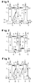
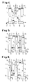
- FIGS. 1-7 schematically show different design variants of the invention Multi-phase extractor for performing coupled extraction, Washing and re-extraction processes are shown.
- the multi-phase extractor basically consists of an extraction chamber 1, a re-extraction chamber 2 and a washing chamber 3, the is arranged between the two chambers 1 and 2.
- 1 and 2 are the 5 and 6, the lower parts of the extraction (1) and Reextraction chamber 2 through the one around the washing chamber 3 Connection tube 5 directly connected to each other.
- the connecting tubes 5 are separation zones 6 in the form of a cross-sectional expansion the chambers 1,2,3 provided. The separation zones that act as separation chambers prevent droplets from being carried along by the circulating stream the continuous phase from one chamber to the other.
- the chamber 1 is a dispensing phase via the nozzle 8, the chamber 2 via the Stub 10 a pickup phase and the chamber 3 via the stub 9 a washing liquid (Washing phase) supplied.
- the washing chamber 3 also has a separation zone 6.
- the lower part of the extraction chamber 1 can the upper (FIG. 1) or lower (FIG. 2) part of the washing chamber 3.
- the extractant is countercurrent with the receiver phase and performed in direct current with the dispensing and washing phase.
- the extractant in countercurrent with the Wash phase and performed in direct current with the transducer and dispenser phase.
- the initial solution (dispenser phase) is the same as for the versions described above abandoned in the extraction chamber 1 via the nozzle 8.
- the too extracting material is through the continuous phase (extractant) extracted.
- the extract phase i.e. the continuous one loaded with the extracted substances Phase
- From the Washing chamber 3 gets the washed extract phase into the re-extraction chamber 2, where the re-extraction takes place through the receiver phase.
- the continuous phase flows through the separation zones 6 into the other chamber and 7 in chambers 1, 2 and 3, which may result in entrainment from the flow Separate droplets from the dispensing, washing or receiving phase.
- the donor, The washing and pick-up phases are separated from the nozzles 11, 13 and 12 Chambers 1, 2 and 3 discharged.
Landscapes
- Chemical & Material Sciences (AREA)
- Chemical Kinetics & Catalysis (AREA)
- Extraction Or Liquid Replacement (AREA)
- Medicines Containing Plant Substances (AREA)
Description
- Fig. 1 - 6
- verschiedene Ausführungsformen von einstufigen Extraktoren
- Fig. 7
- einen mehrstufigen Mehrphasenextraktor
Claims (6)
- Mehrphasen-Extraktor mit einer Extraktions-(1) und einer Reextraktionskammer (2), die in ihrem oberen und unteren Teil durch Verbindungskanale (5) unmittelbar verbunden sind, und mit Verteilungsvorrichtungen (4) sowie Stutzen (8,10,11,12) für die Zuführung und Abrührung einer Abgeberphase und einer Aufnehmerphase ausgestattet sind, dadurch gekennzeichnet, daß die Extraktions- (1) und die Reextraktionskammer (2) über eine dazwischen geschaltete Waschkammer (3) miteinander in Verbindung stehen.
- Mehrphasen-Extraktor nach Anspruch 1, dadurch gekennzeichnet, daß die Extraktions- (1), die Reextraktions-(2). und die Waschkammer (3) mit Separationszonen (6) ausgestattet sind, welche im Bereich der Eingangsöffnungen der Verbindungskanäle (5) angeordnet sind.
- Apparat nach Anspruch 1 - 2, dadurch gekennzeichnet, daß der obere Teil der Extraktionskammer (1) unmittelbar mit dem oberen Teil der Reextraktionskammer (2) verbunden ist.
- Apparat nach Anspruch 1 - 2, dadurch gekennzeichnet, daß der obere Teil der Extraktionskammer (1) unmittelbar mit dem unteren Teil der Reextraktionskammer (2) verbunden ist.
- Apparat nach Anspruch 1 - 2, dadurch gekennzeichnet, daß der untere Teil der Extraktionskammer (1) unmittelbar mit dem unteren Teil der Reextraktionskammer (2) verbunden ist.
- Apparat nach Anspruch 1 - 5, dadurch gekennzeichnet, daß die Extraktionskammer (1) und die Reextraktionskammer (2) zusammen mit der Waschkammer (3) eine Trennstufe bilden und eine Reihe solcher Trennstufen hintereinander geschaltet sind.
Applications Claiming Priority (3)
| Application Number | Priority Date | Filing Date | Title |
|---|---|---|---|
| DE19714579 | 1997-04-09 | ||
| DE19714579A DE19714579A1 (de) | 1997-04-09 | 1997-04-09 | Mehrphasen-Extraktor mit Waschkammer |
| PCT/EP1998/001812 WO1998045014A1 (de) | 1997-04-09 | 1998-03-27 | Mehrphasen-extraktor mit waschkammer |
Publications (2)
| Publication Number | Publication Date |
|---|---|
| EP0973592A1 EP0973592A1 (de) | 2000-01-26 |
| EP0973592B1 true EP0973592B1 (de) | 2002-08-07 |
Family
ID=7825859
Family Applications (1)
| Application Number | Title | Priority Date | Filing Date |
|---|---|---|---|
| EP98913737A Expired - Lifetime EP0973592B1 (de) | 1997-04-09 | 1998-03-27 | Mehrphasen-extraktor mit waschkammer |
Country Status (11)
| Country | Link |
|---|---|
| US (1) | US6454103B1 (de) |
| EP (1) | EP0973592B1 (de) |
| JP (1) | JP2001518831A (de) |
| CN (1) | CN1142810C (de) |
| AT (1) | ATE221796T1 (de) |
| CA (1) | CA2286176A1 (de) |
| DE (2) | DE19714579A1 (de) |
| DK (1) | DK0973592T3 (de) |
| ES (1) | ES2180158T3 (de) |
| RU (1) | RU2203123C2 (de) |
| WO (1) | WO1998045014A1 (de) |
Families Citing this family (5)
| Publication number | Priority date | Publication date | Assignee | Title |
|---|---|---|---|---|
| RU2342969C2 (ru) * | 2006-12-06 | 2009-01-10 | Институт общей и неорганической химии им. Н.С. Курнакова Российской академии наук (ИОНХ РАН) | Способ массообмена между потоками двух жидкостей |
| US10675558B2 (en) * | 2016-04-20 | 2020-06-09 | The Hong Kong University Of Science And Technology | Dispersed mobile-phase countercurrent chromatography |
| CN106215459B (zh) * | 2016-08-30 | 2018-07-20 | 黎明化工研究设计院有限责任公司 | 一种转盘式萃取水洗一体装置及其使用方法 |
| WO2019171151A1 (en) * | 2018-03-08 | 2019-09-12 | Waters Technologies Corporation | Modular extraction vessel and associated methods |
| CN113332749A (zh) * | 2021-05-28 | 2021-09-03 | 温兄控股集团股份有限公司 | 多向动态连续提取装置及其方法 |
Family Cites Families (15)
| Publication number | Priority date | Publication date | Assignee | Title |
|---|---|---|---|---|
| US1297171A (en) * | 1917-12-05 | 1919-03-11 | Chance And Hunt Ltd | Apparatus for the treatment of one liquid with another. |
| US2234921A (en) * | 1938-09-13 | 1941-03-11 | William D Ramage | Apparatus for countercurrent treatment of immiscible fluids |
| US4083758A (en) * | 1976-09-27 | 1978-04-11 | Criterion | Process for regenerating and for recovering metallic copper from chloride-containing etching solutions |
| FR2447348A1 (fr) * | 1979-01-24 | 1980-08-22 | Rhone Poulenc Ind | Procede de purification d'un acide phosphorique impur |
| EP0022077B1 (de) * | 1979-06-19 | 1983-03-16 | Ciba-Geigy Ag | Verfahren und Vorrichtung zum Trennen einer oder mehrerer gelösten Substanzen mit Hilfe zweier nicht mischbarer flüssiger Phasen |
| FR2486811A1 (fr) * | 1980-07-18 | 1982-01-22 | Commissariat Energie Atomique | Colonne pulsee avec decanteur intermediaire |
| GB2218651A (en) * | 1988-05-18 | 1989-11-22 | British Nuclear Fuels Plc | Solvent extraction contactors |
| DE3836731A1 (de) * | 1988-10-28 | 1990-05-03 | Henkel Kgaa | Verfahren zur abtrennung von stoerelementen aus wertmetall-elektrolytloesungen |
| DE3911538A1 (de) * | 1989-04-08 | 1990-10-11 | Henkel Kgaa | Verfahren zum trennen von zweier fluessigen nicht mischbaren organischen komponenten mit einem faserbett als koaleszenzhilfe |
| FR2677345B1 (fr) * | 1991-06-04 | 1993-12-24 | Commissariat A Energie Atomique | Procede de purification et de recuperation d'acide orthophosphorique par extraction liquide-liquide. |
| US5334317A (en) * | 1992-08-04 | 1994-08-02 | Corporacion Nacional Del Cobre De Chile | Method for recovering organic material in solvent extraction processes |
| RU2080162C1 (ru) * | 1994-04-27 | 1997-05-27 | Акционерное общество открытого типа "Научно-исследовательский и проектный институт азотной промышленности и продуктов органического синтеза" | Аппарат для разделения веществ с помощью жидких мембран |
| ATE183109T1 (de) * | 1995-10-19 | 1999-08-15 | Bayer Ag | Mehrstufiger dreiphasen-extraktor |
| WO1997014487A1 (de) * | 1995-10-19 | 1997-04-24 | Bayer Aktiengesellschaft | Mehrstufiges extraktionsverfahren |
| DE59602753D1 (de) * | 1995-12-15 | 1999-09-16 | Bayer Ag | Mehrphasen-extraktor |
-
1997
- 1997-04-09 DE DE19714579A patent/DE19714579A1/de not_active Withdrawn
-
1998
- 1998-03-27 ES ES98913737T patent/ES2180158T3/es not_active Expired - Lifetime
- 1998-03-27 CA CA002286176A patent/CA2286176A1/en not_active Abandoned
- 1998-03-27 RU RU99123435/12A patent/RU2203123C2/ru not_active IP Right Cessation
- 1998-03-27 DK DK98913737T patent/DK0973592T3/da active
- 1998-03-27 JP JP54232698A patent/JP2001518831A/ja not_active Ceased
- 1998-03-27 WO PCT/EP1998/001812 patent/WO1998045014A1/de not_active Ceased
- 1998-03-27 AT AT98913737T patent/ATE221796T1/de not_active IP Right Cessation
- 1998-03-27 CN CNB988040263A patent/CN1142810C/zh not_active Expired - Fee Related
- 1998-03-27 DE DE59805107T patent/DE59805107D1/de not_active Expired - Fee Related
- 1998-03-27 US US09/402,029 patent/US6454103B1/en not_active Expired - Fee Related
- 1998-03-27 EP EP98913737A patent/EP0973592B1/de not_active Expired - Lifetime
Also Published As
| Publication number | Publication date |
|---|---|
| DE19714579A1 (de) | 1998-10-15 |
| ES2180158T3 (es) | 2003-02-01 |
| ATE221796T1 (de) | 2002-08-15 |
| DE59805107D1 (de) | 2002-09-12 |
| CA2286176A1 (en) | 1998-10-15 |
| CN1252008A (zh) | 2000-05-03 |
| RU2203123C2 (ru) | 2003-04-27 |
| US6454103B1 (en) | 2002-09-24 |
| CN1142810C (zh) | 2004-03-24 |
| DK0973592T3 (da) | 2002-12-02 |
| EP0973592A1 (de) | 2000-01-26 |
| JP2001518831A (ja) | 2001-10-16 |
| WO1998045014A1 (de) | 1998-10-15 |
Similar Documents
| Publication | Publication Date | Title |
|---|---|---|
| EP0858362B1 (de) | Mehrphasen-extraktor | |
| EP0873167B1 (de) | Mehrphasen-extraktor | |
| DE2624943B2 (de) | Kontinuierliches Verfahren zur Trennung eines Filtrates und eines konzentrierten Schlammes sowie eine dynamische Anreicherungs-Waschanlage zur Durchfuhrung des Verfahrens | |
| EP1526907A1 (de) | Verfahren und vorrichtung zur chromatographischen trennung von komponenten | |
| EP0858363A1 (de) | Mehrstufiges extraktionsverfahren | |
| EP2027462B1 (de) | Kontinuierliche gegenstrom chromatographie anlage | |
| DE10237281A1 (de) | Vorrichtung zur kontinuierlichen Extraktion von Extraktstoffen aus Pflanzen | |
| EP0973592A1 (de) | Mehrphasen-extraktor mit waschkammer | |
| DE10246540A1 (de) | Reinigungsvorrichtung und Verfahren zur Reinigung von Prozessgas einer Reflowlötanlage | |
| DE2632149A1 (de) | Verfahren und vorrichtung zur extraktion und trennung von stoffen durch fluessig-fluessig-austausch | |
| EP0862487B1 (de) | Mehrstufiger dreiphasen-extraktor | |
| EP1339469A1 (de) | Verfahren und vorrichtung zur auftrennung eines stoffgemisches in seine bestandteile durch extraktivdestillation ine einer trennwandkolonne | |
| DE2622520C2 (de) | Verfahren und Anlage zur kontinuierlichen Vorreinigung und Bleichung von pflanzlichen und tierischen Ölen und Fetten | |
| DE10153483A1 (de) | Verfahren und Vorrichtung zum Abscheiden von Feststoffpartikeln aus einer wässrigen Lösung | |
| DE1642735C (de) | Verfahren zur kontinuierlichen Trennung von Maische in Bierwürze und Treber und zum kontinuierlichen Auslaugen der Treber im Gegenstrom und Vorrichtung zur Ausführung des Verfahrens | |
| EP4430144B1 (de) | Verfahren und vorrichtung zur trennung eines kohlenwasserstoffhaltigen einsatzstoffstroms durch extraktivdestillation | |
| DE19707200A1 (de) | Dreiphasen-Extraktionskolonne | |
| EP0218125A2 (de) | Vorrichtung zum Abscheiden von Wasserdampf, Lösungsmitteln und/oder Schadstoffen aus einem Gasstrom | |
| DE857489C (de) | Verfahren und Vorrichtung zur Extraktion von Schwefel aus schwefelhaltigen Massen, insbesondere Gasreinigungsmassen, mittels eines Loesungsmittels | |
| DE1432762B2 (de) | Misch und Trennverfahren mit Gegenstromzentrifugen | |
| DE2304603A1 (de) | Verfahren und vorrichtung zum zentrifugieren und waschen von feststofffluessigkeitssuspensionen | |
| DE309748C (de) | ||
| DE1070142B (de) | Vorrichtung zur Flüssig-Flüssig-Extraktion im Gegenstrom | |
| DE827476C (de) | Zwei- oder mehrstufige Zentrifuge | |
| AT219014B (de) | Verfahren und Vorrichtung zur kontinuierlichen Flüssig-Flüssig-Gegenstromextraktion |
Legal Events
| Date | Code | Title | Description |
|---|---|---|---|
| PUAI | Public reference made under article 153(3) epc to a published international application that has entered the european phase |
Free format text: ORIGINAL CODE: 0009012 |
|
| 17P | Request for examination filed |
Effective date: 19991109 |
|
| AK | Designated contracting states |
Kind code of ref document: A1 Designated state(s): AT BE CH DE DK ES FR GB IT LI NL SE |
|
| GRAG | Despatch of communication of intention to grant |
Free format text: ORIGINAL CODE: EPIDOS AGRA |
|
| GRAG | Despatch of communication of intention to grant |
Free format text: ORIGINAL CODE: EPIDOS AGRA |
|
| GRAH | Despatch of communication of intention to grant a patent |
Free format text: ORIGINAL CODE: EPIDOS IGRA |
|
| 17Q | First examination report despatched |
Effective date: 20020130 |
|
| GRAH | Despatch of communication of intention to grant a patent |
Free format text: ORIGINAL CODE: EPIDOS IGRA |
|
| GRAA | (expected) grant |
Free format text: ORIGINAL CODE: 0009210 |
|
| AK | Designated contracting states |
Kind code of ref document: B1 Designated state(s): AT BE CH DE DK ES FR GB IT LI NL SE |
|
| REF | Corresponds to: |
Ref document number: 221796 Country of ref document: AT Date of ref document: 20020815 Kind code of ref document: T |
|
| REG | Reference to a national code |
Ref country code: GB Ref legal event code: FG4D Free format text: NOT ENGLISH |
|
| REG | Reference to a national code |
Ref country code: CH Ref legal event code: NV Representative=s name: E. BLUM & CO. PATENTANWAELTE Ref country code: CH Ref legal event code: EP |
|
| REF | Corresponds to: |
Ref document number: 59805107 Country of ref document: DE Date of ref document: 20020912 |
|
| GBT | Gb: translation of ep patent filed (gb section 77(6)(a)/1977) |
Effective date: 20020830 |
|
| REG | Reference to a national code |
Ref country code: DK Ref legal event code: T3 |
|
| REG | Reference to a national code |
Ref country code: ES Ref legal event code: FG2A Ref document number: 2180158 Country of ref document: ES Kind code of ref document: T3 |
|
| ET | Fr: translation filed | ||
| PLBE | No opposition filed within time limit |
Free format text: ORIGINAL CODE: 0009261 |
|
| STAA | Information on the status of an ep patent application or granted ep patent |
Free format text: STATUS: NO OPPOSITION FILED WITHIN TIME LIMIT |
|
| 26N | No opposition filed |
Effective date: 20030508 |
|
| PGFP | Annual fee paid to national office [announced via postgrant information from national office to epo] |
Ref country code: DK Payment date: 20040123 Year of fee payment: 7 |
|
| PGFP | Annual fee paid to national office [announced via postgrant information from national office to epo] |
Ref country code: SE Payment date: 20040227 Year of fee payment: 7 |
|
| PGFP | Annual fee paid to national office [announced via postgrant information from national office to epo] |
Ref country code: ES Payment date: 20040310 Year of fee payment: 7 |
|
| PGFP | Annual fee paid to national office [announced via postgrant information from national office to epo] |
Ref country code: FR Payment date: 20040312 Year of fee payment: 7 |
|
| PGFP | Annual fee paid to national office [announced via postgrant information from national office to epo] |
Ref country code: CH Payment date: 20040323 Year of fee payment: 7 |
|
| PGFP | Annual fee paid to national office [announced via postgrant information from national office to epo] |
Ref country code: GB Payment date: 20040324 Year of fee payment: 7 |
|
| PGFP | Annual fee paid to national office [announced via postgrant information from national office to epo] |
Ref country code: AT Payment date: 20040325 Year of fee payment: 7 |
|
| PGFP | Annual fee paid to national office [announced via postgrant information from national office to epo] |
Ref country code: BE Payment date: 20040331 Year of fee payment: 7 Ref country code: NL Payment date: 20040331 Year of fee payment: 7 |
|
| PGFP | Annual fee paid to national office [announced via postgrant information from national office to epo] |
Ref country code: DE Payment date: 20040527 Year of fee payment: 7 |
|
| PG25 | Lapsed in a contracting state [announced via postgrant information from national office to epo] |
Ref country code: IT Free format text: LAPSE BECAUSE OF NON-PAYMENT OF DUE FEES Effective date: 20050327 Ref country code: AT Free format text: LAPSE BECAUSE OF NON-PAYMENT OF DUE FEES Effective date: 20050327 |
|
| PG25 | Lapsed in a contracting state [announced via postgrant information from national office to epo] |
Ref country code: SE Free format text: LAPSE BECAUSE OF NON-PAYMENT OF DUE FEES Effective date: 20050328 Ref country code: ES Free format text: LAPSE BECAUSE OF NON-PAYMENT OF DUE FEES Effective date: 20050328 |
|
| PG25 | Lapsed in a contracting state [announced via postgrant information from national office to epo] |
Ref country code: LI Free format text: LAPSE BECAUSE OF NON-PAYMENT OF DUE FEES Effective date: 20050331 Ref country code: DK Free format text: LAPSE BECAUSE OF NON-PAYMENT OF DUE FEES Effective date: 20050331 Ref country code: CH Free format text: LAPSE BECAUSE OF NON-PAYMENT OF DUE FEES Effective date: 20050331 Ref country code: BE Free format text: LAPSE BECAUSE OF NON-PAYMENT OF DUE FEES Effective date: 20050331 |
|
| BERE | Be: lapsed |
Owner name: *BAYER A.G. Effective date: 20050331 |
|
| PG25 | Lapsed in a contracting state [announced via postgrant information from national office to epo] |
Ref country code: NL Free format text: LAPSE BECAUSE OF NON-PAYMENT OF DUE FEES Effective date: 20051001 Ref country code: DE Free format text: LAPSE BECAUSE OF NON-PAYMENT OF DUE FEES Effective date: 20051001 |
|
| EUG | Se: european patent has lapsed | ||
| REG | Reference to a national code |
Ref country code: CH Ref legal event code: PL |
|
| GBPC | Gb: european patent ceased through non-payment of renewal fee |
Effective date: 20050327 |
|
| PG25 | Lapsed in a contracting state [announced via postgrant information from national office to epo] |
Ref country code: FR Free format text: LAPSE BECAUSE OF NON-PAYMENT OF DUE FEES Effective date: 20051130 |
|
| NLV4 | Nl: lapsed or anulled due to non-payment of the annual fee |
Effective date: 20051001 |
|
| REG | Reference to a national code |
Ref country code: DK Ref legal event code: EBP |
|
| REG | Reference to a national code |
Ref country code: FR Ref legal event code: ST Effective date: 20051130 |
|
| REG | Reference to a national code |
Ref country code: ES Ref legal event code: FD2A Effective date: 20050328 |
|
| BERE | Be: lapsed |
Owner name: *BAYER A.G. Effective date: 20050331 |