EP0973600B1 - Dispositif pour le filtrage et la separation de milieux liquides et gazeux et/ou pour le sechage de milieux gazeux - Google Patents
Dispositif pour le filtrage et la separation de milieux liquides et gazeux et/ou pour le sechage de milieux gazeux Download PDFInfo
- Publication number
- EP0973600B1 EP0973600B1 EP98920450A EP98920450A EP0973600B1 EP 0973600 B1 EP0973600 B1 EP 0973600B1 EP 98920450 A EP98920450 A EP 98920450A EP 98920450 A EP98920450 A EP 98920450A EP 0973600 B1 EP0973600 B1 EP 0973600B1
- Authority
- EP
- European Patent Office
- Prior art keywords
- membrane
- flow
- retentate
- residue
- plastic
- Prior art date
- Legal status (The legal status is an assumption and is not a legal conclusion. Google has not performed a legal analysis and makes no representation as to the accuracy of the status listed.)
- Expired - Lifetime
Links
Images



Classifications
-
- B—PERFORMING OPERATIONS; TRANSPORTING
- B01—PHYSICAL OR CHEMICAL PROCESSES OR APPARATUS IN GENERAL
- B01D—SEPARATION
- B01D65/00—Accessories or auxiliary operations, in general, for separation processes or apparatus using semi-permeable membranes
-
- B—PERFORMING OPERATIONS; TRANSPORTING
- B01—PHYSICAL OR CHEMICAL PROCESSES OR APPARATUS IN GENERAL
- B01D—SEPARATION
- B01D53/00—Separation of gases or vapours; Recovering vapours of volatile solvents from gases; Chemical or biological purification of waste gases, e.g. engine exhaust gases, smoke, fumes, flue gases, aerosols
- B01D53/22—Separation of gases or vapours; Recovering vapours of volatile solvents from gases; Chemical or biological purification of waste gases, e.g. engine exhaust gases, smoke, fumes, flue gases, aerosols by diffusion
-
- B—PERFORMING OPERATIONS; TRANSPORTING
- B01—PHYSICAL OR CHEMICAL PROCESSES OR APPARATUS IN GENERAL
- B01D—SEPARATION
- B01D53/00—Separation of gases or vapours; Recovering vapours of volatile solvents from gases; Chemical or biological purification of waste gases, e.g. engine exhaust gases, smoke, fumes, flue gases, aerosols
- B01D53/26—Drying gases or vapours
- B01D53/268—Drying gases or vapours by diffusion
-
- B—PERFORMING OPERATIONS; TRANSPORTING
- B01—PHYSICAL OR CHEMICAL PROCESSES OR APPARATUS IN GENERAL
- B01D—SEPARATION
- B01D63/00—Apparatus in general for separation processes using semi-permeable membranes
- B01D63/02—Hollow fibre modules
-
- B—PERFORMING OPERATIONS; TRANSPORTING
- B01—PHYSICAL OR CHEMICAL PROCESSES OR APPARATUS IN GENERAL
- B01D—SEPARATION
- B01D63/00—Apparatus in general for separation processes using semi-permeable membranes
- B01D63/10—Spiral-wound membrane modules
-
- B—PERFORMING OPERATIONS; TRANSPORTING
- B01—PHYSICAL OR CHEMICAL PROCESSES OR APPARATUS IN GENERAL
- B01D—SEPARATION
- B01D2313/00—Details relating to membrane modules or apparatus
- B01D2313/06—External membrane module supporting or fixing means
-
- B—PERFORMING OPERATIONS; TRANSPORTING
- B01—PHYSICAL OR CHEMICAL PROCESSES OR APPARATUS IN GENERAL
- B01D—SEPARATION
- B01D2313/00—Details relating to membrane modules or apparatus
- B01D2313/21—Specific headers, end caps
Definitions
- the invention relates to a device for filtering and Separation of liquid and gaseous media and / or for drying gaseous media using Membranes
- a device for filtering and Separation of liquid and gaseous media and / or for drying gaseous media using Membranes comprising a housing with an inlet for the medium to be separated, an outlet for the retentate and a permeate outlet, being in the interior of the housing a membrane body is arranged, both ends of which can be limited with a respective closure body, and wherein a partial stream of the device-side can be generated Retentate to create a negative pressure of the membrane permeate side can be supplied and at least one of the closure bodies in which the Retentate outlet is arranged, a has a connecting line on the closure body side, which takes up the partial flow of the retentate, which from Retentate exit area from the membrane body to The interior of the housing flows into which the permeate enters.
- a device of this type is under the name "DRYPOINT” from BEKO condensation technology GmbH, 41468 Neuss, known.
- membrane modules used are, for example in the form of hollow fiber membranes.
- the moist compressed air flows through the lumen of the Hollow thread membranes arranged in the form of a bundle.
- the basic structure of such a device is known from DE-OS 44 01 014.
- suitable Membranes preferentially permeate water vapor, the Air is largely retained.
- the permeate occurs on the downstream side of the membranes Water vapor, which must be constantly removed, the partial pressure difference acting as the driving force maintain. You can do this with the help a vacuum pump can generate a vacuum or it a purge gas stream, preferably in countercurrent, passed through the permeate space of the module.
- a purge gas can be an external, dry gas, for example nitrogen or part of that through water vapor permeation dried gas stream, which forms the retentate, is used become.
- EP-A-0 709 123 is also one Membrane device with a tubular housing known in the area of housing ends plug-like potting blocks are used, which the Hold membrane elements.
- Another disadvantage of the known devices is that that, for example, in the potting block Capillaries often occur uneven flow distributions, with a further disadvantage that a subsequent adjustment of the purge gas flow (setting the step cut) is not possible. Furthermore, the one with arranging and Gluing the capillaries connected labor disadvantageous, a purge gas supply via a external hose connection, such as in State of the art between retentate and permeate is also extremely disadvantageous because additional connectors and throttling means required become.
- the object is achieved according to the invention in that that at least one of the closure bodies in which the Retentate outlet is arranged, two has connecting lines on the closure body side, which take up the partial flow of the retentate, which from Retentate exit area from the membrane body to Flows inside the housing, into which the permeate enters, being in a connecting line Flow sensor is arranged.
- the advantage of the solution according to the invention is essential in that this device on simple Way can be made, which in the prior art Technology principles already described not the current device according to the invention must be left and the device too completely additional external resources such as Avoids fittings or throttling means and with which, as intended, is a very simple one subsequent adjustment of the purge gas flow, for example by influencing the Cross section of those formed in the closure body Connection line for the returned Partial retentate flow is possible.
- the device according to the invention prevents in part load and no load situations, i.e. when feeding a feed stream, which is less than that of the nominal state, unnecessary retentate losses occur.
- the membrane body itself can basically be made of any suitable membranes exist, preferably for Example of a plurality of hollow fiber membranes, it but is also advantageously possible, the membrane body from wound flat membranes, which as Winding membranes or, somewhat out of focus, called winding modules are going to form. For the intended Operation of the device, however, it is unimportant how the membranes are structured in detail. be noted remains, however, that in the interior of the housing positioned membrane body this essentially can cross completely, for example as tubular membrane body.
- adjusting means acting in the manner of a valve used, for example, with very simple Way adapted to the respective application Setting the purge gas flow, i.e. setting the Step cut, is possible.
- This adjustment device can be operated from the outside, for example.
- the adjusting means is advantageously replaced by a Threaded screw formed in a hole appropriately trained thread seat in the closure body engages so that by turning the threaded screw with a screwdriver or the like Adjustment of the purge gas flow by changing the cross-section accordingly the connecting line is possible.
- the adjusting means formed by a self-tapping screw referred to in the prior art as "knipping screw" becomes. It is thus when using this Thread screw the cutting of a thread in the closure body not necessary.
- the Closure body formed like a bush, with in the closure body inserted state of the membrane body a retentate space or a feed space for the Medium remains.
- an adapter body with the two ends of each separate Membrane bodies in the manner of a series connection with one another are recordable and connectable, with provision a corresponding plurality of adapter bodies correspondingly many membrane bodies in the manner of a friction circuit can be put together.
- the adapter body The basic structure itself is similar to that of the closure body.
- the adapter body has at least one completely from one side, in the one membrane body is inserted to another Side in which the other membrane body is inserted, traversing connecting line for the line of the Permeates and the partial flow of the retentate. Consequently it is ensured that the partial retentate flow or Purge gas flow completely along the entire length of both or several membrane bodies connected in series can flow past.
- the closure body, the adapter body or the housing body from any be made of suitable materials, it has however, it turned out to be advantageous due to the great chemical resistance to a variety of media to be treated with the device to form them from plastic, in particular advantageously made of a plastic in the form of polypropylene.
- the device (10) for filtering and Separation of liquid or gaseous media (11) or also for drying in a special application serves gaseous media (11), comprises membranes (12), on the principle of hollow fiber membranes (12) are trained. Hollow thread membranes (12) the medium (11) flows regularly through the lumen Hollow thread membranes arranged in the form of a bundle (12).
- FIG. 1 there are only two symbolically Hollow thread membranes (12) shown, in reality however, as I said, it is a bundle of Hollow filament membranes with the ends of the bundles out Hollow thread membranes (12) in a suitable manner
- End bodies (37), (38) are provided, for example consist of a suitable casting resin immediate free end faces of the end bodies (37), (38) are processed in such a way that the inlet openings the hollow fiber membranes (12) are exposed, so that too separating medium (11) from one end (23) can flow at its other end (24).
- the further description of the device (10) relates to a membrane body (21) bundle-shaped hollow fiber membranes (12).
- any other suitable ones are also suitable Membranes suitable for the construction of the device (10), for example, wound flat membranes, the so-called Winding modules are known.
- the closure body (25) has an inlet (14) for the entry of the medium (11) on in the previous mentioned feed space (33) (feed space) opens. Accordingly, the other end (23) of the Membrane body (21) in the retentate space (32) which in Closure body (24) is formed, the Retentate (16) the retentate space (32) via an outlet (15) can leave.
- the tubular housing (13) has two on it End bodies (37), (38), in the area of the two the end bodies (37), (38) facing sides of the Housing (13), a plurality of radially distributed holes (130), (131), whereby through the holes (130) Partial stream (26) of the collected in the retentate space (32) Retentate (16) enters the housing interior (20) and in counterflow to the medium (11) along the Membrane body (21) flows in the direction of the arrow and out of the Holes (131) emerges again, the holes (131), also form the outlet (150) for the permeate (17). On the flow behavior becomes even more detailed received below.
- the unit is made of housing (13) and membrane body (21) sealing in the there Closure body (25) in a socket-shaped opening arranged.
- This seal can be used, for example suitably selected materials by friction welding the the housing (13) forming tube with the material of the Closure body (25) are generated or on any other way, for example by means of gluing and the same.
- the sealing element (30) is in the Closure body (24) used that from a Connecting line (27) which the room (32) in Closure body (24) and the partial flow space (39) between sealing element (30) and the opposite End surface of the closure body (24) connects one Partial stream (26) from retentate (16) can occur and, as already indicated above, through the holes (130) in can enter the housing interior (20).
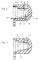
- the connecting line (27) has a radial section on and an axial section what in particular in Fig. 2 due to the enlarged view there of the closure body (24) is clearly visible.
- the connecting line (27) is thus angular formed, with an adjusting means in the apex of the angle (28) can intervene so that by suitable adjustment of the adjusting means (28) Flow cross-section of the connecting line (27) can be adjusted. It will in this case separately referred to the representation according to Fig. (5), (6) and (7), where different types of in this area arranged adjustment means (28) in enlarged view are visible.
- Fig. 5 shows a bore (29) in the apex of the angular connecting line (27) opens.
- an adjusting means (28) can be used, for example in the form of a ordinary thread screw that fits on your syringe is sharpened so as to be a fine dose Change in cross section of the connecting line (27) by turning the screw Ensure adjusting means (28).
- FIG. 6 it is also possible according to FIG. 6 to provide a cylindrical or suitable other through bore for the radial part of the connecting line (27), into which, for example, a separate bushing can be inserted, in which in turn an adjusting means (28) can be used, the different embodiments according to the F ig. 6 and 7 can also be selected or defined depending on the different choice of materials for the formation of the closure body (24).
- a threaded screw as the adjusting means (28) which has self-tapping properties, ie cuts the corresponding internal thread in the bore (29) itself when screwed into the bore.
- Fig. 3 shows the closure body (25) on the feed side or feed end of the unit Membrane body (21) and housing (13) is provided.
- both closure bodies (24), (25) can be trained identically. This is why it offers itself, as shown for example in Fig. 4, on the production side, both closure bodies (24), (25) train identically, for example according to the structure 4, in which the connecting line (27) only initially has its axial section and for the formation of the radial section the radial Hole (29) is provided separately if necessary.
- both closure bodies (24), (25) are initially trained identically to what the Manufacturing and storage costs for the device (10) would significantly reduce.
- an adapter body (35) is shown, the a structure similar to that previously described Has closure body (24), (25). There is only the Difference that in the adapter body (35) the inlet (14) or outlet (15) than in the respective axial Extension, when viewing the respective Opening sides, arranged to be viewed.
- the Adapter body (35) can have two ends, for example (22), (23) of two membrane bodies (12) and the Membrane body (12) surrounding housing tubes (13) kind of connected in series, the respective ends (22), (23) of the membrane body in the corresponding socket-like openings of the Adapter body (35) are receivable.
- the respective Membrane body (21) and the surrounding tubular Housing (13) are indicated by dash-dotted lines shown.
- the adapter body (35) has a plurality of Connecting lines (36) in the same radial distance from the axis of the adapter body (35) are arranged. These connecting lines (36) ensure the permeate (17) flows through as well of the partial retentate stream (26) from the connecting line (27) from the retentate side Closure body (24) is brought up.
- the adapter body (35) can with a corresponding majority of used adapter bodies (35) per se any number of membrane bodies (21) be connected in series, both of them Ends of the overall body thus formed in turn with the respective closure bodies (24) and (25) completed become.
- the device (10) via the inlet (14) the medium to be separated (11) (feed) supplied.
- the Medium (11) flows through the lumen of the Hollow thread membranes (12), the through the membranes (12) permeating component of the medium (11) as Permeate (17) emerges, namely into the interior of the housing (20).
- the retentate (16) leaves via the outlet (15) the device (10), wherein the in the closure body (24) trained connecting line (27) Retentate partial stream (26) is branched off and over the Holes (130) also in the interior of the housing (20) entry.
- Adjustment means (28) To regulate the flow and to relax the retentate (16), if this is compressed air, for example Ambient pressure, is by means of the previously described Adjustment means (28) an adjustment possible.
- a seal the helical sealing element (30) against the environment is with a sealant (34) guaranteed in the form of an O-ring. That as a dish soap acting retentate (16) of the partial stream (26) flows together with the permeate (17) in countercurrent to in Membrane body (21) flowing medium (11) and occurs the side of the closure body (25) as a mixture Permeate (17) and partial retentate stream (26) through the holes there (131), which thus also simultaneously Outlet (150) of the permeate (17) are.
- the device (10) can also be used for embodiments Drying or dehumidification of compressed air is used become. This is done for a certain operating pressure - as described above - a certain one Volume flow of the permeate (17) with the throttle screw set to a predeterminable dehumidification performance to reach.
- This permeate flow in the set Size flows regardless of whether a retentate stream is required, so that in the partial load and in the zero load case, i.e. when feeding a feed stream, the lower than that of the nominal state, unnecessary Retentate losses on a considerable scale occur.
- the one described below Device ensures on simple way a strong reduction of Retentate loss in the event of zero load and can additionally a reduction in the permeate flow in one compared the retentate current reduced to the nominal state (Partial load) enable.
- FIGS. 11 and 12 Cross-sectional images explained.
- the explained below Device is based on a modification of the Retentate-side closure body (see also the Closure body (24) from Fig. 1), in the following simply called retentate cap, in which the further device component described below is integrated.
- 11 contains the schematic shown modification of the retentate cap in Longitudinal section.
- the new retentate cap divided into two and consists of a lower part (51) and an upper part (52) which e.g. through the shown screws (53) are connected.
- the Membrane module (54) is described in the Lower cap part (51) fixed, e.g. by gluing, Friction welding or another connection technology.
- the retentate stream flows through hollow membrane threads (56) - here are only two hollow threads as an example (56) shown - and passes through openings (57) past a flow sensor (58) through a Outlet bore (59) out of the retentate head.
- the Permeate flow consists of two parts, namely one Main purge gas flow (60) and a basic purge gas flow (61).
- the basic purge gas flow (61) flows continuously, if a retentate stream is present, the pressure of which is greater than that of the environment.
- the basic purge gas flow is via a hole (62) directly from the retentate taken. Its volume flow can be fixed or adjustable throttle (63) can be determined and is about Channels supplied to the jacket space of the membrane module (54).
- the main purge gas stream (60) can be via another Flow channel (64) from a free volume (65) of the Retentate head are removed. It only flows when the flow sensor (58) the flow channel (64) releases.
- the one explained above Device component can be completely in the in Fig. 11th Retentate cap shown are integrated, the Execution itself to that shown in Fig. 2 Can lean on the retentate cap.
- a constant willingness to dry the Membrane dryer even at zero load is due to that constant flow of the so-called basic purge gas flow (61) given which is only a small part of the total Permeate stream - consisting of the basic and the Main purge gas flow (60.61) - makes up.
- the Basic purge gas flow (61) prevents the ingress of moist ambient air into the open holes of the Jacket tube of the module.
- the largest proportion of the permeate has the Main purge gas flow (60).
- the main goal of use the additional device component is in an adaptation of this main purge gas flow (60) to the Retentate withdrawal quantity of the membrane dryer by one To minimize the loss of retentate.
- a Adjustment of the main purge gas flow (60) can be done with a Throttle valve (66) and a main purge gas metering device (67) respectively.
- the flow of the main purge gas stream (60) is controlled by the Release of the flow channel (64) by a Main purge gas metering (67) enables.
- This is located e.g. disc-shaped Flow sensor (58), whose axial movement over Guided tours is made possible. With vertical installation the flow channel (64) is closed by the dead weight of the flow sensor (58).
- the Flow sensor (58) is therefore purely mechanical trained and has an integrated Main purge gas metering device (67).
- This flow sensor (58) can also by an axially acting spring (68). This also enables one any installation position of the membrane dryer.
- a retentate withdrawal via the opening (59) leads to a decrease in free volume pressure (65) above the flow sensor (58).
- Different versions of the main purge gas dispenser (67) and the inclusion of the flow sensor (58) in The lower part (51) of the retentate head enables one Adaptation of the main purge gas flow (60) to the amount of removed via the outlet opening (59) Retentate. This is also in from zero and Operating conditions deviating from full load, the so-called Partial load cases, a reduction in retentate losses by reducing the total permeate flow possible.
- Fig. 11 is represented by a known principle of Needle valve corresponding design of the Main permeate metering (67) can be reached.
- the Recording the flow sensor (58) in the lower part (51) the retentate head can widen axially Through openings (69) may be provided. These can - in addition to the mode of operation of the main purge gas metering device (67) -, an adaptation of the main purge gas flow (60) the amount of through the outlet opening (59) allow withdrawn stream of withdrawn.
Landscapes
- Chemical & Material Sciences (AREA)
- Chemical Kinetics & Catalysis (AREA)
- Engineering & Computer Science (AREA)
- Analytical Chemistry (AREA)
- General Chemical & Material Sciences (AREA)
- Oil, Petroleum & Natural Gas (AREA)
- Separation Using Semi-Permeable Membranes (AREA)
Claims (24)
- Dispositif pour la filtration et la séparation de milieux liquides ou gazeux (11) et / ou pour le séchage de milieux gazeux (1) en faisant usage de membranes (12), dispositif comportant une enveloppe (13) avec une entrée pour le milieu à séparer (11) et avec une sortie pour le rétentat (16) ainsi qu'avec une sortie pour le perméat, un corps de membrane (21) étant aménagé dans l'espace intérieur de l'enveloppe (20) dont les deux extrémités peuvent être délimitées à l'aide des corps de fermeture respectifs (24, 25), et un flux partiel du rétentat (16) susceptible d'être produit par le dispositif pouvant être amené sur le côté du perméat vers la membrane (12) en vue de la création d'une dépression, caractérisé en ce qu'au moins l'un des corps de fermeture (24, 25), dans lequel est aménagée la sortie pour le rétentat (18), est garni, du côté des corps de fermeture, de deux conduites de connexion (62, 64) qui reçoivent le flux partiel (26) du rétentat (16) qui s'écoule hors du corps de la membrane (21) à partir de la région de la sortie du rétentat vers l'intérieur de l'enveloppe (20) dans lequel le perméat (17) entre, un capteur d'écoulement (58) étant aménagé dans l'une des conduites de connexion (64).
- Dispositif suivant la revendication 1, caractérisé en ce que le corps de membrane (21) est formé par un grand nombre de membranes à fibres creuses (12).
- Dispositif suivant la revendication 1, caractérisé en ce que le corps de membrane (21) est formé par une membrane enroulée (12) (diaphragme enroulé).
- Dispositif suivant une ou plusieurs des revendications 1 à 3, caractérisé en ce que dans la conduite de connexion (27) est incorporé un moyen de réglage (28) agissant à la manière d'une soupape.
- Dispositif suivant la revendication 4, caractérisé en ce que le moyen de réglage (28) est constitué d'une vis filetée qui s'engage dans un logement pour filetage façonné de manière à correspondre dans un alésage (29) dans le corps de fermeture (24, 25).
- Dispositif suivant la revendication 4, caractérisé en ce que le moyen de réglage (28) est constitué d'une vis filetée autotaraudeuse qui, lors de la pose dans un alésage (29), se crée dans celui-ci un logement pour filetage par autotaraudage.
- Dispositif suivant la revendication 4, caractérisé en ce que le moyen de réglage (28) est exécuté sous la forme d'une soupape d'étranglement fixe.
- Dispositif suivant l'une quelconque des revendications 5 à 7, caractérisé en ce qu'un élément d'étanchéité élastique (34) est prévu dans l'alésage (29) en vue de l'étanchéification d'au moins la tête (31) de la vis filetée (28) par rapport à son entourage.
- Dispositif suivant une ou plusieurs des revendications 1 à 8, caractérisé en ce que le corps de fermeture (24, 25) est façonné à la manière d'une douille, tout en réservant, dans l'état de montage du corps de membrane (21) dans le corps de fermeture (24, 25), une chambre à rétentat (32) ou une chambre d'amenée (33) pour le milieu (11).
- Dispositif suivant une ou plusieurs des revendications 1 à 9, caractérisé en ce que le corps de membrane (21) est étanchéifié à l'aide d'un moyen d'étanchéité élastique (34) au moins par rapport au corps de fermeture (24) aménagé à son extrémité (22) située du côté du rétentat.
- Dispositif suivant la revendication 10, caractérisé en ce que le moyen d'étanchéité élastique (34) consiste en un joint torique.
- Dispositif suivant une ou plusieurs des revendications 1 à 11, caractérisé en ce que deux extrémités (22, 23) de corps de membrane (12) peuvent être reçues et reliées l'une à l'autre à la manière d'un montage en série au moyen d'un corps d'adaptation (35).
- Dispositif suivant la revendication 12, caractérisé en ce que le corps d'adaptation (35) possède au moins une conduite de connexion (36) qui sert à conduire le flux partiel (26) du rétentat (36) et qui traverse complètement le corps d'adaptation (35) de l'une de ses extrémités, dans laquelle est montée l'un des corps de membrane (21) respectifs, vers l'autre de ses extrémités, dans laquelle est montée l'autre corps de membrane (21).
- Dispositif suivant une ou plusieurs des revendications 1 à 13, caractérisé en ce que le corps de fermeture (24, 25) est constitué d'une matière plastique.
- Dispositif suivant une ou plusieurs des revendications 1 à 14, caractérisé en ce que le corps d'adaptation (35) est constitué d'une matière plastique.
- Dispositif suivant une ou plusieurs des revendications 1 à 15, caractérisé en ce que l'enveloppe (13) est constituée d'une matière plastique.
- Dispositif suivant une ou plusieurs des revendications 14 à 16, caractérisé en ce que la matière plastique consiste en du polypropylène.
- Dispositif suivant une ou plusieurs des revendications 14 à 17, caractérisé en ce que la matière plastique est renforcée au moyen de fibres.
- Dispositif suivant une ou plusieurs des revendications 14 à 18, caractérisé en ce que la matière plastique consiste en une matière plastique susceptible d'être injectée.
- Dispositif suivant l'une quelconque des revendications 1 à 14, caractérisé en ce qu'en vue de la détermination d'un flux volumique d'un courant de gaz de lavage de base (31) on utilise un clapet (63).
- Dispositif suivant l'une quelconque des revendications 1 à 20, caractérisé en ce que pour un courant de gaz de lavage principal (60) il est prévu un canal d'écoulement (64) dans l'étendue duquel est aménagé le capteur d'écoulement (58).
- Dispositif suivant l'une quelconque des revendications 1 à 21, caractérisé en ce qu'en vue du dosage du courant de gaz de lavage principal (60) sont prévus une soupape de modération (66) et un doseur du courant de gaz de lavage principal (67).
- Dispositif suivant l'une quelconque des revendications 1 à 22, caractérisé en ce que le capteur d'écoulement (58) se trouve sous la charge d'un ressort (68) agissant axialement.
- Dispositif suivant l'une quelconque des revendications 1 à 23, caractérisé en ce que le logement du capteur d'écoulement (58) dans le capuchon pour le rétentat est pourvu d'ouvertures (69) s'élargissant axialement.
Applications Claiming Priority (3)
| Application Number | Priority Date | Filing Date | Title |
|---|---|---|---|
| DE19716752 | 1997-04-11 | ||
| DE19716752A DE19716752C1 (de) | 1997-04-11 | 1997-04-11 | Vorrichtung zum Filtern und Trennen von flüssigen und gasförmigen Medien und/oder zum Trocknen gasförmiger Medien |
| PCT/DE1998/000913 WO1998046333A1 (fr) | 1997-04-11 | 1998-03-31 | Dispositif pour le filtrage et la separation de milieux liquides et gazeux et/ou pour le sechage de milieux gazeux |
Publications (2)
| Publication Number | Publication Date |
|---|---|
| EP0973600A1 EP0973600A1 (fr) | 2000-01-26 |
| EP0973600B1 true EP0973600B1 (fr) | 2003-11-19 |
Family
ID=7827247
Family Applications (1)
| Application Number | Title | Priority Date | Filing Date |
|---|---|---|---|
| EP98920450A Expired - Lifetime EP0973600B1 (fr) | 1997-04-11 | 1998-03-31 | Dispositif pour le filtrage et la separation de milieux liquides et gazeux et/ou pour le sechage de milieux gazeux |
Country Status (4)
| Country | Link |
|---|---|
| EP (1) | EP0973600B1 (fr) |
| AU (1) | AU7330598A (fr) |
| DE (1) | DE19716752C1 (fr) |
| WO (1) | WO1998046333A1 (fr) |
Families Citing this family (4)
| Publication number | Priority date | Publication date | Assignee | Title |
|---|---|---|---|---|
| DE10259661A1 (de) * | 2002-10-16 | 2004-04-29 | Beko Technologies Gmbh | Hohlfaser-Modul |
| DE102008036098B4 (de) * | 2008-08-04 | 2016-04-28 | Mn-Beteiligungs-Gmbh | Filtermodul mit spiralförmig gewickelten Flachfiltern, Verfahren zu dessen Herstellung und daraus aufgebautes Filtrationssystem |
| CN103691323A (zh) * | 2014-01-08 | 2014-04-02 | 天津工业大学 | 一种外压中空纤维膜组件 |
| CN114653212B (zh) * | 2021-12-15 | 2023-10-03 | 临沂泽宇环保科技有限公司 | 一种海洋污水膜分离过滤装置 |
Family Cites Families (7)
| Publication number | Priority date | Publication date | Assignee | Title |
|---|---|---|---|---|
| US3735558A (en) * | 1971-06-29 | 1973-05-29 | Perma Pure Process Inc | Process for separating fluids and apparatus |
| JPH0232929U (fr) * | 1988-08-19 | 1990-03-01 | ||
| DE9300929U1 (de) * | 1993-01-23 | 1993-04-08 | Gkss-Forschungszentrum Geesthacht Gmbh, 21502 Geesthacht | Vorrichtung zum Filtern und Trennen von flüssigen und gasförmigen Medien und/oder zum Be- und Entgasen von Flüssigkeiten |
| US5411662A (en) * | 1994-02-25 | 1995-05-02 | Praxair Technology, Inc. | Fluid separation assembly having an purge control valve |
| US5525143A (en) * | 1994-10-17 | 1996-06-11 | Air Products And Chemicals, Inc. | Hollow fiber membrane dryer with internal sweep |
| US5605564A (en) * | 1996-02-14 | 1997-02-25 | Howell Laboratories, Inc. | Membrane gas dehydrator |
| FR2751894B1 (fr) * | 1996-07-31 | 1998-09-18 | Jacob Jacques | Procede de fabrication de gaz comprime sec, notamment d'air comprime sec, dispositif pour sa mise en oeuvre et son application a usage medical |
-
1997
- 1997-04-11 DE DE19716752A patent/DE19716752C1/de not_active Expired - Fee Related
-
1998
- 1998-03-31 EP EP98920450A patent/EP0973600B1/fr not_active Expired - Lifetime
- 1998-03-31 WO PCT/DE1998/000913 patent/WO1998046333A1/fr not_active Ceased
- 1998-03-31 AU AU73305/98A patent/AU7330598A/en not_active Abandoned
Also Published As
| Publication number | Publication date |
|---|---|
| AU7330598A (en) | 1998-11-11 |
| DE19716752C1 (de) | 1998-06-18 |
| WO1998046333A1 (fr) | 1998-10-22 |
| EP0973600A1 (fr) | 2000-01-26 |
Similar Documents
| Publication | Publication Date | Title |
|---|---|---|
| DE69501909T2 (de) | Vorrichtung zur Fluidabtrennung mit integralem Entlüftungssteuerungsventil | |
| DE60004037T2 (de) | Hohlfasernmembranvorrichtungen und verfahren zu deren montage | |
| EP0254100B1 (fr) | Dispositif pour éliminer les bulles de gaz des fluides | |
| DE3851167T2 (de) | Spiralförmig gewickelte, konische Filterpatrone und Verfahren zu ihrer Herstellung. | |
| EP0371189B1 (fr) | Module à fibres creuses, procédé de fabrication dudit module et appareil pour la mise en oeuvre dudit procédé de fabrication | |
| EP0291921B1 (fr) | Système d'échange de matière, spécialement pour mouiller des gaz | |
| DE2338070B2 (de) | Fraktionierungsvorrichtung | |
| DE3687520T2 (de) | Gehaeuseende mit gewinde. | |
| WO2002022244A1 (fr) | Filtre a membrane pour traitement de l'eau | |
| DE8232380U1 (de) | Kuenstliche hohlfaser-lunge mit angebautem waermetauscher | |
| DE7026643U (de) | Vorrichtung zur durchfuehrung der umgekehrten osmose. | |
| DE3143965A1 (de) | Zigarettenfilter | |
| DE8008172U1 (de) | Vorrichtung zur herstellung von kunststoffrohren mit laengslaufenden hohlkanaelen in deren wandung | |
| DE2757838A1 (de) | Vorrichtung mit hohlfasern zur fraktionierung von fluiden | |
| DE3650292T2 (de) | Hohlfasermodul für Trennungsverfahren. | |
| EP0973600B1 (fr) | Dispositif pour le filtrage et la separation de milieux liquides et gazeux et/ou pour le sechage de milieux gazeux | |
| DE4308850A1 (de) | Hohlfadenmatte | |
| DE4401014C2 (de) | Vorrichtung zum Filtern und Trennen von flüssigen und gasförmigen Medien und/oder zum Be- und Entgasen von Flüssigkeiten | |
| DE2945317C2 (de) | Vorrichtung zur Wasserentsalzung und -reinigung durch Umgekehrte Osmose und Ultrafiltration | |
| DE3519620A1 (de) | Einrichtung und verfahren zur steuerung der diffusion von fluidkomponenten | |
| DE2950426C2 (de) | Vorrichtung zum Trennen von Strömungsmitteln | |
| WO2006012920A1 (fr) | Membrane de filtrage et procede de realisation | |
| DE3611623A1 (de) | Stoff- und/oder waermeaustauscher | |
| EP0350853B1 (fr) | Procédé et appareil pour filtrer des dispersions gazeuses ou liquides | |
| DE20303013U1 (de) | Vorrichtung zum Filtern und Trennen von Strömungsmedien |
Legal Events
| Date | Code | Title | Description |
|---|---|---|---|
| PUAI | Public reference made under article 153(3) epc to a published international application that has entered the european phase |
Free format text: ORIGINAL CODE: 0009012 |
|
| AK | Designated contracting states |
Kind code of ref document: A1 Designated state(s): ES FR GB IT |
|
| 17P | Request for examination filed |
Effective date: 19991015 |
|
| 17Q | First examination report despatched |
Effective date: 20010629 |
|
| GRAH | Despatch of communication of intention to grant a patent |
Free format text: ORIGINAL CODE: EPIDOS IGRA |
|
| GRAS | Grant fee paid |
Free format text: ORIGINAL CODE: EPIDOSNIGR3 |
|
| GRAA | (expected) grant |
Free format text: ORIGINAL CODE: 0009210 |
|
| AK | Designated contracting states |
Kind code of ref document: B1 Designated state(s): ES FR GB IT |
|
| PG25 | Lapsed in a contracting state [announced via postgrant information from national office to epo] |
Ref country code: IT Free format text: LAPSE BECAUSE OF FAILURE TO SUBMIT A TRANSLATION OF THE DESCRIPTION OR TO PAY THE FEE WITHIN THE PRESCRIBED TIME-LIMIT;WARNING: LAPSES OF ITALIAN PATENTS WITH EFFECTIVE DATE BEFORE 2007 MAY HAVE OCCURRED AT ANY TIME BEFORE 2007. THE CORRECT EFFECTIVE DATE MAY BE DIFFERENT FROM THE ONE RECORDED. Effective date: 20031119 Ref country code: GB Free format text: LAPSE BECAUSE OF FAILURE TO SUBMIT A TRANSLATION OF THE DESCRIPTION OR TO PAY THE FEE WITHIN THE PRESCRIBED TIME-LIMIT Effective date: 20031119 Ref country code: FR Free format text: LAPSE BECAUSE OF FAILURE TO SUBMIT A TRANSLATION OF THE DESCRIPTION OR TO PAY THE FEE WITHIN THE PRESCRIBED TIME-LIMIT Effective date: 20031119 |
|
| REG | Reference to a national code |
Ref country code: GB Ref legal event code: FG4D Free format text: NOT ENGLISH |
|
| PG25 | Lapsed in a contracting state [announced via postgrant information from national office to epo] |
Ref country code: ES Free format text: LAPSE BECAUSE OF FAILURE TO SUBMIT A TRANSLATION OF THE DESCRIPTION OR TO PAY THE FEE WITHIN THE PRESCRIBED TIME-LIMIT Effective date: 20040302 |
|
| GBV | Gb: ep patent (uk) treated as always having been void in accordance with gb section 77(7)/1977 [no translation filed] |
Effective date: 20031119 |
|
| PLBE | No opposition filed within time limit |
Free format text: ORIGINAL CODE: 0009261 |
|
| STAA | Information on the status of an ep patent application or granted ep patent |
Free format text: STATUS: NO OPPOSITION FILED WITHIN TIME LIMIT |
|
| 26N | No opposition filed |
Effective date: 20040820 |
|
| EN | Fr: translation not filed |