EP0973628B1 - Systeme de regulation de soudure par resistance, au moyen d'une compensation d'impedance de la ligne - Google Patents
Systeme de regulation de soudure par resistance, au moyen d'une compensation d'impedance de la ligne Download PDFInfo
- Publication number
- EP0973628B1 EP0973628B1 EP99904242A EP99904242A EP0973628B1 EP 0973628 B1 EP0973628 B1 EP 0973628B1 EP 99904242 A EP99904242 A EP 99904242A EP 99904242 A EP99904242 A EP 99904242A EP 0973628 B1 EP0973628 B1 EP 0973628B1
- Authority
- EP
- European Patent Office
- Prior art keywords
- weld
- current
- voltage
- line
- cycle
- Prior art date
- Legal status (The legal status is an assumption and is not a legal conclusion. Google has not performed a legal analysis and makes no representation as to the accuracy of the status listed.)
- Expired - Lifetime
Links
- 238000010304 firing Methods 0.000 claims description 74
- 238000003466 welding Methods 0.000 claims description 23
- 238000000034 method Methods 0.000 claims description 16
- 230000006870 function Effects 0.000 description 27
- 238000010586 diagram Methods 0.000 description 8
- 230000008569 process Effects 0.000 description 7
- 230000004044 response Effects 0.000 description 5
- 230000001052 transient effect Effects 0.000 description 5
- 238000013461 design Methods 0.000 description 4
- 238000009826 distribution Methods 0.000 description 4
- 230000000694 effects Effects 0.000 description 4
- 239000007787 solid Substances 0.000 description 4
- 238000013459 approach Methods 0.000 description 3
- 230000001939 inductive effect Effects 0.000 description 3
- 230000008859 change Effects 0.000 description 2
- 238000004891 communication Methods 0.000 description 2
- 230000003111 delayed effect Effects 0.000 description 2
- 230000001419 dependent effect Effects 0.000 description 2
- 230000006872 improvement Effects 0.000 description 2
- 230000000977 initiatory effect Effects 0.000 description 2
- 238000004519 manufacturing process Methods 0.000 description 2
- 229910052751 metal Inorganic materials 0.000 description 2
- 239000002184 metal Substances 0.000 description 2
- 238000012360 testing method Methods 0.000 description 2
- 101100136062 Mycobacterium tuberculosis (strain ATCC 25618 / H37Rv) PE10 gene Proteins 0.000 description 1
- XUIMIQQOPSSXEZ-UHFFFAOYSA-N Silicon Chemical compound [Si] XUIMIQQOPSSXEZ-UHFFFAOYSA-N 0.000 description 1
- 229910000831 Steel Inorganic materials 0.000 description 1
- 229910052782 aluminium Inorganic materials 0.000 description 1
- XAGFODPZIPBFFR-UHFFFAOYSA-N aluminium Chemical compound [Al] XAGFODPZIPBFFR-UHFFFAOYSA-N 0.000 description 1
- 230000006399 behavior Effects 0.000 description 1
- 230000009286 beneficial effect Effects 0.000 description 1
- 210000004556 brain Anatomy 0.000 description 1
- 238000004364 calculation method Methods 0.000 description 1
- 238000011217 control strategy Methods 0.000 description 1
- 238000012937 correction Methods 0.000 description 1
- 239000013078 crystal Substances 0.000 description 1
- 230000001934 delay Effects 0.000 description 1
- 238000013101 initial test Methods 0.000 description 1
- 238000005304 joining Methods 0.000 description 1
- 238000005259 measurement Methods 0.000 description 1
- 150000002739 metals Chemical class 0.000 description 1
- 238000012986 modification Methods 0.000 description 1
- 230000004048 modification Effects 0.000 description 1
- 238000007781 pre-processing Methods 0.000 description 1
- 239000004065 semiconductor Substances 0.000 description 1
- 238000007493 shaping process Methods 0.000 description 1
- 229910052710 silicon Inorganic materials 0.000 description 1
- 239000010703 silicon Substances 0.000 description 1
- 239000010959 steel Substances 0.000 description 1
- 239000000126 substance Substances 0.000 description 1
- 230000001360 synchronised effect Effects 0.000 description 1
- 238000010200 validation analysis Methods 0.000 description 1
Images




Classifications
-
- B—PERFORMING OPERATIONS; TRANSPORTING
- B23—MACHINE TOOLS; METAL-WORKING NOT OTHERWISE PROVIDED FOR
- B23K—SOLDERING OR UNSOLDERING; WELDING; CLADDING OR PLATING BY SOLDERING OR WELDING; CUTTING BY APPLYING HEAT LOCALLY, e.g. FLAME CUTTING; WORKING BY LASER BEAM
- B23K11/00—Resistance welding; Severing by resistance heating
- B23K11/24—Electric supply or control circuits therefor
- B23K11/25—Monitoring devices
- B23K11/252—Monitoring devices using digital means
Definitions
- Applicants' invention relates generally to the field of weld controllers and more particularly to a weld controller system which automatically compensates for the effects of line impedance, which cause variations in the input line voltage, to maintain a constant output RMS current to a workpiece being welded by the weld controller.
- weld controllers have become more sophisticated and use a variety of control techniques to ensure the quality of welds throughout the life of the contact tips as they wear out.
- most weld controllers consist of several basic components. These include a weld control module, a power module, a weld transformer and the contact tips.
- the power module usually consists of power semiconductors such as silicon controlled rectifiers (SCRs) that switch incoming power to the weld transformer according to a preset weld program as generated by the control module.
- SCRs silicon controlled rectifiers
- the weld transformer will transform the incoming power to a high current pulse that is coupled to the contact tips to create a weld to a workpiece that is between the contact tips.
- a weld program will use phase angle control to switch the power modules.
- the proper phase angle to fire the SCRs will be a function of the condition of the power source delivering power to the weld control and subsequently through the weld control to the weld transformer.
- the actual line voltage is a function not only of the source voltage but also of line impedance.
- the line voltage can differ from the nominal designed voltage since the voltage source is a real voltage source generated by a power company and subject to a power distribution system and hence may not be at the nominal design voltage of the weld control.
- the presence of line impedance causes a voltage drop proportional to the current flowing into the weld. Comparing the actual weld current to a targeted load current, it is proportional to the ratio of the actual line voltage to the nominal line voltage and it is reduced by a factor that is a function of the ratio of the nominal load current to the total available nominal short circuit current of the weld.
- the prior art assumes that the voltage source is stiff with no line impedance.
- the premise is that the weld controller is capable of measuring the line voltage of the weld controller from a present weld pulse and can correct the next weld pulse based on this measurement. In the steady state, this provides the desired result. However, there is a transient response associated with this approach which limits its effectiveness.
- the actual weld load current will be the nominal load current. However, the first two cycles of weld current are significantly lower than the nominal desired current for power distribution systems that are very stiff since the initial load current does not deviate significantly from the nominal desired current.
- the prior art while providing excellent steady state response, has a transient characteristic which is undesirable in welding applications, particularly where a small number of cycles are used to create the weld, such as in aluminum welding.
- a weld pulse comprising only 3-6 cycles of relatively high current is very common in modern applications, so an improvement in the transient response of the weld control would be most beneficial.
- US Patent Number 5,869,800 describes a phase controlled weld controller system which estimates a phase error between an internal phase reference generator and the voltage source. The system also estimates the phase distortion generated by the weld control when operating with an inductive impedance load when significant line impedance is present.
- the principal object of the present invention is to provide a phase controlled weld controller system that uses an internal model of weld line and load impedance and of open circuit weld input voltage to develop a nominal firing angle sequence to maintain a desired weld current or conduction angle sequence.
- Another object of the present invention is to provide a phase controlled weld controller system that estimates an expected weld line and load impedance and open circuit line voltage to develop the internal model.
- a further objective of the invention is to provide a method and apparatus to accurately measure the weld line and load impedance and line voltage during a weld sequence.
- Yet another objective of the invention is to provide a method and apparatus for utilizing the measured and estimated weld line and load impedance to determine an expected line voltage if the desired weld sequence is maintained.
- a digital weld control system for a resistance welder of the type connecting and disconnecting through a welding contactor, a welding transformer load from an alternating current weld power source to control timing periods of a welding sequence and a level of heat intensity in the weld to ensure quality welds, the digital weld control system comprising:
- one control variable relates to the timing of the firing pulses to the SCRs relative to the input line voltage.
- the weld controller is treated as a discrete time system, with the inputs, outputs and state variables represented as mathematical sequences, rather than as continuously time varying quantities, with the smallest unit in a sequence representing a half-cycle of the AC power source in time.
- the inputs, outputs and state variables represented as mathematical sequences, rather than as continuously time varying quantities, with the smallest unit in a sequence representing a half-cycle of the AC power source in time.
- the present invention creates an internal lumped parameter model of the weld power source comprising an ideal voltage source and lumped line impedance and internal lumped parameter model of the load impedance in the form of a relation between expected load current and conduction angle.
- the weld controller computes a nominal fixing angle sequence based on estimated models of line impedance, open circuit voltage, and estimated relation between the load current and conduction angle and the mathematical relation between firing angle, conduction angle and load circuit power factor that will achieve the desired weld sequence if the models are accurate. This process of using such a model developed a-priori to compute nominal control signals is commonly known as a feed forward control.
- the weld controller subsequently uses measured values received in real time while the weld sequence is being executed to modify the nominal firing angle to better achieve the desired objective.
- This process of adjusting a control parameter in real time in response to an error between the target and observed parametric value is referred to as closed loop feedback control.
- This approach allows the weld controller to quickly achieve the desired weld sequence with the actual load, while permitting low feedback gains, resulting in a system that is quick and accurate in response without being overly sensitive.
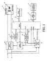
- FIG. 1 shows an overview block diagram of a basic weld controller 10.
- a source of weld power is connected to the weld controller via the input lines L1 and L2.
- the weld controller is programmed via a serial communication link 12 tied to a weld programmer 14, external to the weld controller 10.
- execution of the weld program is initiated via external equipment 16, which is wired to weld sequence I/O 18 which subsequently breaks the weld program down into one or more weld command pulses 19.
- the output of the weld controller 10 is wired to a weld transformer 20 and gun 22, which passes current through a workpiece comprising two or more pieces of metal that are to be joined.
- the weld controller 10 also includes a weld regulator 24, a firing control module 26, and a phase reference clock 28.
- Digital voltage meter 30 is used to measure various parameters of the input line voltage L1-L2, such as volt-time area, and polarity.
- a current sensor 32 generates a current signal H1, H2 proportional to the current flowing in the primary of the weld transformer 20.
- a digital current meter 34 is used to measure various parameters of the primary load current, such as current-time area, polarity, and conduction time.
- the weld regulator 24 consists of a microprocessor, associated program and data memory, and a time base reference source such as a crystal controlled clock.
- the weld regulator 24 is the functional brain of the weld controller 10 and interacts with all of the other functions to generate the appropriate timing signals to fire a solid state weld contactor 36 through the firing control module 26, which is synchronized with the phase reference clock 28 under software control.
- the solid state weld contactor 36 switches line voltage upon command in the form of firing pulses from the firing controller.
- This contactor generally comprises a pair of back to back thyristors with associated snubbing, level shifting and pulse shaping circuits required to accept the firing pulses.
- the weld sequence I/O 18 comprises a hardware interface to external equipment 16 which may take the form of hard-wired digital inputs and outputs, or one of several serial communication interfaces per various commercial standards, and software that upon initiation of a weld program generates one or more weld command pulses 19 to the weld regulator.
- the phase reference clock 28 is a free-running clock which operates independent of software delays.
- the phase reference clock provides an internal time base for the solid state contactor firing pulses based on an estimate of the frequency and phase of the incoming line voltage L1 and L2.
- the period of the phase reference clock can be set and modified under software control.
- the phase reference clock is implemented in hardware external to the weld regulator 24, utilizing a commonly available programmable counter. In operation, the counter is programmed to generate a square wave which becomes an interrupt sequence used by the weld regulator 24. The period of the counter is programmed by the weld regulator 24, which sets the period of the clock to track the input line voltage. Details of the phase reference clock 28, the digital voltmeter 30, and the digital current meter 34 are disclosed in US Patent No. 5,869,800 entitled "Phase Distortion Compensated Time Base for a Weld Controller".
- the weld controller 10 supports two weld control types: A Percent Current (%I) weld which adjusts thyristor firing angles to regulate a voltage and line impedance compensated conduction angle representing a percentage of maximum weld current into an assumed load impedance, and a Constant Current weld which adjusts the thyristor firing angles to achieve a target current directly.
- %I Weld commands indicate a percentage of the maximum controllable current as determined from an estimated relation between the solid state contactor conduction angle and expected weld current as stored in a I- ⁇ table. The term maximum controllable current will be defined subsequently.
- the first form of the %I command is intended to deliver a constant weld pulse of XX cycles at YY percent of maximum controllable current.
- the second form is intended to ramp the weld current from Y1 to Y2 percent of maximum controllable current linearly over XX cycles of weld.
- Constant Current weld commands in the weld controller 10 include a first form that attempts to deliver a weld current of YY Amperes RMS to the primary of the weld transformer over a period of XX cycles.
- the second form allows a user to program a desired secondary current, which the weld controller 10 subsequently converts to primary amperes from a knowledge of the weld transformer turns ratio.
- the third form of the weld command attempts to create a linear ramp of weld current from Y1 Amperes to Y2 Amperes over a period of XX cycles
- the fourth command allows the user to specify the weld current targets for the linear ramp in secondary kilo-Amperes, which are subsequently converted by the weld controller 10 to primary amperes.
- FIG. 2 is a simplified lumped parameter circuit model 40 for the resistance weld controller 10, and associated power distribution system and weld load which will be used to derive mathematics of the weld controller 10.
- the lumped parameter model 40 comprises a weld power source 42, the weld controller 10 and a weld load impedance 44.
- the weld power source 42 is modeled as two circuit elements, a voltage source 46, which is assumed to be an ideal voltage source having no series impedance and a serially connected lumped line impedance, Z line , which is assumed to be ideal and linear and which generates a voltage drop between the ideal voltage source and the weld control proportional to the weld load current.
- the weld controller 10 is capable of observing the load current I load and the voltage applied at its input terminals, V wc . Utilizing thyristor based phase control, the weld controller generates a weld voltage V load at its output terminals, with a corresponding weld current I load .
- the weld load impedance 44 comprises the weld transformer 20, workpiece, tooling 22, fixtures and other sources of impedance. To simplify the mathematics, the impedance of all these elements are lumped into a single impedance quantity reflected at the output terminals of the weld control as Z load . When the weld control applies the voltage V load upon the load impedance, the resulting current is I load .
- Thyristor voltage when conducting into an inductive load, as in the case in a normal resistance weld application, is well known.
- the sinusoidal voltage source is scaled in degrees instead of time. With the sinusoid defined in degrees, the thyristor is fired at an angle ⁇ with respect to the phase reference clock which nominally tracks the zero crossings of the sinusoidal voltage source, at which time the thyristor begins to conduct current.
- ⁇ arccos ( p f )
- Equations (3) and (4) above relate the firing angle, conduction angle and load power factor.
- a table-lookup scheme with linear interpolation in both the firing angle and conduction angle directions is employed to determine the circuit power factor and firing angle.
- This becomes a Dynamic I- ⁇ curve (DIG) model, maintained within the weld controller 10 and provides an expected relationship between the conduction angle and expected resulting weld current at nominal line voltage, V nom .
- DIG Dynamic I- ⁇ curve
- the maximum controllable weld current, I max is defined as that current given by the Dynamic I- ⁇ curve at 170 degrees conduction angle, allowing for a 10 degree correction in conduction angle target to compensate for the effects of line voltage variation and line impedance at the highest %I values.
- the target current is the percentage of I max indicated.
- the %I corresponding to a target current in a constant current weld is determined by dividing the target current by I max .
- the line voltage is not the nominal line voltage on which the DIG model is based or the DIG model is not an accurate representation of the load impedance.
- V load ( n ) V w c ( n ) ⁇ % I max ( n )
- the feedforward path of the weld controller will generate a firing angle that attempts to apply this percentage of the nominal weld voltage to the load.
- the present invention estimates a line that will result when the SCRs are fired.
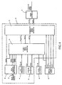
- Figure 4 shows a block diagram of the weld regulator 24 of Fig. 1. It is the central element of the weld controller 10 and interacts with all of the other functions to determine and generate the appropriate timing signals to fire the thyristors through the firing controller module 26. Its function is to develop a nominal firing angle sequence that would develop a correct weld sequence, assuming that the load impedance, line impedance and line voltage can be estimated exactly, then make minor adjustments to the nominal sequence based on the actual observed behavior of the system while in operation.
- the two main blocks of the weld regulator 24 are a compensated firing angle generator 50 which modifies the nominal sequence, and a nominal firing angle generator 52.
- a weld command preprocessor function 56 derives information from the pth weld pulse command as programmed by an operator, including a starting target value, Startl(p), of primary current for this pth pulse, an ending target value, EndI(p), of primary current for this pth pulse, the number of cycles Cycles(p) of weld in the pth pulse, and the weld type (%I or CCWELD), labeled Type(p).
- preprocessing involves converting any secondary current values entered into primary currents (using the specified transformer turns ratio) and extracting the information above.
- the programmed percentages are converted into target primary currents by multiplying the user programmed percentage by I max , the current from the DIG that would be supplied by the weld control into the nominal estimated load at nominal designed voltage at a conduction angle of 170 degrees as described above.
- Startl(p), Endl(p), Cycles(p) and Type(p) are all inputs to the nominal firing angle generator 52, and Type(p) is also an input to the compensated firing angle generator.
- a line impedance estimator function 58 provides an estimate of the line impedance z • line to the nominal firing angle generator 52.
- a dynamic I- ⁇ estimator function 54 maintains an a-priori estimate of the load power factor, PF(p), and a table of estimated I- ⁇ values, DIG(p), both derived from previous welds using a method to be described subsequently.
- the digital voltmeter function 30 furnishes an estimate V - (n) of the RMS line voltage for the negative half cycle of each cycle of line voltage to the nominal firing angle generator 52.
- the digital current meter function 34 furnishes an estimated sequence I - (n) of the RMS current for each negative half cycle, to both the nominal firing angle generator 52 and compensated firing angle generator 50, as well as furnishing the sequence of estimated positive half-cycle current, I + (n-1), the negative conduction angle sequence, ⁇ - (n) and positive conduction angle sequence ⁇ + (n-1) to the compensated firing angle generator 50.
- the nominal firing angle generator 52 provides a sequence of nominal firing angles, ⁇ nom (n+1), a compensated target conduction angle sequence, ⁇ t (n+1) and a target current sequence, I t (n+1) to the compensated firing angle generator 50.
- the compensated firing angle generator 50 provides a sequence of positive half-cycle firing angles, ⁇ + (n+1) and a sequence of negative half-cycle firing angle values ⁇ - (n+1) to the firing controller 26, which outputs of the sequence of electrical impulses that trigger the thyristor, causing weld current to flow.
- FIG. 5 provides details of the nominal firing angle generator 52.
- a weld trajectory generator 60 generates a sequence, I t (n+1), of nominal target currents, with the index "n+1" denoting that the output of the trajectory generator is the value of the nominal current for the next cycle of weld.
- a line impedance compensator function 62 adjusts the nominal current trajectory computed by the weld trajectory generator 60 for the effects of line impedance and voltage variations according to the mathematics above.
- the estimate of line impedance Z line • (p) for the pth weld pulse, generated by the line impedance estimator function 58 is one input to the line impedance compensator 62, as well as the cycle number.
- the line voltage estimate from the previous weld cycle, V - (n-1) is furnished to the line impedance compensator 62 from the digital voltmeter 30. Also furnished is the nominal line voltage, V nom , a design parameter dependent on the application of the control.
- the sequence of line impedance compensated target currents, I tc (n+1), is subsequently fed to a target conduction angle generator 64, which utilizes the Dynamic I- ⁇ curve sequence DIG(p) generated by the dynamic I- ⁇ estimator function 54 to compute a sequence of target conduction angles, ⁇ t (n+1) for the next pulse.
- This target conduction angle sequence along with the estimate of the system power factor, PF(p), also furnished by the dynamic I- ⁇ estimator 54, is fed to a nominal firing angle generator 66, which utilizes a digitized version of a surface relating firing angle, conduction angle and power factor and a combination of a table-lookup scheme and linear interpolation in two dimensions to compute a nominal firing angle sequence ⁇ nom (n+1).
- the output sequence ⁇ nom (n+1) becomes the feedforward firing angle sequence in the weld controller 10 strategy and is one input to the firing angle compensator 50, the internal operational details of which take different forms dependent upon the weld type (%I or Constant Current
- firing angle compensator 50 Other inputs to the firing angle compensator 50 are the measured positive and negative conduction angle sequences ⁇ + (n-1) and ⁇ - (n), the measured positive and negative current sequences, I + (n-1) and I - (n), all of which are furnished by the digital current meter 34, and the weld type (Constant Current or %I).
- the outputs of the firing angle compensator are two sequences of firing angles, ⁇ - (n+1) and ⁇ + (n+1).
- FIG. 6 shows an expanded block diagram of the firing angle compensator 50.
- the weld type, nominal firing angle, target conduction angle sequence, target current sequence and the measured currents and conduction angles from the previous positive and negative half cycles are inputs to a feedback compensator function 70.
- the output of the feedback compensator 70 is the sequence of compensated firing angles, ⁇ c (n+1), and represent the system's best guess of the correct firing angles to employ on the next full cycle of welding.
- This sequence of firing angles ⁇ c (n+1) is subsequently passed through a delayed firing compensator function 72, which applies a lower limit to the first and last half cycle of a weld pulse under certain circumstances.
- the outputs of the delayed firing generator 72 are the respective target firing angles for the next cycle of weld, ⁇ df- (n+1) and ⁇ df+ (n+1).
- One final check on the computed firing angles is performed prior to converting them to timing signals and applying firing pulses to the thyristors.
- a dynamic firing angle limit function 74 is applied to the firing pulse based on the previous negative half cycle firing angle ⁇ df- (n) and the resulting observed conduction angle ⁇ - (n) to ensure that the firing angles do not cause a half-cycling condition. These values are converted to timer counts and subsequently feed a firing angle timer.
- Figure 7 expands the feedback compensator 70 of Figure 6 in the %I mode.
- This system block is implemented in system software and is conditionally executed on each cycle of weld based on the test: I ⁇ ( n ⁇ 1 ) > ( 1 ⁇ ⁇ ) I t ( n ⁇ 1 )
- the weld controller 10 tests the previous weld current to ensure that it lies within a percentage of its target value. This condition would be violated if, for instance, insufficient pressure were applied to the weld gun so that it did not close, or if there was an insulating substance between the weld electrode(s) and the workpiece such as a sticker.
- the weld controller 10 freezes the closed loop feedback control for that cycle, using the previous firing angle until either the programmed number of cycles is complete, a more serious error condition is detected or the current falls within the range prescribed by (12).
- ⁇ is set at .25, which means that the measured weld current needs to be within 75% of the expected value for the compensation algorithm to be executed.
- K g is the imbalance gain of the control loop
- K ipct is the integral gain term.
- K g and K ipct are set to 0.5 each.
- Figure 8 shows the feedback compensator function 70 in the Constant Current welding mode. Again, the compensator is executed conditionally according to Equation (12) above. In this case, the nominal firing angle is adjusted based on a direct comparison of the nominal weld current against the observed weld current. Two state variables, labeled x1(n) and x2(n) are shown in Figure 8.
- Figure 9 expands the dynamic I-g estimator 54 of the weld regulator 50.
- the firing angle ⁇ upd (p), resulting conduction angle ⁇ upd (p), measured line voltage V upd (p) and measured load current I upd (p) corresponding to the last negative half cycle of weld pulse p are used to compute a new estimate of the load impedance power factor and corresponding I- ⁇ curve.
- ⁇ upd (p) and ⁇ upd (p) are inputs to a routine shown in the block diagram as Compute Pulse Power Factor (PE1).
- PE1 Compute Pulse Power Factor
- This function utilizes the digitized relation between firing angle, conduction angle and power factor described previously in a table lookup scheme with interpolation to compute the weld load power factor from a knowledge of the firing angle and conduction angle.
- the output of this function is a scalar quantity labeled PFp(p).
- This scalar power factor forms the input to a digital filter (PE2), which computes an estimated system PF(p+1), reducing weld to weld fluctuations in estimated system power factor.
- k fr is presently set to a value of 0.25.
- the initial value of the filter in the weld controller 10 is 30%, which represents the lowest value of power factor likely to be seen in the resistance welding application.
- the DIG-for a given weld schedule is represented by a vector of 19 points corresponding to increments of 10 degrees of conduction angle between the ranges of 0 to 180 degrees inclusive.
- a digitized representation of the surface in Figure 7 is stored in the microprocessor's memory.
- the estimated power factor pf(p+1) is input to a software function that uses a combination of a table lookup and linear interpolation to compute a vector of normalized I-g values as a function of the power factor (PE3).
- the output of this function is labeled I- ⁇ norm (p+1, ⁇ ).
- the normalized I-g table is subsequently evaluated at the update conduction angle, ⁇ upd (PE4) to determine the percentage of maximum current represented by the conduction angle. This value is denoted %I abs (p+1).
- I 180m (p+1) The estimated current available at 180 degrees conduction angle, I 180m (p+1) is determined by dividing (PE5) the actual measured update current, I upd (p) by %I abs (p+1).
- I 180m (p+1) is an estimate of the maximum current attainable by the weld controller at full conduction, assuming the voltage source is stiff and at the line voltage measured; V upd (p). Since the Dynamic I- ⁇ table is defined as the operating characteristic of the weld control at nominal line voltage, I 180m (p+1) is adjusted for the line voltage by multiplying by the ratio of the nominal line voltage to the measured line voltage, V upd (p) (PE6). The output of this voltage compensator is I 180vc (p+1).
- This value is subsequently passed through a digital filter (PE7) in a manner identical to that of the pulse power factor to obtain the maximum current estimate I 180 (p+1).
- PE7 digital filter
- I- ⁇ norm (p+1) the maximum current estimate I max (p+1) (PE8)
- DIG estimate could be made in several other ways without violating the spirit of the present invention.
- One implementation that has been successfully demonstrated uses the average weld voltage and weld current for the pth weld pulse as the update value.
- the line impedance estimator 58 uses measured line voltages and currents from previous welds to develop estimates of the magnitude of line impedance. It is assumed that the line impedance varies slowly with respect to the weld pulse. For instance, while a resistance weld control may be called upon to make several welds in a minute, it is assumed that changes in line impedance are detectable over time periods considerably larger. No such assumption is made regarding changes in the Thevenin equivalent voltage of the lumped parameter block diagram of Figure 1, so that some care is required in the estimation process as described below.
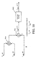
- Figure 10 shows the process of computing a new estimate of line impedance. This estimate is computed after each "normally completed" weld pulse, subject to validation of the data.
- V oc (p) is the last known open circuit voltage, i.e. the line voltage of the last half cycle for which it is known that no weld current flowed. It is assumed that V oc (p) accurately represents the value of the Thevenin equivalent voltage source V s in the lumped parameter model of Figure 3, and that value does not change appreciably during the weld pulse.
- V oc (p) the open circuit voltage, V oc (p) is first compared PE10 against the update voltage, V upd (p), which is the same line voltage associated with the last negative half cycle of weld current used to update the DIG as described above. If the update voltage, V upd (p) is greater than or equal to V oc (p), then clearly the value of the Thevenin equivalent voltage source V s in Figure 3 has changed considerably and no update of the line impedance estimate is made.
Landscapes
- Engineering & Computer Science (AREA)
- Mechanical Engineering (AREA)
- Arc Welding Control (AREA)
- Feedback Control In General (AREA)
- Generation Of Surge Voltage And Current (AREA)
- Control Of Voltage And Current In General (AREA)
Claims (6)
- Système numérique de contrôle de soudure pour un dispositif de soudure à résistance du type à connexion et à déconnexion à travers un contacteur de soudure, une charge de transformateur de soudure à partir d'une source d'alimentation électrique de soudure à courant alternatif pour contrôler des périodes de synchronisation d'une séquence de soudure et un niveau d'intensité thermique dans la soudure pour assurer des soudures de qualité, le système numérique de contrôle de soudure comprenant :a. une horloge de référence de phase ;b. un voltmètre ;c. un ampèremètre ;d. un contrôle d'amorçage ;
caractérisé en ce que le système numérique de contrôle de soudure comprend en outree. un estimateur d'impédance pour estimer la grandeur d'impédance de charge et le facteur de puissance sur la base des données des soudures précédentes ;f. un estimateur de source d'alimentation électrique pour estimer une puissance de source sur la base d'un modèle de paramètre en bloc de la source de puissance de soudure ; etg. un moyen de contrôle qui réagit au modèle de paramètre en bloc, à l'impédance de charge estimée et à une baisse de tension estimée provoquée par la présence de l'impédance de ligne dans la source d'alimentation électrique de soudure pour déterminer une tension de ligne prévue si la séquence de soudure souhaitée est maintenue et pour compenser la variation de la tension de ligne en ajustant des points d'amorçage des contacteurs de soudure dans un cycle suivant de tension de ligne précédente et en maintenant l'intensité de soudure constante et indépendante des variations de tension de ligne et indépendante de l'intensité réelle de soudure tirée par la charge de transformateur de soudure. - Système numérique de contrôle de soudure selon la revendication 1 dans lequel le modèle de paramètre en bloc de la source d'alimentation électrique comprend une source de tension idéale et une impédance de ligne en bloc.
- Système numérique de contrôle de soudure selon la revendication 2 dans lequel l'estimateur de source d'alimentation électrique estime la tension d'une source de tension idéale et une impédance de ligne en bloc de la source d'alimentation électrique.
- Procédé d'estimation d'une source d'alimentation électrique de soudure ayant une valeur d'une source de tension idéale et une impédance de ligne à utiliser dans des applications de contrôle de dispositif de soudure à résistance exécutées par le système numérique de contrôle de soudure selon les revendications 1 à 3, comprenant les étapes consistant à :a. mesurer une tension de ligne et une intensité de charge résultante sur un premier cycle de tension de ligne ;b. mesurer la tension de ligne et l'intensité de charge résultante sur un second cycle de tension de ligne dans lequel l'intensité de charge est différente de l'intensité de charge mesurée sur le premier cycle ;c. calculer une différence de tension entre la tension de ligne mesurée sur le premier cycle et celle mesurée sur le second cycle ;d. calculer une différence d'intensité entre l'intensité de charge mesurée sur le premier cycle et celle mesurée sur le second cycle ;e. diviser la différence de tension par la différence d'intensité pour obtenir l'estimation de l'impédance de ligne ; etf. calculer la valeur estimée de la source de tension idéale en multipliant la valeur estimée de l'impédance de ligne par l'intensité de soudure sur l'un des cycles de ligne et en ajoutant une valeur résultante à la tension mesurée de ce cycle de ligne pour déterminer une tension de ligne prévue si la séquence de soudure souhaitée est maintenue.
- Procédé selon la revendication 4 dans lequel le premier cycle de tension de ligne est un cycle dans lequel l'écoulement du courant n'a pas été commandé et dans lequel le second cycle de tension de ligne est un cycle dans lequel l'écoulement du courant a été commandé.
- Procédé selon la revendication 5 dans lequel le premier cycle de tension de ligne est le cycle précédant immédiatement un début d'une impulsion de soudure commandée.
Applications Claiming Priority (3)
| Application Number | Priority Date | Filing Date | Title |
|---|---|---|---|
| US09/013,721 US6013892A (en) | 1998-01-27 | 1998-01-27 | Resistance weld control with line impedance compensation |
| US13721 | 1998-01-27 | ||
| PCT/US1999/001503 WO1999037436A1 (fr) | 1998-01-27 | 1999-01-25 | Systeme de regulation de soudure par resistance, au moyen d'une compensation d'impedance de la ligne |
Publications (2)
| Publication Number | Publication Date |
|---|---|
| EP0973628A1 EP0973628A1 (fr) | 2000-01-26 |
| EP0973628B1 true EP0973628B1 (fr) | 2006-05-24 |
Family
ID=21761385
Family Applications (1)
| Application Number | Title | Priority Date | Filing Date |
|---|---|---|---|
| EP99904242A Expired - Lifetime EP0973628B1 (fr) | 1998-01-27 | 1999-01-25 | Systeme de regulation de soudure par resistance, au moyen d'une compensation d'impedance de la ligne |
Country Status (8)
| Country | Link |
|---|---|
| US (1) | US6013892A (fr) |
| EP (1) | EP0973628B1 (fr) |
| JP (1) | JP4319257B2 (fr) |
| CN (1) | CN1153645C (fr) |
| AU (1) | AU740419B2 (fr) |
| CA (1) | CA2285386C (fr) |
| DE (1) | DE69931432T2 (fr) |
| WO (1) | WO1999037436A1 (fr) |
Families Citing this family (13)
| Publication number | Priority date | Publication date | Assignee | Title |
|---|---|---|---|---|
| US6333489B1 (en) * | 2000-06-29 | 2001-12-25 | Illinois Tool Works Inc. | Welding power supply with reduced OCV |
| US8423193B2 (en) * | 2003-08-20 | 2013-04-16 | Watlow Electric Manufacturing Company | Variable wattage control system |
| US20050269297A1 (en) * | 2004-06-04 | 2005-12-08 | Buda Paul R | Resistance weld control with line level compensation |
| US20050276085A1 (en) * | 2004-06-15 | 2005-12-15 | Winn Jackie L | Current control for inductive weld loads |
| US20070085518A1 (en) * | 2005-10-17 | 2007-04-19 | Buda Paul R | Phase reference generator with driving point voltage estimator |
| WO2007047659A1 (fr) * | 2005-10-17 | 2007-04-26 | Schneider Automation, Inc. | Generateur de reference de phase ameliore disposant d'un estimateur de tension du point d'application de soudage par resistance |
| US8759716B2 (en) * | 2006-05-19 | 2014-06-24 | Illinois Tool Works Inc. | Method and apparatus for welding with limited term software |
| AT507774B1 (de) * | 2009-05-14 | 2010-08-15 | Fronius Int Gmbh | Verfahren und vorrichtung zum ermitteln der spannung an den elektroden einer punktschweisszange |
| US11185940B2 (en) | 2014-03-12 | 2021-11-30 | Illinois Tool Works Inc. | Systems and methods for controlling an output power of a welding power supply |
| CN105772920B (zh) * | 2014-08-04 | 2017-09-29 | 合肥国声电子通信有限责任公司 | 一种机器人中频电阻焊接控制柜 |
| CN105414731B (zh) * | 2016-01-05 | 2018-05-11 | 佛山市南海铧圣通焊接设备厂 | 点焊机控制系统 |
| CN110034136B (zh) * | 2017-12-08 | 2022-12-16 | X-Scan映像股份有限公司 | 基于集成并排式像素阵列传感器的多能量x射线检测器 |
| US10926346B2 (en) | 2018-06-20 | 2021-02-23 | Antaya Technologies Corporation | Resistance soldering system |
Family Cites Families (10)
| Publication number | Priority date | Publication date | Assignee | Title |
|---|---|---|---|---|
| US4289948A (en) * | 1979-07-17 | 1981-09-15 | Square D Company | Automatic voltage compensation for digital welder control system |
| US4459457A (en) * | 1980-10-16 | 1984-07-10 | Square D Company | Feedback welder control system |
| JPS61123481A (ja) * | 1984-11-19 | 1986-06-11 | Dengensha Mfg Co Ltd | 抵抗溶接機の定電流制御方法 |
| US4792656A (en) * | 1986-09-17 | 1988-12-20 | Miyachi Electronic Company | Invertor type DC resistance welding machine |
| JP2573302B2 (ja) * | 1988-04-25 | 1997-01-22 | 株式会社東芝 | 抵抗溶接機の制御装置 |
| US4885451A (en) * | 1988-05-09 | 1989-12-05 | Medar, Inc. | Automatic stepper for resistance welding |
| US5310984A (en) * | 1992-11-03 | 1994-05-10 | Hughes Aircraft Company | Line voltage compensation for AC resistance welding systems and the like |
| JP2742544B2 (ja) * | 1993-10-14 | 1998-04-22 | ミヤチテクノス株式会社 | 抵抗溶接制御方法及び装置 |
| US5676862A (en) * | 1994-03-07 | 1997-10-14 | Taylor Winfield Corporation | Electric resistance welder having capability of consistent seam welding and heat-treating |
| US5589088A (en) * | 1995-06-20 | 1996-12-31 | Medar, Inc. | Method of regulating DC current in resistance welders |
-
1998
- 1998-01-27 US US09/013,721 patent/US6013892A/en not_active Expired - Fee Related
-
1999
- 1999-01-25 AU AU24685/99A patent/AU740419B2/en not_active Ceased
- 1999-01-25 WO PCT/US1999/001503 patent/WO1999037436A1/fr not_active Ceased
- 1999-01-25 EP EP99904242A patent/EP0973628B1/fr not_active Expired - Lifetime
- 1999-01-25 CA CA002285386A patent/CA2285386C/fr not_active Expired - Fee Related
- 1999-01-25 JP JP53859899A patent/JP4319257B2/ja not_active Expired - Fee Related
- 1999-01-25 CN CNB998001864A patent/CN1153645C/zh not_active Expired - Fee Related
- 1999-01-25 DE DE69931432T patent/DE69931432T2/de not_active Expired - Fee Related
Also Published As
| Publication number | Publication date |
|---|---|
| AU2468599A (en) | 1999-08-09 |
| DE69931432T2 (de) | 2007-05-03 |
| WO1999037436A9 (fr) | 1999-10-14 |
| JP4319257B2 (ja) | 2009-08-26 |
| CA2285386C (fr) | 2007-10-09 |
| WO1999037436A1 (fr) | 1999-07-29 |
| EP0973628A1 (fr) | 2000-01-26 |
| CA2285386A1 (fr) | 1999-07-29 |
| US6013892A (en) | 2000-01-11 |
| AU740419B2 (en) | 2001-11-01 |
| CN1256655A (zh) | 2000-06-14 |
| CN1153645C (zh) | 2004-06-16 |
| DE69931432D1 (de) | 2006-06-29 |
| JP2001518017A (ja) | 2001-10-09 |
Similar Documents
| Publication | Publication Date | Title |
|---|---|---|
| EP0973628B1 (fr) | Systeme de regulation de soudure par resistance, au moyen d'une compensation d'impedance de la ligne | |
| US5963022A (en) | Method and apparatus for compensating phase distortion caused by a high impedance voltage source | |
| JPH1133743A (ja) | 単位体積当たりの累積発熱量を指標とする抵抗溶接システム | |
| US5786558A (en) | Method and apparatus for controlling inverter resistance welding | |
| US6087613A (en) | Process monitor for a weld controller | |
| JPS61123481A (ja) | 抵抗溶接機の定電流制御方法 | |
| KR970006324B1 (ko) | 저항 스폿용접기용 전원제어장치 및 선간 전압 감시장치/보정장치 | |
| JP3507843B2 (ja) | 抵抗溶接制御方法及び装置 | |
| US20050269297A1 (en) | Resistance weld control with line level compensation | |
| US20070085518A1 (en) | Phase reference generator with driving point voltage estimator | |
| US5523541A (en) | Method and apparatus for controlling constant current for resistance welding | |
| US5856920A (en) | Method and apparatus for estimating a phase error between two independent timebases | |
| US5589088A (en) | Method of regulating DC current in resistance welders | |
| MXPA99008853A (en) | Resistance weld control system with line impedance compensation | |
| US5869800A (en) | Phase distortion compensated time base for a welder control | |
| JPH02193570A (ja) | インバータの制御方法 | |
| EP1960149A1 (fr) | Generateur de reference de phase ameliore disposant d'un estimateur de tension du point d'application de soudage par resistance | |
| KR19980032384A (ko) | 저항용접 제어방법 및 장치 | |
| MXPA99009696A (en) | Process monitor for a weld controller | |
| GB2291227A (en) | Electronic control system for a resistance welding station |
Legal Events
| Date | Code | Title | Description |
|---|---|---|---|
| PUAI | Public reference made under article 153(3) epc to a published international application that has entered the european phase |
Free format text: ORIGINAL CODE: 0009012 |
|
| 17P | Request for examination filed |
Effective date: 19991013 |
|
| AK | Designated contracting states |
Kind code of ref document: A1 Designated state(s): DE FR GB IE IT |
|
| 17Q | First examination report despatched |
Effective date: 20020402 |
|
| GRAP | Despatch of communication of intention to grant a patent |
Free format text: ORIGINAL CODE: EPIDOSNIGR1 |
|
| GRAS | Grant fee paid |
Free format text: ORIGINAL CODE: EPIDOSNIGR3 |
|
| GRAA | (expected) grant |
Free format text: ORIGINAL CODE: 0009210 |
|
| AK | Designated contracting states |
Kind code of ref document: B1 Designated state(s): DE FR GB IE IT |
|
| PG25 | Lapsed in a contracting state [announced via postgrant information from national office to epo] |
Ref country code: IT Free format text: LAPSE BECAUSE OF FAILURE TO SUBMIT A TRANSLATION OF THE DESCRIPTION OR TO PAY THE FEE WITHIN THE PRESCRIBED TIME-LIMIT;WARNING: LAPSES OF ITALIAN PATENTS WITH EFFECTIVE DATE BEFORE 2007 MAY HAVE OCCURRED AT ANY TIME BEFORE 2007. THE CORRECT EFFECTIVE DATE MAY BE DIFFERENT FROM THE ONE RECORDED. Effective date: 20060524 |
|
| REG | Reference to a national code |
Ref country code: GB Ref legal event code: FG4D |
|
| REG | Reference to a national code |
Ref country code: IE Ref legal event code: FG4D |
|
| REF | Corresponds to: |
Ref document number: 69931432 Country of ref document: DE Date of ref document: 20060629 Kind code of ref document: P |
|
| ET | Fr: translation filed | ||
| PLBE | No opposition filed within time limit |
Free format text: ORIGINAL CODE: 0009261 |
|
| STAA | Information on the status of an ep patent application or granted ep patent |
Free format text: STATUS: NO OPPOSITION FILED WITHIN TIME LIMIT |
|
| 26N | No opposition filed |
Effective date: 20070227 |
|
| PGFP | Annual fee paid to national office [announced via postgrant information from national office to epo] |
Ref country code: IE Payment date: 20090730 Year of fee payment: 11 Ref country code: FR Payment date: 20090730 Year of fee payment: 11 |
|
| PGFP | Annual fee paid to national office [announced via postgrant information from national office to epo] |
Ref country code: GB Payment date: 20090730 Year of fee payment: 11 Ref country code: DE Payment date: 20090730 Year of fee payment: 11 |
|
| PGFP | Annual fee paid to national office [announced via postgrant information from national office to epo] |
Ref country code: IT Payment date: 20090731 Year of fee payment: 11 |
|
| GBPC | Gb: european patent ceased through non-payment of renewal fee |
Effective date: 20100125 |
|
| REG | Reference to a national code |
Ref country code: FR Ref legal event code: ST Effective date: 20100930 |
|
| PG25 | Lapsed in a contracting state [announced via postgrant information from national office to epo] |
Ref country code: FR Free format text: LAPSE BECAUSE OF NON-PAYMENT OF DUE FEES Effective date: 20100201 |
|
| PG25 | Lapsed in a contracting state [announced via postgrant information from national office to epo] |
Ref country code: DE Free format text: LAPSE BECAUSE OF NON-PAYMENT OF DUE FEES Effective date: 20100803 |
|
| PG25 | Lapsed in a contracting state [announced via postgrant information from national office to epo] |
Ref country code: GB Free format text: LAPSE BECAUSE OF NON-PAYMENT OF DUE FEES Effective date: 20100125 |
|
| PG25 | Lapsed in a contracting state [announced via postgrant information from national office to epo] |
Ref country code: IE Free format text: LAPSE BECAUSE OF NON-PAYMENT OF DUE FEES Effective date: 20100125 |
|
| PG25 | Lapsed in a contracting state [announced via postgrant information from national office to epo] |
Ref country code: IT Free format text: LAPSE BECAUSE OF NON-PAYMENT OF DUE FEES Effective date: 20100125 |