EP0973683B1 - Weichenanordnung für eine transportanlage für gegenständen - Google Patents
Weichenanordnung für eine transportanlage für gegenständen Download PDFInfo
- Publication number
- EP0973683B1 EP0973683B1 EP98920594A EP98920594A EP0973683B1 EP 0973683 B1 EP0973683 B1 EP 0973683B1 EP 98920594 A EP98920594 A EP 98920594A EP 98920594 A EP98920594 A EP 98920594A EP 0973683 B1 EP0973683 B1 EP 0973683B1
- Authority
- EP
- European Patent Office
- Prior art keywords
- lines
- conveying
- barrel
- objects
- line
- Prior art date
- Legal status (The legal status is an assumption and is not a legal conclusion. Google has not performed a legal analysis and makes no representation as to the accuracy of the status listed.)
- Expired - Lifetime
Links
Images

Classifications
-
- B—PERFORMING OPERATIONS; TRANSPORTING
- B65—CONVEYING; PACKING; STORING; HANDLING THIN OR FILAMENTARY MATERIAL
- B65G—TRANSPORT OR STORAGE DEVICES, e.g. CONVEYORS FOR LOADING OR TIPPING, SHOP CONVEYOR SYSTEMS OR PNEUMATIC TUBE CONVEYORS
- B65G51/00—Conveying articles through pipes or tubes by fluid flow or pressure; Conveying articles over a flat surface, e.g. the base of a trough, by jets located in the surface
- B65G51/02—Directly conveying the articles, e.g. slips, sheets, stockings, containers or workpieces, by flowing gases
- B65G51/03—Directly conveying the articles, e.g. slips, sheets, stockings, containers or workpieces, by flowing gases over a flat surface or in troughs
- B65G51/035—Directly conveying the articles, e.g. slips, sheets, stockings, containers or workpieces, by flowing gases over a flat surface or in troughs for suspended articles, e.g. bottles
-
- B—PERFORMING OPERATIONS; TRANSPORTING
- B65—CONVEYING; PACKING; STORING; HANDLING THIN OR FILAMENTARY MATERIAL
- B65G—TRANSPORT OR STORAGE DEVICES, e.g. CONVEYORS FOR LOADING OR TIPPING, SHOP CONVEYOR SYSTEMS OR PNEUMATIC TUBE CONVEYORS
- B65G51/00—Conveying articles through pipes or tubes by fluid flow or pressure; Conveying articles over a flat surface, e.g. the base of a trough, by jets located in the surface
- B65G51/02—Directly conveying the articles, e.g. slips, sheets, stockings, containers or workpieces, by flowing gases
- B65G51/03—Directly conveying the articles, e.g. slips, sheets, stockings, containers or workpieces, by flowing gases over a flat surface or in troughs
-
- G—PHYSICS
- G10—MUSICAL INSTRUMENTS; ACOUSTICS
- G10L—SPEECH ANALYSIS TECHNIQUES OR SPEECH SYNTHESIS; SPEECH RECOGNITION; SPEECH OR VOICE PROCESSING TECHNIQUES; SPEECH OR AUDIO CODING OR DECODING
- G10L19/00—Speech or audio signals analysis-synthesis techniques for redundancy reduction, e.g. in vocoders; Coding or decoding of speech or audio signals, using source filter models or psychoacoustic analysis
- G10L19/02—Speech or audio signals analysis-synthesis techniques for redundancy reduction, e.g. in vocoders; Coding or decoding of speech or audio signals, using source filter models or psychoacoustic analysis using spectral analysis, e.g. transform vocoders or subband vocoders
-
- G—PHYSICS
- G10—MUSICAL INSTRUMENTS; ACOUSTICS
- G10L—SPEECH ANALYSIS TECHNIQUES OR SPEECH SYNTHESIS; SPEECH RECOGNITION; SPEECH OR VOICE PROCESSING TECHNIQUES; SPEECH OR AUDIO CODING OR DECODING
- G10L19/00—Speech or audio signals analysis-synthesis techniques for redundancy reduction, e.g. in vocoders; Coding or decoding of speech or audio signals, using source filter models or psychoacoustic analysis
- G10L19/04—Speech or audio signals analysis-synthesis techniques for redundancy reduction, e.g. in vocoders; Coding or decoding of speech or audio signals, using source filter models or psychoacoustic analysis using predictive techniques
- G10L19/08—Determination or coding of the excitation function; Determination or coding of the long-term prediction parameters
- G10L19/10—Determination or coding of the excitation function; Determination or coding of the long-term prediction parameters the excitation function being a multipulse excitation
Definitions
- the present invention relates to a switching device for installation for transporting objects such as, in particular, bottles, flasks or others, as well as an air jet transport installation equipped with such a device.
- referral devices that can fill all of these functions without having to be duplicated.
- This is, for example, referral to turntable with transfer lines, orthogonal to the axis of rotation of said plate and likely to correspond, according to the different alternatives possible, with conveyor lines at the input and output of the switch.
- tray switching devices turning point lies in the fact that they are not optimum when it comes to them use in installations with three or more conveyor lines in parallel. They only offer a limited number of solutions for transferring a line to another and again require duplication.
- the purpose of the present invention is to provide a device referral that overcomes the aforementioned drawbacks and does not cause change of trajectory orientation when the objects transported must pass through said device without changing line of conveying.
- Another object of the present invention is to provide a switching device to increase the number of combinations possible transfer of objects transported from a conveyor line to the other.
- the present invention relates to a switching device for installation for transporting objects such as, in particular, bottles, flasks or others, comprising, at least partially, several conveyor lines said objects, said switching device, intended to be placed on the trajectory of said objects, being capable of allowing their transfer, between entry and exit of said device, of at least one of the conveyor lines to another and / or their passage without changing the conveyor line, characterized in that it consists of a barrel of polygonal section, able to pivot around its longitudinal axis so as to allow the alternative positioning of each of its lateral faces in the extension of said lines of conveying, each of said lateral faces being provided with at least one line transfer oriented according to one of the possible referral alternatives of said objects.
- the present invention also relates to an installation for air jet transport of objects such as, in particular, bottles, flasks or others, equipped with a switching device as described above.
- the present invention relates to a switching device for installation for transporting objects such as, in particular, bottles, flasks or other.
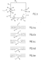
- the switching device 1 As shown in Figure 1, the switching device 1 according to the invention is intended to be placed on the trajectory of objects 2 to be transported, the corresponding installation comprising, at at least partially, several conveyor lines 3, 4.
- these include installations transport by air jet intended, for example, for objects 2 provided with a neck 5.
- said conveyor lines 3, 4 include, in particular, support rails 6 capable of cooperating with said objects 2 at said necks 5, and blowing chambers 7, suitable for allow the projection of an air flow on said objects 2 so as to propel.
- Said switching device 1 allows the transfer, between its entry and exit of said objects 2 from at least one of the conveyor lines to another and / or their passage without changing the conveyor line.
- Said barrel 8 therefore has a prismatic shape, each of its lateral faces 10, 11, 12 being further provided with at least one transfer line 13; 14.15; 16 oriented according to one of the possible referral alternatives for said objects 2.
- the barrel 8 has four side faces.
- any prismatic form exhibiting at least three flat side faces could also be used.
- Said faces 10, 12 allowing a change of lines of conveying may also have two transfer lines, so provided in Y, to authorize, in addition, a passage without line change for one of the conveyor lines 2, 3.
- the longitudinal axis 9 of said barrel 8 is, in particular, intended to be oriented substantially parallel to the conveyor lines 3, 4 and as illustrated in figure 1, is above these latter i.e. on the side opposite to the path of the objects 2.
- Each side face 10, 11, 12 has, for example, a dimension greater than the distance between the conveyor lines 3, 4 in input and / or output of said switching device 1.
- said barrel 8 is provided with a substantially square section, a first 11 of its side faces allowing passage without changing the line of conveying, a second 12 allowing the passage of one of the lines 4 of conveying, known as the right lane, to the other lane 3 conveying, known as the left lane, third 10 allowing the passage from said left queue 3 to said right queue 4.
- said barrel 8 may also present a triangular section, all the possibilities switch then also being filled in the case of an installation comprising, as shown, two conveyor lines 3, 4 at the inlet and at the output of said device 1.
- a quadrangular section has the advantage of offering an additional face that can be equipped according to the structure of the installation in which said switching device 1 is inserted.
- Said first face 11 is, for example, between said second and third faces 12, 10.
- Said first face 11 has, in particular, two lines of transfer 14, 15, parallel to each other.
- the said second 12 and third 10 side faces they each have a transfer line 13, 16 connecting the conveyor lines 3, 4 concerned in a direction substantially parallel to the diagonal of the corresponding side face 10, 12 of the barrel 8.
- each transfer line 13; 14, 15; 16 consists, for example of a channel 17 able to accommodate one end 5 of said objects 2, and a support rail 18, provided under said channel 17, capable of cooperating with said end 5.
- Said switching device 1 further comprises optionally, at least at the level of said transfer lines 13; 14, 15; 16 lateral guides, not shown.
- the latter have the function, in particular, to improve the guidance of the objects transported. In case of use, they give said barrel 8, in a way the appearance of a hedgehog.
- said referral device 1 comprises, upstream and downstream of said barrel 8, a circulation chamber 19, 20 capable of promoting the interface between said barrel 8 and said lines of conveying 3, 4, and this in particular depending on the structure of the installation used.
- Said circulation chambers 19, 20 and said barrel 8 are, for example, of the same section and / or in the extension of each other when said barrel 8 is in position, said circulation chambers 19, 20 being provided fixed, that is to say not rotating unlike said barrel 8.
- Said circulation chambers 19, 20 are naturally provided with lines for conveying objects 2, in particular in the extension straight of said conveyor lines 3, 4 of the installation in which said device 1 is inserted.
- transfer lines 13; 14, 15; 16 they have, for example, a structure formed by a channel and a support rail.
- Said circulation chambers 19, 20 may furthermore, possibly also be provided with lateral guides for the objects 2.
- said switching device 1 is provided, for example, an electric motor, not shown, capable of driving said barrel 8 into rotation.
- the switching device according to the invention can also have more than two conveyor lines at the inlet and exit.
- it is an installation comprising three conveying lines in input and output.
- the barrel 8 comprises, for example, five side faces so as to allow all possible alternatives to the right.
- the invention also relates to a transport installation by air jet of objects 2 such as, in particular, bottles, flasks or the like, equipped with a switching device 1 as presented above.
- an installation comprising support rails 6, able to cooperate with said objects 2 along its conveyor lines 3, 4, and blowing chambers 7 able to allow the projection of an air flow on said objects 2 so as to propel them along said lines of conveying 3, 4.
- said blowing chambers 7 are arranged above said support rails 6. From more, said blowing chambers 7 have channels 21 in which one end 5 of said objects 2 can circulate under the action of air jet from said blowing chambers 7 through slots, not shown, formed on the walls of said channels 17.
- said support rails 6 are located under said channels 21 and consist, in particular, of two ramps 22, 23 located on each side of said corresponding channels 21.
- Such facilities can be used to transport objects 2 having, for example, a protuberance 24 at their neck 5, said neck 5 circulating in said channel 21 and said protuberance 24 cooperating with said ramps 22, 23.
- the rails supports 6, 18 of said installation and of said switching device 1 are provided in the extension of each other as well as said channels 21, 17.
- said channels 17 of the switching device 1 are provided, optionally, slots allowing the propulsion of air jets on objects 2 while said support rails 18 of said switching device 1 consist of two ramps provided on each side of said channels 17, and this as well for said barrel as, where appropriate, for said circulation chambers 19, 20.
- said switching device 1 in the installation of air jet transport described is thus optimized.
- said circulation chambers 19, 20 are particularly helpful. Indeed, they promote a tight junction between said chambers blowing 7 of the conveyor lines 3, 4 and said barrel 8.
- the transport of objects 2 during referral is thus favored with a minimum of loss air.
- a wind tunnel not shown, could be provided, for example on a free face 25 of said barrel 8.
- said face 25 can, according to another mode of realization, present transfer lines, according to one of the alternatives possible referrals, possibly redundant compared to alternatives already present on the other faces 10, 11, 12.
- guides side not shown can also be provided along the lines of conveying 3, 4 of said installation.
Landscapes
- Engineering & Computer Science (AREA)
- Physics & Mathematics (AREA)
- Mechanical Engineering (AREA)
- Fluid Mechanics (AREA)
- Acoustics & Sound (AREA)
- Health & Medical Sciences (AREA)
- Audiology, Speech & Language Pathology (AREA)
- Human Computer Interaction (AREA)
- Signal Processing (AREA)
- Multimedia (AREA)
- Computational Linguistics (AREA)
- Spectroscopy & Molecular Physics (AREA)
- Branching, Merging, And Special Transfer Between Conveyors (AREA)
- Supplying Of Containers To The Packaging Station (AREA)
- Vending Machines For Individual Products (AREA)
- Wrapping Of Specific Fragile Articles (AREA)
Claims (10)
- Aufspaltungsvorrichtung (1) für Anlage zur Beförderung von Gegenständen (2), wie nämlich Flaschen, Fläschchen oder dergleichen, umfassend, wenigstens zum Teil, mehrere Beförderungsbahnen (3, 4) für die genannten Gegenstände (2), wobei die genannte Aufspaltungsvorrichtung (1), die auf den Weg der genannten Gegenstände (2) anzubringen ist, geeignet ist, deren Übergang, zwischen dem Eingang und dem Ausgang der genannten Vorrichtung (1), wenigstens von einer der Beförderungsbahnen auf eine andere und/oder deren Durchgang ohne Beförderungsbahnwechslung, zu erlauben, dadurch gekennzeichnet, daß sie aus einer im Querschnitt vieleckigen Schleuse (8) besteht, die geeignet ist, um ihre Längsachse (9) zu schwenken, so daß die abwechselnde Positionierung jeder ihrer Seitenflächen (10, 11, 12) in der Verlängerung der genannten Beförderungsbahnen (3, 4) erlaubt wird, wobei die genannten Seitenflächen (10, 11, 12) jeweils mit wenigstens einer Übergangsbahn (13 ; 14, 15 ; 16) versehen ist, die einer der möglichen Aufspaltungsalternativen für die genannten Gegenstände (2) entsprechend orientiert ist.
- Vorrichtung nach Anspruch 1, bei der die Längsachse (9) der genannten Schleuse (8) dazu bestimmt ist, im wesentlichen parallel zu den Beförderungsbahnen (3, 4) orientiert zu werden.
- Vorrichtung nach Anspruch 1, bei der die Längsachse (9) der genannten Schleuse (8) dazu bestimmt ist, sich oberhalb der genannten Beförderungsbahnen (3, 4) orientiert zu befinden.
- Vorrichtung nach Anspruch 1, bei der jede Seitenfläche (10, 11, 12) eine größere Abmessung aufweist als der am Eingang und/oder am Ausgang zwischen den Beförderungsbahnen (3, 4) vorgesehene Achsenabstand ist.
- Vorrichtung nach Anspruch 1, bei der die genannte Schleuse (8) im Querschnitt im wesentlichen viereckig vorgesehen ist, wobei eine erste (11) ihrer Seitenfläche den Durchgang ohne Beförderungsbahnwechslung erlaubt, eine zweite (12) den Übergang von einer (4) der Beförderungsbahnen, die rechte Bahn genannt wird, auf die andere Beförderungsbahn (3), die linke Bahn genannt wird, erlaubt, eine dritte (10) den Übergang von der genannten linken Bahn (3) auf die genannte rechte Bahn erlaubt.
- Vorrichtung nach Anspruch 5, bei der die genannte erste Fläche (11) zwei parallel zu einander und/oder in der geradlinigen Verlängerung jeder der entsprechenden Beförderungsbahnen (3, 4) verlaufende Übertragungsbahnen (14, 15) aufweist und/oder die genannte zweite (12) und dritte (10) Seitenfläche je eine Übertragungsbahn (13, 16) aufweist, die die betreffenden Beförderungsbahnen (3, 4) in einer Richtung im wesentlichen parallel zur Diagonale der entsprechenden Seitenfläche (12, 10) der genannten Schleuse (8) verbindet.
- Vorrichtung nach Anspruch 1, bei der jede Übertragungsbahn (13 ; 14, 15 ; 16) aus einem Kanal (17), geeignet, ein Ende (5) der genannten Gegenstände (2) aufzunehmen, und einer unterhalb des genannten Kanals (17) vorgesehenen Tragschiene (18), geeignet, mit dem genannten Ende (5) zusammenzuwirken, besteht.
- Vorrichtung nach Anspruch 1, umfassend außerdem, wenigstens im Bereich der genannten Übertragungsbahnen (13 ; 14, 15 ; 16), Seitenführungen.
- Vorrichtung nach Anspruch 1, umfassend außerdem, stromauf- und -abwärts der genannten Schleuse (8), eine Umlaufkammer (19, 20), geeignet, die Schnittstelle zwischen der genannten Schleuse (8) und den genannten Beförderungsbahnen (3, 4) zu fördern.
- Lufistrahl-Beförderungsanlage für Gegenstände (2), wie Flaschen, Fläschchen oder dergleichen, ausgerüstet mit einer Aufspaltungsvorrichtung nach Anspruch 1.
Applications Claiming Priority (3)
| Application Number | Priority Date | Filing Date | Title |
|---|---|---|---|
| FR9704514 | 1997-04-08 | ||
| FR9704514A FR2761671B1 (fr) | 1997-04-08 | 1997-04-08 | Dispositif d'aiguillage pour installation de transport d'objets tels que, notamment, bouteilles, flacons ou autres et installation de transport par jet d'air equipee d'un tel dispositif |
| PCT/FR1998/000716 WO1998045196A1 (fr) | 1997-04-08 | 1998-04-08 | Dispositif d'aiguillage pour installation de transport d'objets |
Publications (2)
| Publication Number | Publication Date |
|---|---|
| EP0973683A1 EP0973683A1 (de) | 2000-01-26 |
| EP0973683B1 true EP0973683B1 (de) | 2002-02-20 |
Family
ID=9505831
Family Applications (1)
| Application Number | Title | Priority Date | Filing Date |
|---|---|---|---|
| EP98920594A Expired - Lifetime EP0973683B1 (de) | 1997-04-08 | 1998-04-08 | Weichenanordnung für eine transportanlage für gegenständen |
Country Status (12)
| Country | Link |
|---|---|
| US (1) | US6257805B1 (de) |
| EP (1) | EP0973683B1 (de) |
| JP (1) | JP2001518864A (de) |
| KR (1) | KR100339058B1 (de) |
| CN (1) | CN1097012C (de) |
| AT (1) | ATE213484T1 (de) |
| AU (1) | AU737476B2 (de) |
| BR (1) | BR9807923A (de) |
| CA (1) | CA2284875C (de) |
| DE (1) | DE69803921T2 (de) |
| FR (1) | FR2761671B1 (de) |
| WO (1) | WO1998045196A1 (de) |
Families Citing this family (6)
| Publication number | Priority date | Publication date | Assignee | Title |
|---|---|---|---|---|
| FR2824544B1 (fr) * | 2001-05-09 | 2003-10-10 | Netra Systems | Aiguillage a double mouvement de translation et rotation pour installation de convoyage par jets d'air |
| DE10162827A1 (de) * | 2001-12-20 | 2003-10-02 | Krones Ag | Weichenvorrichtung für Luftförderer |
| WO2007147005A2 (en) * | 2006-06-13 | 2007-12-21 | Arrowhead Conveyor Corporation, Inc. | Conveyor apparatus |
| DE102007023219A1 (de) * | 2007-05-18 | 2008-11-20 | Siemens Ag | Fluggepäckförderanlage |
| US7997405B2 (en) | 2009-07-22 | 2011-08-16 | Arrowhead Systems, Inc. | Sanitary conveyor |
| WO2015024936A1 (de) * | 2013-08-23 | 2015-02-26 | Siemens Aktiengesellschaft | Weichenanordnung für eine stückgutförderanlage |
Family Cites Families (3)
| Publication number | Priority date | Publication date | Assignee | Title |
|---|---|---|---|---|
| FR886656A (fr) * | 1942-06-06 | 1943-10-21 | Lamson Ets | Perfectionnement à l'équipement des lignes pneumatiques |
| US5100265A (en) * | 1991-01-22 | 1992-03-31 | Jetstream Systems, Inc. | Rotatable changeover parts for conveyor system |
| DE69400095T2 (de) * | 1993-10-22 | 1996-07-25 | Neu Trans System Sa | Drehtischweiche für eine pneumatische Fördervorrichtung von Behältern |
-
1997
- 1997-04-08 FR FR9704514A patent/FR2761671B1/fr not_active Expired - Fee Related
-
1998
- 1998-04-08 AU AU73401/98A patent/AU737476B2/en not_active Ceased
- 1998-04-08 EP EP98920594A patent/EP0973683B1/de not_active Expired - Lifetime
- 1998-04-08 JP JP54246598A patent/JP2001518864A/ja active Pending
- 1998-04-08 CN CN98804004A patent/CN1097012C/zh not_active Expired - Fee Related
- 1998-04-08 DE DE69803921T patent/DE69803921T2/de not_active Expired - Fee Related
- 1998-04-08 WO PCT/FR1998/000716 patent/WO1998045196A1/fr not_active Ceased
- 1998-04-08 BR BR9807923-9A patent/BR9807923A/pt active Search and Examination
- 1998-04-08 CA CA002284875A patent/CA2284875C/fr not_active Expired - Fee Related
- 1998-04-08 KR KR1019997008650A patent/KR100339058B1/ko not_active Expired - Fee Related
- 1998-04-08 AT AT98920594T patent/ATE213484T1/de not_active IP Right Cessation
- 1998-04-08 US US09/402,718 patent/US6257805B1/en not_active Expired - Fee Related
Also Published As
| Publication number | Publication date |
|---|---|
| CN1097012C (zh) | 2002-12-25 |
| EP0973683A1 (de) | 2000-01-26 |
| DE69803921T2 (de) | 2003-01-16 |
| KR20010005587A (ko) | 2001-01-15 |
| KR100339058B1 (ko) | 2002-05-31 |
| ATE213484T1 (de) | 2002-03-15 |
| FR2761671A1 (fr) | 1998-10-09 |
| WO1998045196A1 (fr) | 1998-10-15 |
| FR2761671B1 (fr) | 1999-06-11 |
| AU737476B2 (en) | 2001-08-23 |
| JP2001518864A (ja) | 2001-10-16 |
| CA2284875A1 (fr) | 1998-10-15 |
| AU7340198A (en) | 1998-10-30 |
| US6257805B1 (en) | 2001-07-10 |
| BR9807923A (pt) | 2000-02-22 |
| CA2284875C (fr) | 2003-07-01 |
| CN1252036A (zh) | 2000-05-03 |
| DE69803921D1 (de) | 2002-03-28 |
Similar Documents
| Publication | Publication Date | Title |
|---|---|---|
| EP0947761B1 (de) | Signalleuchte mit mehreren Lichtquellen | |
| EP0973683B1 (de) | Weichenanordnung für eine transportanlage für gegenständen | |
| EP0126056A1 (de) | Sitzinneneinrichtung für den Rumpf eines Flugzeuges | |
| FR2860280A1 (fr) | Phare de vehicule a lampes a elements photoemissifs | |
| WO2014049082A1 (fr) | Guide de lumière pour un dispositif d'éclairage et/ou de signalisation de véhicule automobile | |
| CA2511432C (fr) | Inverseur de poussee a grilles de deflection optimisees | |
| EP0466605A1 (de) | Reflektor für eine Beleuchtungsvorrichtung eines Fahrzeuges und Scheinwerfer und Signalleuchte mit solchem Reflektor | |
| CA2693091A1 (fr) | Chaine porteuse de cables pour volet mobile de bord d'attaque d'une aile d'aeronef | |
| EP3398885B1 (de) | Ausrüstung zum sortieren von objekten für eine logistik-plattform | |
| FR2925919A1 (fr) | Dispositif de soufflage de gaz sur une face d'un materiau en bande en defilement | |
| FR3048196A1 (fr) | Dispositif de separation pour moule comprenant une chaine de maillons articules entre eux | |
| FR3030684A1 (fr) | Dispositif lumineux comprenant des sources surfaciques de lumiere | |
| EP1031386B1 (de) | Ausgangsrutsche in eine Sortiereinrichtung | |
| EP1568607A1 (de) | Sitzanordnung für Flugzeugkabine | |
| EP2800927A1 (de) | Lichtleiter und fahrzeug mit einem lichtleiter | |
| EP1089904B1 (de) | Sessellift mit verbessertem einstieg | |
| FR2803835A1 (fr) | Procede et dispositif de convoyage d'objets en position suspendue | |
| EP1739468A1 (de) | Lichtwellenleiterstecker | |
| FR2468499A1 (fr) | Systeme propulsif pour un navire a helice, et navire ainsi equipe | |
| EP0072310B1 (de) | Sortiersystem mit grosser Durchgangsleistung | |
| FR2753784A1 (fr) | Dispositif d'alimentation en munitions d'une arme montee sur aeronef, equipe d'un tel dispositif | |
| FR2712635A1 (fr) | Inverseur de poussée à portes pour moteur d'avion équipé de systèmes de sécurité interdisant l'ouverture intempestive des portes. | |
| WO1999052802A1 (fr) | Dispositif de convoyage d'objets par soufflage et element definissant au moins une portion longitudinale de la chambre de soufflage dudit dispositif | |
| CH684549A5 (fr) | Aile galbée déployable pour engin volant. | |
| FR2620400A1 (fr) | Chariot transporteur et convoyeur |
Legal Events
| Date | Code | Title | Description |
|---|---|---|---|
| PUAI | Public reference made under article 153(3) epc to a published international application that has entered the european phase |
Free format text: ORIGINAL CODE: 0009012 |
|
| 17P | Request for examination filed |
Effective date: 19990913 |
|
| AK | Designated contracting states |
Kind code of ref document: A1 Designated state(s): AT BE CH CY DE DK ES FI FR GB GR IE IT LI LU MC NL PT SE |
|
| GRAG | Despatch of communication of intention to grant |
Free format text: ORIGINAL CODE: EPIDOS AGRA |
|
| 17Q | First examination report despatched |
Effective date: 20010425 |
|
| GRAG | Despatch of communication of intention to grant |
Free format text: ORIGINAL CODE: EPIDOS AGRA |
|
| GRAH | Despatch of communication of intention to grant a patent |
Free format text: ORIGINAL CODE: EPIDOS IGRA |
|
| GRAH | Despatch of communication of intention to grant a patent |
Free format text: ORIGINAL CODE: EPIDOS IGRA |
|
| REG | Reference to a national code |
Ref country code: GB Ref legal event code: IF02 |
|
| GRAA | (expected) grant |
Free format text: ORIGINAL CODE: 0009210 |
|
| AK | Designated contracting states |
Kind code of ref document: B1 Designated state(s): AT BE CH CY DE DK ES FI FR GB GR IE IT LI LU MC NL PT SE |
|
| PG25 | Lapsed in a contracting state [announced via postgrant information from national office to epo] |
Ref country code: NL Free format text: LAPSE BECAUSE OF FAILURE TO SUBMIT A TRANSLATION OF THE DESCRIPTION OR TO PAY THE FEE WITHIN THE PRESCRIBED TIME-LIMIT Effective date: 20020220 Ref country code: IE Free format text: LAPSE BECAUSE OF FAILURE TO SUBMIT A TRANSLATION OF THE DESCRIPTION OR TO PAY THE FEE WITHIN THE PRESCRIBED TIME-LIMIT Effective date: 20020220 Ref country code: GR Free format text: LAPSE BECAUSE OF FAILURE TO SUBMIT A TRANSLATION OF THE DESCRIPTION OR TO PAY THE FEE WITHIN THE PRESCRIBED TIME-LIMIT Effective date: 20020220 Ref country code: GB Free format text: LAPSE BECAUSE OF FAILURE TO SUBMIT A TRANSLATION OF THE DESCRIPTION OR TO PAY THE FEE WITHIN THE PRESCRIBED TIME-LIMIT Effective date: 20020220 Ref country code: FI Free format text: LAPSE BECAUSE OF FAILURE TO SUBMIT A TRANSLATION OF THE DESCRIPTION OR TO PAY THE FEE WITHIN THE PRESCRIBED TIME-LIMIT Effective date: 20020220 Ref country code: AT Free format text: LAPSE BECAUSE OF FAILURE TO SUBMIT A TRANSLATION OF THE DESCRIPTION OR TO PAY THE FEE WITHIN THE PRESCRIBED TIME-LIMIT Effective date: 20020220 |
|
| REF | Corresponds to: |
Ref document number: 213484 Country of ref document: AT Date of ref document: 20020315 Kind code of ref document: T |
|
| REG | Reference to a national code |
Ref country code: CH Ref legal event code: EP |
|
| REF | Corresponds to: |
Ref document number: 69803921 Country of ref document: DE Date of ref document: 20020328 |
|
| PG25 | Lapsed in a contracting state [announced via postgrant information from national office to epo] |
Ref country code: MC Free format text: LAPSE BECAUSE OF NON-PAYMENT OF DUE FEES Effective date: 20020408 Ref country code: LU Free format text: LAPSE BECAUSE OF NON-PAYMENT OF DUE FEES Effective date: 20020408 |
|
| PG25 | Lapsed in a contracting state [announced via postgrant information from national office to epo] |
Ref country code: CY Free format text: LAPSE BECAUSE OF FAILURE TO SUBMIT A TRANSLATION OF THE DESCRIPTION OR TO PAY THE FEE WITHIN THE PRESCRIBED TIME-LIMIT Effective date: 20020430 Ref country code: BE Free format text: LAPSE BECAUSE OF NON-PAYMENT OF DUE FEES Effective date: 20020430 |
|
| PG25 | Lapsed in a contracting state [announced via postgrant information from national office to epo] |
Ref country code: PT Free format text: LAPSE BECAUSE OF FAILURE TO SUBMIT A TRANSLATION OF THE DESCRIPTION OR TO PAY THE FEE WITHIN THE PRESCRIBED TIME-LIMIT Effective date: 20020520 Ref country code: DK Free format text: LAPSE BECAUSE OF FAILURE TO SUBMIT A TRANSLATION OF THE DESCRIPTION OR TO PAY THE FEE WITHIN THE PRESCRIBED TIME-LIMIT Effective date: 20020520 |
|
| NLV1 | Nl: lapsed or annulled due to failure to fulfill the requirements of art. 29p and 29m of the patents act | ||
| GBV | Gb: ep patent (uk) treated as always having been void in accordance with gb section 77(7)/1977 [no translation filed] |
Effective date: 20020220 |
|
| PG25 | Lapsed in a contracting state [announced via postgrant information from national office to epo] |
Ref country code: ES Free format text: LAPSE BECAUSE OF FAILURE TO SUBMIT A TRANSLATION OF THE DESCRIPTION OR TO PAY THE FEE WITHIN THE PRESCRIBED TIME-LIMIT Effective date: 20020829 |
|
| REG | Reference to a national code |
Ref country code: CH Ref legal event code: NV Representative=s name: ISLER & PEDRAZZINI AG |
|
| REG | Reference to a national code |
Ref country code: IE Ref legal event code: FD4D |
|
| PLBE | No opposition filed within time limit |
Free format text: ORIGINAL CODE: 0009261 |
|
| STAA | Information on the status of an ep patent application or granted ep patent |
Free format text: STATUS: NO OPPOSITION FILED WITHIN TIME LIMIT |
|
| 26N | No opposition filed |
Effective date: 20021121 |
|
| PGFP | Annual fee paid to national office [announced via postgrant information from national office to epo] |
Ref country code: FR Payment date: 20040427 Year of fee payment: 7 |
|
| PGFP | Annual fee paid to national office [announced via postgrant information from national office to epo] |
Ref country code: CH Payment date: 20050323 Year of fee payment: 8 Ref country code: SE Payment date: 20050323 Year of fee payment: 8 |
|
| PGFP | Annual fee paid to national office [announced via postgrant information from national office to epo] |
Ref country code: DE Payment date: 20050401 Year of fee payment: 8 |
|
| PG25 | Lapsed in a contracting state [announced via postgrant information from national office to epo] |
Ref country code: FR Free format text: LAPSE BECAUSE OF NON-PAYMENT OF DUE FEES Effective date: 20051230 |
|
| REG | Reference to a national code |
Ref country code: FR Ref legal event code: ST Effective date: 20051230 |
|
| PG25 | Lapsed in a contracting state [announced via postgrant information from national office to epo] |
Ref country code: SE Free format text: LAPSE BECAUSE OF NON-PAYMENT OF DUE FEES Effective date: 20060409 |
|
| PG25 | Lapsed in a contracting state [announced via postgrant information from national office to epo] |
Ref country code: LI Free format text: LAPSE BECAUSE OF NON-PAYMENT OF DUE FEES Effective date: 20060430 Ref country code: CH Free format text: LAPSE BECAUSE OF NON-PAYMENT OF DUE FEES Effective date: 20060430 |
|
| PGFP | Annual fee paid to national office [announced via postgrant information from national office to epo] |
Ref country code: IT Payment date: 20060430 Year of fee payment: 9 |
|
| PG25 | Lapsed in a contracting state [announced via postgrant information from national office to epo] |
Ref country code: DE Free format text: LAPSE BECAUSE OF NON-PAYMENT OF DUE FEES Effective date: 20061101 |
|
| REG | Reference to a national code |
Ref country code: CH Ref legal event code: PL |
|
| EUG | Se: european patent has lapsed | ||
| PG25 | Lapsed in a contracting state [announced via postgrant information from national office to epo] |
Ref country code: IT Free format text: LAPSE BECAUSE OF NON-PAYMENT OF DUE FEES Effective date: 20070408 |