EP0974183B1 - Rotor pour machine electrique tournante, notamment machine a flux transversal - Google Patents
Rotor pour machine electrique tournante, notamment machine a flux transversal Download PDFInfo
- Publication number
- EP0974183B1 EP0974183B1 EP98916939A EP98916939A EP0974183B1 EP 0974183 B1 EP0974183 B1 EP 0974183B1 EP 98916939 A EP98916939 A EP 98916939A EP 98916939 A EP98916939 A EP 98916939A EP 0974183 B1 EP0974183 B1 EP 0974183B1
- Authority
- EP
- European Patent Office
- Prior art keywords
- magnet
- soft iron
- elements
- rotor
- circumferential direction
- Prior art date
- Legal status (The legal status is an assumption and is not a legal conclusion. Google has not performed a legal analysis and makes no representation as to the accuracy of the status listed.)
- Expired - Lifetime
Links
- XEEYBQQBJWHFJM-UHFFFAOYSA-N Iron Chemical compound [Fe] XEEYBQQBJWHFJM-UHFFFAOYSA-N 0.000 claims abstract description 177
- 229910052742 iron Inorganic materials 0.000 claims abstract description 67
- 239000012811 non-conductive material Substances 0.000 claims abstract description 5
- 230000004907 flux Effects 0.000 claims description 7
- 230000000295 complement effect Effects 0.000 claims description 4
- 239000000696 magnetic material Substances 0.000 claims 1
- 230000002093 peripheral effect Effects 0.000 abstract 2
- 230000000712 assembly Effects 0.000 description 6
- 238000000429 assembly Methods 0.000 description 6
- 230000006378 damage Effects 0.000 description 5
- 238000010438 heat treatment Methods 0.000 description 4
- 229910052751 metal Inorganic materials 0.000 description 4
- 238000009413 insulation Methods 0.000 description 3
- 238000004519 manufacturing process Methods 0.000 description 3
- 239000000463 material Substances 0.000 description 3
- 239000000853 adhesive Substances 0.000 description 2
- 230000001070 adhesive effect Effects 0.000 description 2
- 150000001875 compounds Chemical class 0.000 description 2
- 230000000694 effects Effects 0.000 description 2
- 230000003685 thermal hair damage Effects 0.000 description 2
- 238000010521 absorption reaction Methods 0.000 description 1
- 238000004026 adhesive bonding Methods 0.000 description 1
- 238000004873 anchoring Methods 0.000 description 1
- 230000004888 barrier function Effects 0.000 description 1
- 238000005266 casting Methods 0.000 description 1
- 239000002131 composite material Substances 0.000 description 1
- 230000005347 demagnetization Effects 0.000 description 1
- 238000006073 displacement reaction Methods 0.000 description 1
- 230000001771 impaired effect Effects 0.000 description 1
- 239000002184 metal Substances 0.000 description 1
- 210000004508 polar body Anatomy 0.000 description 1
- 238000004382 potting Methods 0.000 description 1
Images

Classifications
-
- H—ELECTRICITY
- H02—GENERATION; CONVERSION OR DISTRIBUTION OF ELECTRIC POWER
- H02K—DYNAMO-ELECTRIC MACHINES
- H02K1/00—Details of the magnetic circuit
- H02K1/06—Details of the magnetic circuit characterised by the shape, form or construction
- H02K1/22—Rotating parts of the magnetic circuit
- H02K1/27—Rotor cores with permanent magnets
Definitions
- the invention relates to a rotor for an electrical machine, in particular a transverse flux machine, in detail with the features from the Preamble of claim 1.
- the rotor of a transverse flux machine comprises one or more axially lined up, by interposed plastic or other, electrically non-conductive material rings and / or a Rotor disc separate, concentric rings (active rings), in to the so-called collectors or Soft iron elements, which are usually made of axially stacked Electrical sheet can be constructed, and magnets are arranged.
- This Concentric rings are also called a pole structure.
- the rotor design described in DE 92 00 116 U1 has collector or.
- Soft iron elements on their magnet assemblies facing sides in the circumferential direction with U-shaped recesses are provided, in which the magnets are inserted.
- Recesses are formed two protrusions, which the Partially encompass the magnet arrangement.
- the width of the recess or its Dimension in the radial direction is slightly larger than the jacket length I, i.e. the dimension of the magnet arrangement in the radial direction.
- EP 0 642 204 A1 discloses an embodiment in which the rotor is axially attachable to the rotor axis Has rotor disc on which the polarized magnets and magnetizable collector or soft iron elements each in one concentric ring assembly are attached, the attachment with Fasteners are made by the polarized magnets, which at least in the arrangement area of the fastening elements in two parts are executed, go through and on the rotor disk or on an in Insulating ring element connected to the rotor disk in the axial direction are attached.
- the magnet arrangements with the neighboring ones Collector or soft iron elements form-fitting in the circumferential direction and / or cohesively connected.
- a disadvantage of such arrangements is that provided only positive connections between the magnets of the magnet arrangement and the neighboring collector or soft iron elements in Circumferential direction due to the centrifugal forces occurring during operation of the rotor even with simultaneous fixation of the collector or soft iron elements compared to the elements in the axial direction in the radial Direction, such as end ring, intermediate ring and carrier plate, the Magnet arrangements are pressed against the radially outer projections and an electrically conductive connection between collector or Soft iron elements and the magnet arrangement allow what a undesirable high heating of the rotor can result. In doing so also the magnets are stressed by the heat conduction and in their magnetic properties impaired what to the complete Demagnetization of the magnets can result.
- the invention is therefore based on the object of a rotor to further develop electrical machine such that the disadvantages mentioned be avoided.
- the rotor strength should be maintained Rotors of the type mentioned with a positive connection between collector or soft iron elements and magnet arrangements Failure of the insulation layer the additional losses, which is a strong one Heating of the rotor and the magnetic properties of the magnets can be avoided.
- the constructive and manufacturing expenditure is to be kept as low as possible.
- a support of the magnet arrangement under centrifugal force is thus applied this projection, which essentially serves for pre-centering avoided, which also means that on the collector or soft iron element provided insulation layer in this area from damage becomes.
- the risk of making a conductive connection between two, by a magnet arrangement separated collector or Soft iron elements can thus be almost completely ruled out because damage to the elements on the collector or soft iron applied insulating layer due to high mechanical stress, for example, when supporting the magnet arrangements via this Insulating layer on the stop surface, which leads to damage and so that the establishment of a conductive connection can result in remains essentially limited to this area and the contact areas of the Magnet arrangements in the circumferential direction on the adjacent collector or.
- Soft iron elements not this enormously high load are exposed, causing damage to the between magnet assembly and collector or soft iron element provided insulating layer in this Area is excluded as far as possible.
- the solution according to the invention ensures that the forces acting on a magnet arrangement or the individual magnets of a magnet arrangement preferably uniformly in the radial direction in each case only on one of the two collector or soft iron elements adjacent to the magnet arrangement, in particular on the stop surface provided for this collector - or soft iron element are supported.
- the inventors have recognized that due to the centrifugal force in the solutions known from the prior art, the magnet arrangements in the radial direction against the collector or soft iron elements directly adjacent to the magnet arrangements in the region of their outer diameter against the projections formed essentially in the circumferential direction, which each enclose a part of the magnet arrangement in the circumferential direction and form a stop for the magnet arrangements in the radial direction.
- the solution according to the invention does not require that the second of the Magnet arrangement adjacent collector and soft iron elements in the Be completely free of a protrusion in the area of its outer diameter got to.
- a lead to pre-centering is conceivable, but this is up to arrange a diameter on which in the direction of the rotor axis facing surface of the projection in normal operation of the electrical Machine, especially the transverse flux machine, not as Stop surface takes effect.
- the individual collector or soft iron elements are preferably made of axially layered sheet metal elements built.
- the tabs will be preferably formed by U-shaped recesses.
- the collector or soft iron elements are then in the circumferential direction preferably arranged such that their respective trained End faces are aligned identically in the circumferential direction, i.e. each in the point in the same direction.
- the orientation of the end faces with the stop surface can either be circumferential against the direction of rotation or in the direction of rotation. Preferably the alignment is always in one direction.
- Collector or soft iron element types - a first collector or Soft iron element type and a second collector or Soft iron element type - to be provided in the rotor, which alternately in Are arranged circumferentially between the magnet assemblies.
- Every collector or Soft iron element of the first type forms in the area its two to the neighboring magnet arrangements in the circumferential direction facing end faces each have a radially outer stop surface Support the magnet assembly in the radial direction during each Collector or soft iron element of the second type in the area of its both to the neighboring magnet arrangements in the circumferential direction facing end faces free of a radially outer stop surface Support of the magnet arrangement is.
- Each of the collectors or For this purpose, soft iron elements are preferably radial
- the direction of the symmetry line in the installed position is symmetrical. Thermal damage can also occur with such a solution can be avoided since a conductive connection does not have a large number of Magnet arrangements and collector or soft iron elements in Circumferential direction can be produced due to the locking effect of missing stop surfaces on the collector or soft iron elements.
- the magnet arrangements can be constructed in one piece or else each include at least one inner and one outer magnet. in the latter case are at least two in succession in the radial direction Arranged magnets. In the radial direction one after the other arranged magnets has the one lying in the radial direction inside Internal magnet in the radial direction and preferably also in the circumferential direction smaller dimensions than the external magnet.
- Other Embodiments are conceivable.
- the individual magnets of the magnet arrangements can be in the radial direction be designed differently in terms of their cross-section, i.e. the Use, for example, rectangular or trapezoidal cross sections possible.
- a connecting element to magnet arrangements, which at least the positive connection between the individual rows alternately arranged collector and soft iron elements with intermediate magnet arrangements in the axial direction, i.e. with the the rows immediately adjacent rings, for example end ring, Intermediate ring and / or carrier disc, is used.
- the arrangement of the Connecting element can with one-piece design of the magnet above and / or below this in the radial direction.
- This connecting element becomes an inner and an outer magnet preferably arranged between the inner and outer magnets because such an arrangement a fixation of the individual magnets - inside and External magnet - guaranteed in the radial direction.
- the rows from in Circumferential direction with alternately magnetized magnet arrangements intermediate collector or Soft iron elements are in Circumferential direction at certain intervals in the axial direction on both sides protruding elements assigned.
- the protruding elements are in complementary grooves on the separate rows from in Circumferential direction with alternately magnetized magnet arrangements intermediate collector or Soft iron elements neighboring Rings - end ring, intermediate ring and central carrier disc - insertable.
- These connecting elements with the elements protruding on both sides are preferably in the form of one made of an amagnetic material Intermediate plate executed. Regarding the concrete execution, the Application DE 196 10 754. referred, the disclosure content fully extensively included in the disclosure content of this application becomes.
- These connecting elements, in particular intermediate plates can additionally also a conductive connection between two one Form magnet arrangement adjacent collector or soft iron elements.
- these intermediate elements can preferably be in uniform and certain distances either of each magnet arrangement or a variety, but not all magnet assemblies become.
- the magnet assemblies are preferred executed such that, in particular in the case of designs with at least one Inside and an outside magnet leading to the non-stop end faces facing end face of the magnet arrangement no projections or Has recesses, which in turn additional contact surfaces for the would form collector or soft iron elements.
- this also applies for the design and arrangement of the intermediate plate or positive connection element. This extends ibn
- the circumferential direction is only a maximum corresponding to the extension of the Magnet arrangement in the circumferential direction.
- the radially outer stop surface for the magnet arrangement is preferred arranged in the area of the outer diameter of the magnet arrangements, because in this case the entire magnet arrangement in the positive Connection can be integrated. Arrangements of the radially outer Stop surface in the area of the end faces of the collector or Soft iron elements in the radial direction, i.e. the radially outer The stop surface for the magnet arrangement is larger on one diameter than the inside diameter of the magnet assembly and in the area of the Extent of the magnet arrangement arranged in the radial direction, are also conceivable, but in this case part of the Magnet arrangement excluded from the positive connection.
- the changes are preferably to implement a one-sided Force applied to the collector or soft iron elements.
- a one-sided Force applied to the collector or soft iron elements it is theoretically also conceivable to meet the requirements to create appropriate design of the magnets, however this is Very expensive to manufacture and there are increased eddy current losses expected.
- the individual pole structures comprise at least two juxtaposed, by an intermediate layer of magnetic and electrically non-conductive material, which is also referred to as an intermediate ring, separate rows of alternately magnetized in the circumferential direction Magnet arrangements with intermediate collector or. Soft iron elements.
- the rotors designed according to the invention are for any type of electrical machines, in particular transverse flux machines used.
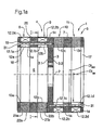
- FIG. 1 a is used to explain the basic structure permitted rotor an axial section through a rotor 1 is simplified.
- the rotor 1 further comprises a, on the rotor shaft rotatably arranged carrier disc 3, on the End faces 3.1 and 3.2 each have an annular coaxial to the rotor axis 2 Pole structure 4 and 5 is arranged.
- Each pole structure 4 and 5 respectively comprises two side by side, through an intermediate layer 6 or 7 magnetically and electrically non-conductive material separate rows 8, 9, or 10, 11 from alternately magnetized in the circumferential direction Permanent magnet arrangements 12, here with 12a and 12b for the rows 8 and 9, and intermediate collector or
- the collector or soft iron elements 13 are preferably from a plurality of one behind the other Executed sheet metal elements, which preferably by means of a casting compound, which also forms an insulating layer on the collector elements, in Be kept in shape. It is also conceivable for the individual sheet metal elements to connect with each other by means of a material bond.
- Each pole structure 4 or 5 has an end ring 16 or 17 on the end face assigned.
- Each magnet arrangement 12 essentially comprises two magnets - An inner magnet 12.1 and an outer magnet 12.2, here representative 12.1a, 12.2a, 12.3a, 12.4a and 12.1b, 12.2b, 12.3b, 12.4b.
- the inner magnet 12.1 is arranged in the radial direction with respect to the rotor axis 2 on a smaller diameter DI IM than the outer magnet 12.2 of each magnet arrangement 12.
- the fixing of the magnets 12.1 or 12.2 in the circumferential direction is essentially carried out by positive locking with the magnet arrangements 12 in Circumferential direction of adjacent collector or soft iron elements 13 as shown in Figure 1b.
- the use of a potting compound or composite, for example in the form of adhesive is conceivable.
- a positive connection element 14 is also assigned to each magnet arrangement 12.
- the form-fitting connecting element 14 is preferably designed as a plate stamped from non-magnetic sheet metal. This extends in the axial direction preferably beyond the axial extent of the magnet arrangement 12.
- the projections 19 and 20 thus formed are assigned essentially complementary grooves 21 and 22 in the elements adjacent to the rings 8, 9, 10 and 11, respectively.
- the connecting elements 14 In the circumferential direction, the connecting elements 14 each extend essentially over the extent of the magnets 12.1 or 12.2 in the circumferential direction.
- the connecting elements 14 are in each magnet arrangement 12 between the inner and the outer magnets 12.1 and 12.2 in the complementary grooves 21 and 22 on the elements adjacent to the magnet arrangements 12 in the axial direction, here the grooves 21a on the end ring 16 and 22a on the intermediate ring 6 and 21b inserted on the intermediate ring 6 and 22b on the carrier disk 3.
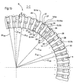
- FIG. 1b illustrates in a simplified representation a view II corresponding to FIG. 1a, ie a view of the end face of the pole structure 4 extending in the circumferential direction, in detail a view of the row 9.
- Each of the collector or soft iron elements 13 adjacent to the magnet arrangements 12 has in FIG radial direction with respect to the rotor axis 2 on a first radially inner stop 24.
- These inner stops 24 are each formed by a projection 25 which is arranged in the region of the inner diameter D IS of a collector or soft iron element 13 on its end faces 26 and 27 which point away from one another in the circumferential direction.
- each magnet arrangement 12 in the radial direction only one outer stop surface is formed for each magnet arrangement 12.
- This external stop or the stop surface is designated 28 and, in the case shown, is arranged in the region of the outer diameter D AS of the collector or soft iron elements 13 on its end face 26 such that when the rotor 1 rotates under centrifugal force, the external magnet, here representative 12.2 bx is supported with its outer end face 30 against the stop 28.
- the outer diameter D AM of the magnet arrangement 12b or the outer magnet 12.2b corresponds to the diameter D IAF of the stop or the stop surface 28.
- At least one of the two collector or soft iron elements 13.1b or 13.2b immediately adjacent in the circumferential direction to a magnet arrangement 12bx, here 13.1b, is free of a second external stop at least on the end face 27 facing the magnet arrangement 12 in the area of the outer diameter D AM of the magnet arrangement 12bx ,
- this freedom is formed by realizing a certain minimum distance a between the outer diameter DAM of the magnet arrangement 12bx and a projection 32.
- the minimum distance a should always be chosen in such a way that support of the magnet arrangement 12bx, in particular the individual magnets 12b.1 or 12b.2, in the radial direction on one of the two adjacent collector or soft iron elements is avoided.
- the collector or soft iron element 13b it is also conceivable for the collector or soft iron element 13b to be designed without an outer projection 32 in the region of the end face 27.
- the Magnet arrangement 12bx adjacent second collector or Soft iron element 13.1b also in the region of its end face 27 Projection 32 on, this projection is only used for pre-centering of the magnet arrangements.
- the individual collector or soft iron elements 13b are to be realized the function is asymmetrical.
- the collectors or soft iron elements are always in the circumferential direction arranged in such a way that the end faces 26 or 27 are always aligned in the same direction in the circumferential direction.
- magnets 12.1b and 12.2b and the intermediate plate 14 are also preferably provided for magnets 12.1b and 12.2b and the intermediate plate 14, the number of stop surfaces and thus the possible vulnerable points of an interruption of the insulation layer in radial Minimize direction. Therefore, the magnet assembly 12bx neighboring non-impact collector or. Soft iron element, here 13.b1 in addition to the radially inner stop 24 no additional contact surface in radial direction for the intermediate plate or the individual magnets intended.
- the entire magnet arrangement 12bx with intermediate plate 14 is located on one surface, while on the opposite collector or Soft iron element 13.2b the end face 26 at least two Partial stop surfaces 33 and 34 forms.
- the form fit takes place between the magnet arrangement 12bx and the collector or soft iron elements mainly with the collector or soft iron element 13.2b.
- FIG. 2 illustrates an embodiment according to the invention for one-sided Force absorption in a view of a polar body structure as in FIG. 1b described for a rotor design with a one-piece design Magnet arrangement 12b.
- the basic structure corresponds to that in FIG. 1 . described
- the same reference numerals are used for the same elements used.
- the magnet arrangement 12b here for illustration 12bx, the two collector or soft iron elements 13.1b and 13.2b are subordinate.
- the collector or soft iron element 13.2b has on its end facing the magnet arrangement 12bx in the area of its outer diameter D AS a projection which forms a stop 28 in the radial direction for the magnet arrangement 12bx.
- the collector or soft iron element 13.1b adjacent to the opposite side of the magnet arrangement is free of an external stop in the radial direction on the end face 27 facing the magnet arrangement in the region of its outer diameter D AS .
- the projection 32 also provided here is arranged at a distance a from the outer diameter D AM .
- the collector or soft iron elements 13 are asymmetrical executed.
- the respective front ends 26 and 27 are of the same design
- the circumferential direction is the same.
Landscapes
- Engineering & Computer Science (AREA)
- Power Engineering (AREA)
- Permanent Field Magnets Of Synchronous Machinery (AREA)
- Synchronous Machinery (AREA)
- Iron Core Of Rotating Electric Machines (AREA)
Claims (13)
- Rotor (1) pour un moteur électrique, en particulier un moteur à flux transversal,caractérisé par les caractéristiques suivantes :1.1 comprenant au moins une structure de bornes (4, 5) ;1.2 la structure de bornes (4, 5) comporte deux rangées (8, 9, 10, 11) juxtaposées, séparées par une couche intermédiaire (6, 7), réalisée dans un matériau magnétique et non électro-conducteur(bague intermédiaire), et formées par des systèmes d'aimants (12, 12a, 12b) magnétisés en alternance dans le sens périphérique, entre lesquels sont disposés des éléments collecteurs ou éléments à fer mobile (13a, 13b, 13c, 13d);1.3 les systèmes d'aimants (12, 12a, 12b) sont assemblés par conjugaison de forme avec les éléments collecteurs ou éléments à fer mobile (13a, 13b, 13c, 13d) contigus dans le sens périphérique ;1.4 les éléments collecteurs ou éléments à fer mobile (13a, 13b, 13c, 13d) sont munis au moins en partie d'une couche isolante ;1.5 au moins un des éléments collecteurs ou éléments à fer mobile (13a, 13b, 13c, 13d), contigu dans le sens périphérique à un système d'aimants, ne comporte pas de surface de butée (28) radialement extérieure, destinée à former au moins un appui indirect pour le système d'aimants (12, 12a, 12b) dans le sens radial.
- Rotor (1) selon la revendication 1, caractérisé en ce que chaque élément collecteur ou élément à fer mobile (13a, 13b, 13c, 13d) est monté de manière asymétrique par rapport à une ligne de symétrie s'étendant dans le sens radial dans la position montée.
- Rotor (1) selon la revendication 2, caractérisé en ce que les éléments collecteurs ou éléments à fer mobile (13a, 13b, 13c, 13d) sont disposés dans le sens périphérique, de telle sorte que leurs faces frontales (27, 33), conçues de manière identique, sont orientées dans la même direction dans le sens périphérique.
- Rotor (1) selon la revendication 1, caractérisé par les caractéristiques suivantes :4.1 chacun des éléments collecteurs ou éléments à fer mobile (13a, 13b, 13c, 13d) est monté symétriquement par rapport à une ligne de symétrie s'étendant dans le sens radial dans la position montée ;4.2 il est prévu au moins deux éléments collecteurs ou éléments à fer mobile - un premier type d'élément collecteur ou élément à fer mobile et un deuxième type d'élément collecteur ou élément à fer mobile -, qui sont disposés en alternance dans le sens périphérique entre les systèmes d'aimants (12, 12a, 12b) ;4.3 chaque premier type d'élément collecteur ou élément à fer mobile, dans la zone de ses deux faces frontales (27, 33) orientées dans le sens périphérique vers les systèmes d'aimants (12, 12a, 12b) contigus, forme respectivement une surface de butée (28) radialement extérieure destinée à former un appui pour le système d'aimants (12, 12a, 12b) dans le sens radial ;4.4 chaque deuxième type d'élément collecteur ou élément à fer mobile, dans la zone de ses deux faces frontales (27, 33) orientées dans le sens périphérique vers les systèmes d'aimants (12, 12a, 12b) contigus, ne comporte pas de surface de butée (28) radialement extérieure destinée à former un appui pour le système d'aimants (12, 12a, 12b).
- Rotor (1) selon une des revendications 1 à 4, caractérisé en ce que chacun des systèmes d'aimants (12, 12a, 12b) est conçu en une seule pièce.
- Rotor (1) selon une des revendications 1 à 4, caractérisé en ce qu'une pluralité de systèmes d'aimants (12, 12a, 12b) comporte au moins un aimant interne (12.1) et un aimant externe (12.2).
- Rotor (1) selon la revendication 6, caractérisé en ce que chaque système d'aimants (12, 12a, 12b) comporte un aimant interne (12.1) et un aimant externe (12.2).
- Rotor (1) selon une des revendications 1 à 7, caractérisé par les caractéristiques suivantes :8.1 les rangées formées par des systèmes d'aimants (12, 12a, 12b) magnétisés en alternance dans le sens périphérique, entre lesquels sont disposés des éléments collecteurs ou éléments à fer mobile (13a, 13b, 13c, 13d) sont associées à des éléments (14) en saillie sur les deux côtés dans le sens axial, disposés à des distances déterminées dans le sens périphérique ;8.2 les éléments (14) en saillie peuvent être enfichés dans des rainures complémentaires au niveau des bagues - bague d'extrémité (17), bague intermédiaire (6, 7) et disque support (3) central - contiguës aux rangées séparées, formées par des systèmes d'aimants (12, 12a, 12b) magnétisés en alternance dans le sens périphérique, entre lesquels sont disposés des éléments collecteurs ou éléments à fer mobile (13a, 13b, 13c, 13d).
- Rotor (1) selon la revendication 8, caractérisé en ce que l'élément intermédiaire (6, 7) est réalisé dans un matériau amagnétique.
- Rotor (1) selon la revendication 8 ou 9, caractérisé par les caractéristiques suivantes :10.1 les éléments en saillie (14) sont associés à une pluralité de systèmes d'aimants (12, 12a, 12b) ;10.2 une pluralité de systèmes d'aimants (12, 12a, 12b) comporte un aimant interne (12.1) et un aimant externe (12.2) ;10.3 l'élément intermédiaire (14) est agencé dans le sens radial entre l'aimant interne (12.1) et l'aimant externe (12.2) et s'étend dans le sens axial au-delà de la longueur de ceux-ci.
- Rotor (1) selon une des revendications 1 à 10, caractérisé en ce que la surface de butée (28) radialement extérieure pour le système d'aimants est agencée dans la zone du diamètre extérieur (DAM) des systèmes d'aimants (12, 12a, 12b).
- Rotor (1) selon une des revendications 1 à 10, caractérisé en ce que la surface de butée (28) radialement extérieure pour le système d'aimants (12, 12a, 12b) est agencée sur un diamètre supérieur au diamètre intérieur (DIM) du système d'aimants (12, 12a, 12b) et, dans le sens radial, dans la zone de l'extension du système d'aimants (12, 12a, 12b).
- Rotor (1) selon une des revendications 1 à 12, caractérisé par les caractéristiques suivantes :13.1 les éléments collecteurs ou éléments à fer mobile (13a, 13b, 13c, 13d) comportent au niveau de leurs faces frontales (27, 33, 26), orientées dans le sens périphérique vers les systèmes d'aimants (12, 12a, 12b), au moins un évidement en forme de U, en vue de réaliser l'assemblage par conjugaison de forme avec les systèmes d'aimants (12, 12a, 12b) ;13.2 chaque évidement en forme de U forme deux saillies (32, 24, 25), qui s'étendent dans le sens périphérique sur une partie du système d'aimants (12, 12a, 12b) contigu ;13.3 une distance a est prévue entre une saillie (32) radialement extérieure d'un évidement en forme de U dans un élément collecteur ou élément à fer mobile (13a, 13b, 13c, 13d), contigu à un système d'aimants (12, 12a, 12b), et la surface radialement extérieure du système d'aimants (12, 12a, 12b) dans cette zone dans le sens radial.
Applications Claiming Priority (3)
| Application Number | Priority Date | Filing Date | Title |
|---|---|---|---|
| DE19715019 | 1997-04-11 | ||
| DE19715019A DE19715019A1 (de) | 1997-04-11 | 1997-04-11 | Rotor für eine elektrische Maschine, insbesondere eine Transversalflußmaschine |
| PCT/EP1998/001463 WO1998047214A1 (fr) | 1997-04-11 | 1998-03-13 | Rotor pour machine electrique tournante, notamment machine a flux transversal |
Publications (2)
| Publication Number | Publication Date |
|---|---|
| EP0974183A1 EP0974183A1 (fr) | 2000-01-26 |
| EP0974183B1 true EP0974183B1 (fr) | 2003-07-23 |
Family
ID=7826135
Family Applications (1)
| Application Number | Title | Priority Date | Filing Date |
|---|---|---|---|
| EP98916939A Expired - Lifetime EP0974183B1 (fr) | 1997-04-11 | 1998-03-13 | Rotor pour machine electrique tournante, notamment machine a flux transversal |
Country Status (6)
| Country | Link |
|---|---|
| US (1) | US6288467B1 (fr) |
| EP (1) | EP0974183B1 (fr) |
| AT (1) | ATE245866T1 (fr) |
| CA (1) | CA2286782C (fr) |
| DE (2) | DE19715019A1 (fr) |
| WO (1) | WO1998047214A1 (fr) |
Families Citing this family (29)
| Publication number | Priority date | Publication date | Assignee | Title |
|---|---|---|---|---|
| ATA180598A (de) * | 1998-10-30 | 2002-10-15 | Bombardier Transp Gmbh | Transversalflussmaschine |
| AU2003227176B8 (en) * | 2002-04-11 | 2008-06-05 | Eocycle Technologies Inc. | Transverse flux electrical machine with toothed rotor |
| US7081696B2 (en) | 2004-08-12 | 2006-07-25 | Exro Technologies Inc. | Polyphasic multi-coil generator |
| KR100631533B1 (ko) * | 2004-09-13 | 2006-10-09 | 엘지전자 주식회사 | 비엘디시 모터의 회전자 구조 |
| KR100629335B1 (ko) * | 2004-10-29 | 2006-09-29 | 엘지전자 주식회사 | 전동기와 그 계자 제작 방법과 그를 갖는 세탁기 |
| KR101484980B1 (ko) | 2006-06-08 | 2015-01-28 | 엑스로 테크놀러지 아이엔씨. | 다상성 다중 코일 발전기 |
| ES2302434B1 (es) * | 2006-06-14 | 2009-05-08 | GAMESA INNOVATION & TECHNOLOGY, S.L. | Rotor de maquina electrica de imanes permanentes de baja inercia. |
| US7868511B2 (en) | 2007-05-09 | 2011-01-11 | Motor Excellence, Llc | Electrical devices using disk and non-disk shaped rotors |
| DE102007056116B4 (de) * | 2007-11-15 | 2011-12-29 | Compact Dynamics Gmbh | Permanenterregte elektrische Maschine |
| WO2010062764A2 (fr) | 2008-11-03 | 2010-06-03 | Motor Excellence, Llc | Concepts de stator de système d'écoulement transversal et/ou commuté |
| US8004140B2 (en) * | 2009-04-30 | 2011-08-23 | General Electric Company | Dovetail spoke internal permanent magnet machine |
| WO2011012131A2 (fr) * | 2009-07-29 | 2011-02-03 | Joachim Sabinski | Rotor multipolaire à aimants permanents pour machines électriques rotatives et procédé d'orientation et de fixation des pôles du rotor sur un corps de base du rotor à aimants permanents |
| US8395291B2 (en) | 2010-03-15 | 2013-03-12 | Electric Torque Machines, Inc. | Transverse and/or commutated flux systems for electric bicycles |
| WO2011115632A1 (fr) | 2010-03-15 | 2011-09-22 | Motor Excellence Llc | Systèmes à flux transversal et/ou à flux commuté, configurés de façon à réduire les déperditions de flux, à réduire les déperditions d'hystérésis et à réaliser une adaptation de phase |
| JP5748161B2 (ja) | 2010-03-15 | 2015-07-15 | エレクトリック トルク マシーンズ インコーポレイテッド | 位相オフセットを有する横方向および/または整流磁束システム |
| US8952590B2 (en) | 2010-11-17 | 2015-02-10 | Electric Torque Machines Inc | Transverse and/or commutated flux systems having laminated and powdered metal portions |
| WO2012067895A2 (fr) | 2010-11-17 | 2012-05-24 | Motor Excellence, Llc | Concepts de bobine de système à flux transversal et/ou commuté |
| CN103477538A (zh) | 2010-11-17 | 2013-12-25 | 电动转矩机器公司 | 具有分段定子层压件的横向和/或换向磁通系统 |
| KR20130090166A (ko) * | 2012-02-03 | 2013-08-13 | 삼성전자주식회사 | 모터 |
| JP6176379B2 (ja) * | 2016-09-20 | 2017-08-09 | 三菱電機株式会社 | 永久磁石式回転電機 |
| EP3586431A4 (fr) | 2017-05-23 | 2020-11-11 | DPM Technologies Inc. | Appareil, procédé et système témoin de configuration d'une bobine variable |
| CA3076279A1 (fr) | 2017-09-24 | 2019-03-28 | Genesis Robotics And Motion Technologies Canada, Ulc | Rotor a plusieurs elements radiaux pour machine electrique |
| CN107809145A (zh) * | 2017-10-27 | 2018-03-16 | 西安交通大学 | 径轴混合磁通式永磁游标电机 |
| WO2020047663A1 (fr) | 2018-09-05 | 2020-03-12 | Dpm Technologies Inc. | Systèmes et procédés de stockage et de fourniture d'énergie intelligents à l'aide d'un système de commande de stockage d'énergie |
| US11722026B2 (en) | 2019-04-23 | 2023-08-08 | Dpm Technologies Inc. | Fault tolerant rotating electric machine |
| US11661646B2 (en) | 2021-04-21 | 2023-05-30 | General Electric Comapny | Dual phase magnetic material component and method of its formation |
| US11926880B2 (en) | 2021-04-21 | 2024-03-12 | General Electric Company | Fabrication method for a component having magnetic and non-magnetic dual phases |
| US11897362B2 (en) | 2021-05-04 | 2024-02-13 | Exro Technologies Inc. | Systems and methods for individual control of a plurality of controllable units of battery cells |
| JP2024518405A (ja) | 2021-05-13 | 2024-05-01 | エクスロ テクノロジーズ インク. | 多相電気機械のコイルを駆動する方法及び装置 |
Family Cites Families (8)
| Publication number | Priority date | Publication date | Assignee | Title |
|---|---|---|---|---|
| FR2606951A1 (fr) * | 1986-11-13 | 1988-05-20 | Alsthom Cgee | Moteur a aimants |
| DE3705089A1 (de) * | 1987-02-13 | 1988-08-25 | Weh Herbert | Transversalflussmaschine in sammleranordnung |
| DE4302807C2 (de) * | 1993-02-02 | 1995-03-23 | Wolfgang Hill | Mehrphasige elektrische Maschine und Verfahren zu ihrer Herstellung |
| DE4330272C1 (de) * | 1993-09-07 | 1994-12-08 | Voith Gmbh J M | Rotoranordnung für eine elektrische Maschine |
| DE19507233C2 (de) * | 1994-04-15 | 1998-03-12 | Weh Herbert Prof Dr Ing Dr H C | Transversalflußmaschine mit Permanenterregung und mehrsträngiger Ankerwicklung |
| EP0712199B1 (fr) * | 1994-11-10 | 1998-05-20 | Voith Turbo GmbH | Moteur à flux transversal |
| GB9525546D0 (en) * | 1995-12-14 | 1996-02-14 | Rolls Royce Power Eng | Rotor disc |
| DE19610754C1 (de) * | 1996-03-19 | 1997-03-27 | Voith Turbo Kg | Rotor für eine elektrische Maschine, insbesondere Transversalflußmaschine |
-
1997
- 1997-04-11 DE DE19715019A patent/DE19715019A1/de not_active Ceased
-
1998
- 1998-03-13 EP EP98916939A patent/EP0974183B1/fr not_active Expired - Lifetime
- 1998-03-13 WO PCT/EP1998/001463 patent/WO1998047214A1/fr not_active Ceased
- 1998-03-13 US US09/402,807 patent/US6288467B1/en not_active Expired - Fee Related
- 1998-03-13 AT AT98916939T patent/ATE245866T1/de active
- 1998-03-13 DE DE59809088T patent/DE59809088D1/de not_active Expired - Lifetime
- 1998-03-13 CA CA002286782A patent/CA2286782C/fr not_active Expired - Fee Related
Also Published As
| Publication number | Publication date |
|---|---|
| EP0974183A1 (fr) | 2000-01-26 |
| ATE245866T1 (de) | 2003-08-15 |
| CA2286782A1 (fr) | 1998-10-22 |
| WO1998047214A1 (fr) | 1998-10-22 |
| DE59809088D1 (de) | 2003-08-28 |
| CA2286782C (fr) | 2004-09-21 |
| US6288467B1 (en) | 2001-09-11 |
| DE19715019A1 (de) | 1998-10-22 |
Similar Documents
| Publication | Publication Date | Title |
|---|---|---|
| DE19715019A1 (de) | Rotor für eine elektrische Maschine, insbesondere eine Transversalflußmaschine | |
| DE19610754C1 (de) | Rotor für eine elektrische Maschine, insbesondere Transversalflußmaschine | |
| DE69310627T2 (de) | Rotor eines synchronmotors | |
| EP1456931B1 (fr) | Moteur a rotor interne | |
| DE69306743T2 (de) | Rotor für synchronmotor | |
| DE60115758T2 (de) | Permanentmagnetischer Reluktanzmotor | |
| DE102012021109B4 (de) | Rotor und Motor | |
| EP2973945B1 (fr) | Rotor à segments individuels comprenant des segments individuels maintenus par des supports flexibles et procédé de fabrication | |
| EP1008224A1 (fr) | Machine electrique a rotor constitue d'aimants permanents et d'elements conducteurs de flux magnetique | |
| DE112015002516B4 (de) | Elektrische Rotationsmaschine und Herstellungsverfahren für eine elektrische Rotationsmaschine | |
| CH695810A5 (de) | Statorkernanordnung. | |
| DE102004017507A1 (de) | Rotoranordnung für eine elektrische Maschine | |
| WO2021110197A1 (fr) | Machine à flux axial comprenant des noyaux de stator mécaniquement fixes ayant des segments de feuille métallique s'étendant radialement | |
| DE112013006518T5 (de) | Elektrische Rotationsmaschine vom Permanentmagnet-Typ | |
| DE102014205034A1 (de) | Statoreinheit für eine elektrische Maschine sowie elektrische Maschine | |
| DE102017102242A1 (de) | Verwendung von magnetfeldern in elektromaschinen | |
| DE102016212022A1 (de) | Rotor | |
| EP2399333B1 (fr) | Configuration de rotors pour un moteur électrique | |
| EP3813238B1 (fr) | Module de bobine pour une machine électrique | |
| EP3579383B1 (fr) | Rotor multipolaire à couple de rotation optimisé pour un moteur électrique | |
| DE10145820A1 (de) | Rotor für eine Synchronmaschine mit transversaler Flussführung und Verfahren zur Verbesserung des Korrosionsschutzes | |
| EP0642204A1 (fr) | Agencement de rotor pour une machine électrique | |
| DE1958501A1 (de) | Hochleistungsmotor | |
| DE102022122446B4 (de) | Zweiphasiger Motor, insbesondere zum Antrieb eines Förderbandes | |
| DE29715400U1 (de) | Elektrische Maschine, deren Rotor aus Dauermagneten und Magnetfluß-Leitstücken aufgebaut ist |
Legal Events
| Date | Code | Title | Description |
|---|---|---|---|
| PUAI | Public reference made under article 153(3) epc to a published international application that has entered the european phase |
Free format text: ORIGINAL CODE: 0009012 |
|
| 17P | Request for examination filed |
Effective date: 19990902 |
|
| AK | Designated contracting states |
Kind code of ref document: A1 Designated state(s): AT DE FR GB IT SE |
|
| RBV | Designated contracting states (corrected) |
Designated state(s): AT DE FR GB IT SE |
|
| 17Q | First examination report despatched |
Effective date: 20010622 |
|
| GRAH | Despatch of communication of intention to grant a patent |
Free format text: ORIGINAL CODE: EPIDOS IGRA |
|
| GRAH | Despatch of communication of intention to grant a patent |
Free format text: ORIGINAL CODE: EPIDOS IGRA |
|
| GRAA | (expected) grant |
Free format text: ORIGINAL CODE: 0009210 |
|
| AK | Designated contracting states |
Designated state(s): AT DE FR GB IT SE |
|
| REG | Reference to a national code |
Ref country code: GB Ref legal event code: FG4D Free format text: NOT ENGLISH |
|
| GBT | Gb: translation of ep patent filed (gb section 77(6)(a)/1977) |
Effective date: 20030723 |
|
| REF | Corresponds to: |
Ref document number: 59809088 Country of ref document: DE Date of ref document: 20030828 Kind code of ref document: P |
|
| REG | Reference to a national code |
Ref country code: SE Ref legal event code: TRGR |
|
| ET | Fr: translation filed | ||
| PLBE | No opposition filed within time limit |
Free format text: ORIGINAL CODE: 0009261 |
|
| STAA | Information on the status of an ep patent application or granted ep patent |
Free format text: STATUS: NO OPPOSITION FILED WITHIN TIME LIMIT |
|
| 26N | No opposition filed |
Effective date: 20040426 |
|
| PGFP | Annual fee paid to national office [announced via postgrant information from national office to epo] |
Ref country code: IT Payment date: 20110323 Year of fee payment: 14 Ref country code: FR Payment date: 20110401 Year of fee payment: 14 Ref country code: AT Payment date: 20110328 Year of fee payment: 14 Ref country code: SE Payment date: 20110325 Year of fee payment: 14 |
|
| PGFP | Annual fee paid to national office [announced via postgrant information from national office to epo] |
Ref country code: DE Payment date: 20110411 Year of fee payment: 14 Ref country code: GB Payment date: 20110324 Year of fee payment: 14 |
|
| REG | Reference to a national code |
Ref country code: SE Ref legal event code: EUG |
|
| PG25 | Lapsed in a contracting state [announced via postgrant information from national office to epo] |
Ref country code: SE Free format text: LAPSE BECAUSE OF NON-PAYMENT OF DUE FEES Effective date: 20120314 |
|
| GBPC | Gb: european patent ceased through non-payment of renewal fee |
Effective date: 20120313 |
|
| REG | Reference to a national code |
Ref country code: AT Ref legal event code: MM01 Ref document number: 245866 Country of ref document: AT Kind code of ref document: T Effective date: 20120313 |
|
| REG | Reference to a national code |
Ref country code: FR Ref legal event code: ST Effective date: 20121130 |
|
| REG | Reference to a national code |
Ref country code: DE Ref legal event code: R119 Ref document number: 59809088 Country of ref document: DE Effective date: 20121002 |
|
| PG25 | Lapsed in a contracting state [announced via postgrant information from national office to epo] |
Ref country code: AT Free format text: LAPSE BECAUSE OF NON-PAYMENT OF DUE FEES Effective date: 20120313 Ref country code: GB Free format text: LAPSE BECAUSE OF NON-PAYMENT OF DUE FEES Effective date: 20120313 Ref country code: FR Free format text: LAPSE BECAUSE OF NON-PAYMENT OF DUE FEES Effective date: 20120402 |
|
| PG25 | Lapsed in a contracting state [announced via postgrant information from national office to epo] |
Ref country code: IT Free format text: LAPSE BECAUSE OF NON-PAYMENT OF DUE FEES Effective date: 20120313 |
|
| PG25 | Lapsed in a contracting state [announced via postgrant information from national office to epo] |
Ref country code: DE Free format text: LAPSE BECAUSE OF NON-PAYMENT OF DUE FEES Effective date: 20121002 |