EP0974483B1 - Dispostif de protection contre tensions rétroactives d'entraînement électrique à excitation permanente - Google Patents
Dispostif de protection contre tensions rétroactives d'entraînement électrique à excitation permanente Download PDFInfo
- Publication number
- EP0974483B1 EP0974483B1 EP99113348A EP99113348A EP0974483B1 EP 0974483 B1 EP0974483 B1 EP 0974483B1 EP 99113348 A EP99113348 A EP 99113348A EP 99113348 A EP99113348 A EP 99113348A EP 0974483 B1 EP0974483 B1 EP 0974483B1
- Authority
- EP
- European Patent Office
- Prior art keywords
- protective device
- voltage
- motor
- short
- circuiting
- Prior art date
- Legal status (The legal status is an assumption and is not a legal conclusion. Google has not performed a legal analysis and makes no representation as to the accuracy of the status listed.)
- Expired - Lifetime
Links
Images

Classifications
-
- B—PERFORMING OPERATIONS; TRANSPORTING
- B60—VEHICLES IN GENERAL
- B60L—PROPULSION OF ELECTRICALLY-PROPELLED VEHICLES; SUPPLYING ELECTRIC POWER FOR AUXILIARY EQUIPMENT OF ELECTRICALLY-PROPELLED VEHICLES; ELECTRODYNAMIC BRAKE SYSTEMS FOR VEHICLES IN GENERAL; MAGNETIC SUSPENSION OR LEVITATION FOR VEHICLES; MONITORING OPERATING VARIABLES OF ELECTRICALLY-PROPELLED VEHICLES; ELECTRIC SAFETY DEVICES FOR ELECTRICALLY-PROPELLED VEHICLES
- B60L3/00—Electric devices on electrically-propelled vehicles for safety purposes; Monitoring operating variables, e.g. speed, deceleration or energy consumption
-
- H—ELECTRICITY
- H02—GENERATION; CONVERSION OR DISTRIBUTION OF ELECTRIC POWER
- H02H—EMERGENCY PROTECTIVE CIRCUIT ARRANGEMENTS
- H02H3/00—Emergency protective circuit arrangements for automatic disconnection directly responsive to an undesired change from normal electric working condition with or without subsequent reconnection ; integrated protection
- H02H3/02—Details
- H02H3/05—Details with means for increasing reliability, e.g. redundancy arrangements
-
- H—ELECTRICITY
- H02—GENERATION; CONVERSION OR DISTRIBUTION OF ELECTRIC POWER
- H02H—EMERGENCY PROTECTIVE CIRCUIT ARRANGEMENTS
- H02H7/00—Emergency protective circuit arrangements specially adapted for specific types of electric machines or apparatus or for sectionalised protection of cable or line systems, and effecting automatic switching in the event of an undesired change from normal working conditions
- H02H7/08—Emergency protective circuit arrangements specially adapted for specific types of electric machines or apparatus or for sectionalised protection of cable or line systems, and effecting automatic switching in the event of an undesired change from normal working conditions for dynamo-electric motors
-
- H—ELECTRICITY
- H02—GENERATION; CONVERSION OR DISTRIBUTION OF ELECTRIC POWER
- H02H—EMERGENCY PROTECTIVE CIRCUIT ARRANGEMENTS
- H02H7/00—Emergency protective circuit arrangements specially adapted for specific types of electric machines or apparatus or for sectionalised protection of cable or line systems, and effecting automatic switching in the event of an undesired change from normal working conditions
- H02H7/10—Emergency protective circuit arrangements specially adapted for specific types of electric machines or apparatus or for sectionalised protection of cable or line systems, and effecting automatic switching in the event of an undesired change from normal working conditions for converters; for rectifiers
- H02H7/12—Emergency protective circuit arrangements specially adapted for specific types of electric machines or apparatus or for sectionalised protection of cable or line systems, and effecting automatic switching in the event of an undesired change from normal working conditions for converters; for rectifiers for static converters or rectifiers
-
- H—ELECTRICITY
- H02—GENERATION; CONVERSION OR DISTRIBUTION OF ELECTRIC POWER
- H02H—EMERGENCY PROTECTIVE CIRCUIT ARRANGEMENTS
- H02H7/00—Emergency protective circuit arrangements specially adapted for specific types of electric machines or apparatus or for sectionalised protection of cable or line systems, and effecting automatic switching in the event of an undesired change from normal working conditions
- H02H7/10—Emergency protective circuit arrangements specially adapted for specific types of electric machines or apparatus or for sectionalised protection of cable or line systems, and effecting automatic switching in the event of an undesired change from normal working conditions for converters; for rectifiers
- H02H7/12—Emergency protective circuit arrangements specially adapted for specific types of electric machines or apparatus or for sectionalised protection of cable or line systems, and effecting automatic switching in the event of an undesired change from normal working conditions for converters; for rectifiers for static converters or rectifiers
- H02H7/122—Emergency protective circuit arrangements specially adapted for specific types of electric machines or apparatus or for sectionalised protection of cable or line systems, and effecting automatic switching in the event of an undesired change from normal working conditions for converters; for rectifiers for static converters or rectifiers for inverters, i.e. DC/AC converters
- H02H7/1227—Emergency protective circuit arrangements specially adapted for specific types of electric machines or apparatus or for sectionalised protection of cable or line systems, and effecting automatic switching in the event of an undesired change from normal working conditions for converters; for rectifiers for static converters or rectifiers for inverters, i.e. DC/AC converters responsive to abnormalities in the output circuit, e.g. short circuit
-
- H—ELECTRICITY
- H02—GENERATION; CONVERSION OR DISTRIBUTION OF ELECTRIC POWER
- H02H—EMERGENCY PROTECTIVE CIRCUIT ARRANGEMENTS
- H02H9/00—Emergency protective circuit arrangements for limiting excess current or voltage without disconnection
- H02H9/04—Emergency protective circuit arrangements for limiting excess current or voltage without disconnection responsive to excess voltage
- H02H9/041—Emergency protective circuit arrangements for limiting excess current or voltage without disconnection responsive to excess voltage using a short-circuiting device
-
- H—ELECTRICITY
- H02—GENERATION; CONVERSION OR DISTRIBUTION OF ELECTRIC POWER
- H02P—CONTROL OR REGULATION OF ELECTRIC MOTORS, ELECTRIC GENERATORS OR DYNAMO-ELECTRIC CONVERTERS; CONTROLLING TRANSFORMERS, REACTORS OR CHOKE COILS
- H02P6/00—Arrangements for controlling synchronous motors or other dynamo-electric motors using electronic commutation dependent on the rotor position; Electronic commutators therefor
Definitions
- the invention relates to a protective device against voltage feedback permanent-magnetized electric drives, which is connected between the drive electronics and motor to the motor phases.
- Modern drive concepts use synchronous motors as working machines (for example for numerically controlled machine tools and robots).
- the synchronous drive concept enables the realization of numerous advantages such as low rotor heating and the resulting lower cooling effort as well as more accurate workpiece machining.
- a higher power density is achieved in the upper speed range, resulting in shorter non-productive times.
- a higher torque density is made possible in the lower speed range and thus achieves a greater cutting performance, for example in machine tools.
- permanent-magnet spindle motors are used. Such motors are operated in field shunting operation at speeds well above the rated speed. In the event of a fault, voltages at the motor terminals of multiples of the nominal voltage occur. Such an accident or faulty operation can be caused, for example, by the failure or shutdown of the control of the drive, a power failure, an EMERGENCY STOP, line interruption, etc. are triggered.
- JP 63206189 From the JP 63206189 is a protective device against voltage feedback for permanent-magnet electric drives known.
- a clear signal is generated by rectification of an occurring overvoltage to signal a harmful voltage feedback.
- the protective device is supplied with energy from the rectified phase voltage.
- means for shorting the motor terminal voltage and a resistor are provided as a braking means.
- the DE 38 17 916 A1 shows a control device for brushless motors, wherein a back EMF of the motor is detected and applied to a PLL circuit. Any abnormality in the condition of the engine causes a sudden and substantial change in magnitude and phase of back EMF. A corresponding internal signal is used to stop operation of the motor control inverter when a limit is exceeded.
- the permissible DC link voltage and necessary tripping voltages for the braking operation are close to each other.
- the protective device according to the present invention allows a high accuracy in the setting of the voltage threshold.
- a safe shutdown of the drive is ensured in case of overload of the protective device by the converted braking energy.
- the protective device requires no auxiliary power and can thus be easily inserted between the motor and the drive control.
- the advantageous embodiment of the redundant protective device according to claim 8 allows a particularly good prevention of a rollover of the dangerous motor terminal voltage between circuits of the prime mover.
- FIG. 1 is a schematic representation of the system with permanent-magnet motor M and a protection device against voltage feedback VPM shown.
- a three-phase network with the network phases LI, L2 and L3 is shown, which is guided via a main switch to a converter U consisting of a rectifier, the voltage link and a subsequent inverter with converter valves.
- the inverter U provides the phase voltages U2, V2 and W2.
- the protection device VPM is located between the inverters U and the motor M is connected to the mains phases U3, V3 and W3.
- the protective device has a three-phase diode bridge of diodes D1 to D6.
- a thyristor T is connected and parallel to a voltage protection electronics SSE.
- the protective device VPM is electrically connected to the converter U via a signaling contact MK.
- the converter U has an electronic unit E for activating / deactivating the converter valves of the inverter for the drive control.
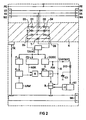
- FIG. 2 is a block diagram of in FIG. 1 shown only schematically illustrated protection device VPM.
- the protective device is connected between the inverter U and the motor M.
- the protective device measures the occurring motor terminal voltage at the terminals U4, V4 and W4 via the already described three-phase diode bridge with the diodes D1 to D6.
- the measurement voltage Umess formed by the rectification is fed to a filter F and controls at a predetermined voltage level via the trigger signal of a comparator K, which is acted upon by a reference voltage Uref, the subsequent electronics.
- the error discriminator FD serves a higher immunity to interference.
- the protection against too high clamping voltages between the motor M and drive control with the inverter U is done by igniting the three-phase diode bridge D1 to D6 downstream thyristor T and thereby caused short circuit of all motor connections via the three-phase diode bridge.
- the on-resistance of diode bridge D1 to D6 and thyristor T functions in this arrangement as a braking load.
- the firing pulse of the thyristor T sets a release relay R in a bistable state. This will override the drive control the already described signaling contact MK is interrupted until the termination of the braking of the engine by the already in connection with FIG. 1 described line loop of the signaling contact MK via the relay R is interrupted.
- the power supply Uversorg or P24 of the protection device with the corresponding components filter F, error discriminator ED, voltage comparator K and memory SP and the RESET trigger circuit RT is fed by means of a DC / DC converter from the voltage pulses output by the motor, which by the rectification by the three-phase diode bridge D1 to D6 in the form of the voltage Umeß ready.
- the protective device is self-sufficient and requires no additional auxiliary power.
- the diodes D1 to D6 of the three-phase diode bridge and the thyristor T are thermally connected to a heat sink K.
- a thermal contact TK which is connected to the heat sink K, protects the power components thyristor T and diode bridge D1 to D6 from overheating by switching off the motor via the signal contact MK and prevents them Way more brake cables.
- the thermal contact TK is looped in series with the release relay R in the line loop of the signaling contact MK.
- the design is such that upon connection of the protective device VPM a series circuit of drive control and inverter U, the protective device VPM itself and the motor M is mandatory. Line interruptions between motor M and protective device VPM lead to functional impairments and thus to fault detection. In a star point-shaped wiring from the motor M and the protection device VPM and drive control error detection would not be given in every case.
- the pulse width modulated signals of the inverter U reach the motor M via the protective device VPM.
- the measuring signal Umeß is formed by the phase rectifier bridge with the diodes D1 to D6.
- This measurement signal consists of rectangular pulses, which vary according to the required power requirement of the motor M in the pulse width.
- the square pulses are caused by the large reverse recovery time and the absence of a capacitor at the output of the phase rectifier bridge. This effect is utilized in the subsequent error discriminator FD for the detection of a faulty operation.
- the maximum pulse period Tmeß is considerably 3/2 of the pulse width modulation frequency f PWM .
- the error discriminator integrates this time and forms the signal ASK for calling the voltage comparator K. In the case of undisturbed operation, this signal blocks. A triggering of the thyristor T and a short circuit of the phase signals U, V, W is thereby prevented.
- the voltage comparator K measures the voltage pulse level via the filter F.
- the maximum amplitude is equal to the rectified one Voltage Umeß ⁇ 830 V ⁇ 1%, so an ignition of the thyristor T and thus a short circuit of the motor terminals through the AND operation of the AND gate & is blocked.
- the output of the AND operation thus remains inactive.
- the downstream circuit parts are therefore not activated and the signaling contact MK, driven via the release relay R, also remains closed.
- the DC / DC converter which is supplied via Umeß, forms the power supply of the protection device VPM.
- the resulting voltage P24 is for example + 24V.
- the faulty operation which will be explained in more detail below, becomes active by the occurrence of one of the incidents mentioned above (failure or still sitting the control of the drive, power failure, emergency stop, line interruption, etc.). The control of the drive has thus failed or stopped.
- the error discriminator FD calls the voltage comparator K.
- the subsequent memory and driver circuit SP ignites the thyristor T via the signal S and sets the release relay R.
- the phase signals U, V, W are short-circuited by the ignited thyristor T and the internal power supply is turned off.
- the signaling contact MK interrupts the signal "enable drive” and prevents a renewed connection of the machine.
- the reason for this is that a reset of the thyristor T is possible only after completion of the braking process.
- the thyristor T remains ignited up to the engine speed "zero". So that the RESET trigger circuit RT for resetting the release relay R can still be supplied with energy, is between the DC / DC converter and the RESET trigger electronics RT a diode D13 connected in the flow direction, the cathode is guided via a capacitor C1 to ground.
- the energy stored in the capacitor C1 is dissipated via the comparator of the RESET trigger.
- the trigger threshold of 13 V DC is reached after approx. 2.5 minutes, and the relay R is reset by the residual energy stored in the capacitor C1.
- the control of the drive is enabled again by the closed signaling contact 10 MK.
- the thermal contact TK measures the heat sink temperature of the heat sink K to protect against overloading and interrupts at a temperature of, for example,> 8 ° C, the signaling contact MK of the protection device VPM. A connection is made again at a temperature of for example ⁇ 60 ° C.
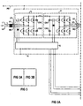
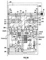
- FIGS. 3A and 3B is a schematic representation of a system with synchronous permanent-magnet motor M and a erfindungesammlungen redundant protective device against voltage feedback shown.
- the same elements are identified by the same reference numerals as in Figures 1 and 2.
- Inverter U and electronics E are already related to FIG. 1 described arrangement.
- the protective device itself is pronounced, which is carried out in two stages redundant. Each of the two stages is able to short the high motor terminal voltages, for which purpose a short-circuiting means in the form of a thyristor T1 and T2 is provided.
- a circuit complex comprising components ETZ1 or ETZ2, OK4 or OK5, F11 or F12 and relays R2 or R3 is installed redundantly.
- the two redundant stages of the protective device VPM are also redundant. Triggering one of the two stages requires the subsequent activation of the other stage. This is done by the mutual linking of the two voltage limiting electronics SBE1 and SBE2. Different thresholds Utr, which can occur due to component tolerances are compensated by this link or mutual information exchange.
- the voltage limiting electronics SBE1 sets the relay R with the contact K1.
- the signaling contact MK is interrupted for a predetermined time t R.
- the reset trigger RT closes the contact K1 again, as already on occasion of FIG. 2 was explained.
- the functionality and freedom from errors of the protective device VPM is guaranteed by the monitoring of the thyristor ignition by the respective circuit ETZ1 and ETZ2. If there is no coincidence, then the outputs of ETZ1 and ETZ2 have different voltage potential. This voltage passes through the filters FI1 and FI2 to the relays R2 and R3, which are set. The filters FI1 and FI2 suppress the running and switching times of the components. A reset does not take place in this case. Due to the permanent interruption of the signaling contact MK, the operation of the motor is no longer possible and a faulty protective device VPM must be replaced. The terminals P1 and P2 of the relays R2 and R3 serve to test this functionality.
- a monitoring of the thyristor ignition is also redundant.
- the control and the comparison of the signals is carried out by the two-channel control of the relays R2 and R3 with the contacts K2 and K3.
- Checking the function of the protective device VPM is done in the active and passive phases. In the active phase, the thyristor T1 or T2 ignites. Both relay connections therefore have the same potential (eg high).
- the passive phase in which the thyristors T1 and T2 are at rest, has the consequence that both relay terminals of R2 and R3 both lead opposite potential (eg low).
- the voltage difference is always zero at the relay inputs.
- the relay contacts K2 and K3 therefore remain closed. In case of a component failure, however, a channel remains at the same potential. He does not turn anymore. Due to the different potential at the relay terminals of the signaling contact MK is therefore interrupted in the manner described in the foregoing manner lasting.
- connection signals of the two stages are separated from the potential via optocouplers OK1 to OK5.
- a rollover of the dangerous motor terminal voltage in the event of a fault between circuits of the motor and the drive electronics is further limited.
- the two-stage redundant protective device VPM has the advantage that due to the redundancy, a component failure can be reliably detected.
- the two-stage does not increase the range of the tripping voltage, since both stages have the same threshold.
- the signaling contact MK is permanently interrupted and the replacement of the faulty device is absolutely necessary. Due to the additional voltage and fault monitoring function (as related to the FIG. 2 explained in more detail), the security is additionally increased.
- Even with a faulty relay R2 or R3 a failure in a power supply is reliably detected because in the short circuit, only one stage the corresponding associated thyristor T1 or T2 ignites, whereby the coincidence of the outputs of ETZ1 and ETZ2 is no longer given. This can cause high no-load terminal voltages of the motor M are short-circuited in the event of a fault and the necessary safety criteria are met.
- the protection device VPM measures in stages 1 and 2 the occurring motor terminal voltage Umeß in the respective voltage limiting electronics SBE1 and SBE2. Since the voltage level is ⁇ Utr, there is no ignition of the thyristors T1 and T2. The signaling contact MK remains closed. The relays R, R2 and R3 are not activated. The control electronics for the thyristor ignition ETZ1 and ETZ2 have coherent signals. The monitoring circuits ÜW1 and ÜW2 do not detect faulty states. The standby relay R4 is closed after drive and pulse enable of the motor M.
- Both stages of the protection device VPM have a voltage supply consisting of the measuring voltage Umeß with an amplitude of e.g. 500 V to 800 V generates a voltage of 24 V DC / DC converter.
- the output voltage level of the converter is monitored and, in the event of a fault, switches off the operational readiness via the ready-to-operate contact BK.
- Further error signals formed in the voltage limiting electronics SBE1 and SBE2 are linked in the monitoring circuit ÜW1 or ÜW2.
- a sum error signal ⁇ F is formed from ÜW1 and Optokoppier OK3 with ÜW2. An error detected in this way leads to the disconnection of the relay R4 with the contact K4 and thus to the interruption of movements of the motor M.
- the voltage limiting electronics SBE1 or SBE2 detects that the motor terminal voltage Umeß is greater than the tripping voltage Utr.
- the still passive voltage limiting electronics SBE is activated by the mutual exchange of information, for example by bridging a measuring resistor in the voltage divider of the trigger circuit. Thereafter, the two thyristors T1 and T2 are ignited via the corresponding unique signals S1 and S2.
- the process is repeatable.
- the heat generated by a short circuit is absorbed in the heat sink K.
- the thermal contact TK interrupts the alarm contact MK at high heat sink temperature and the machine is turned off. After a cooling time, the thermal contact closes contact K5 again. This ensures effective locking in the form of thermal protection for the power components.
- Another example of shutdown due to device failure may be that e.g. due to a component failure one of the two thyristor T1 or T2 does not fire or a channel of the coincidence electronics is defective. For this reason, there is no coincidence between the outputs of ETZ1 and ETZ2. Therefore, the release relay R2 or R3 is set with the respective contact K2 or K3. This requires a permanent interruption of the signaling contact MK, which can be forced only by replacing the protection device VPM.
- the fault monitoring described in the preceding examples guarantees the necessary operational reliability even in the event of component failure in the protection device VPM.
Landscapes
- Engineering & Computer Science (AREA)
- Power Engineering (AREA)
- Life Sciences & Earth Sciences (AREA)
- Sustainable Development (AREA)
- Sustainable Energy (AREA)
- Transportation (AREA)
- Mechanical Engineering (AREA)
- Control Of Ac Motors In General (AREA)
- Emergency Protection Circuit Devices (AREA)
- Stopping Of Electric Motors (AREA)
Claims (10)
- Dispositif ( VPM ) de protection à l'encontre d'une réaction de tension d'entraînements électriques à excitation permanente synchrone, qui est montée entre une électronique ( A ) d'entraînement et un moteur ( M ) sur les phases 25 ( U3, V3, W3 et U4, V4, W4 ) du moteur, le dispositif ( VPM ) de protection étant alimenté en énergie ( Uversorg1, Uversorg2) à partir de la tension ( U2, V2, W2 ) de phase redressée qui se produit,
caractérisé en ce que- il est prévu deux moyens ( SBE1, SBE2 ) redondants pour former respectivement un signal ( S1, S2 ) clair par redressement ( D1...D6, D4...D12 ) d'une surtension qui se produit, moyens qui sont montés en parallèle l'un avec l'autre et qui signalent la présence d'une réaction de tension néfaste, les deux moyens ( SBE1, SBE2 ) échangeant mutuellement des informations,- il est prévu deux moyens ( T1, T2 ) redondants pour court-circuiter la tension aux bornes du moteur, au moins l'un desdits moyens ( T1, T2 ) de court-circuit étant déclenché par le signal ( S1, S2 ) clair associé respectivement en présence d'une réaction de tension néfaste et, par ledit échange d'information mutuelle, l'autre moyen ( SBE1, SBE2 ) est activé pour former un signal ( S1, S2 ) clair, grâce à quoi l'autre moyen ( T1, T2 ) de court-circuit est déclenché, et- une résistance directe du moyen ( D1... D6..., D7... D12 ) de redressement et/ou du moyen ( T1, T2 ) de court-circuit agissant comme charge de frein. - Dispositif de protection selon la revendication 1, caractérisé en ce qu'en présence d'une réaction de tension néfaste, chaque moyen ( T1, T2 ) de court-circuit reste activé jusqu'à ce que l'on atteigne une vitesse de rotation nulle du moteur.
- Dispositif de protection selon l'une des revendications 1 ou 2, caractérisé en ce que chaque moyen de redressement est constitué sous la forme d'un pont ( D1... D6, D7.... D12 ) de diodes en courant triphasé par les phases ( U3, V3, W3 et U4, V4, W4 ) du moteur et chaque moyen de court-circuit est conformé en thyristor ( T1, T2 ), chaque thyristor ( T1, T2 ) court-circuitant toutes les bornes du moteur par le pont ( D1... D6, D7... D12 ) de diodes en courant triphasé respectif.
- Dispositif de protection selon l'une des revendications 1 à 3, caractérisé en ce que, pour détecter les défaillances de composants lors de l'activation de seulement un moyen ( T1, T2 ) de court-circuit en raison d'une réaction de tenison néfaste, on actionne supplémentairement un moyen ( K2, K3 ) par lequel la régulation de l'entraînement est interrompue.
- Dispositif de protection suivant la revendication 4, caractérisé en ce que la régulation de l'entraînement est interrompue jusqu'à ce que l'opération de freinage soit achevée.
- Dispositif de protection suivant l'une des revendications 3 à 5, caractérisé en ce que pour protéger chaque pont ( D1... D6, D7.... D12 ) de diodes en courant triphasé et chaque thyristor ( T1, T2 ) d'une surchauffe, il est prévu un thermocontact ( TK ) par lequel la régulation de l'entraînement peut être interrompue.
- Dispositif de protection suivant l'une des revendications 1 à 6, caractérisé en ce que, par un couplage électrique fixe entre des condensateurs ( CK1, CK2 ) de circuit intermédiaire de la régulation ( A ) d'entraînement et les phases ( U3, V3, W3 et U4, V4, W4 ) du moteur, une surtension se produisant en cas de panne du dispositif ( VPM ) de protection peut être limitée temporairement la tension de formatation des condensateurs.
- Dispositif de protection suivant l'une des revendications 1 à 7, caractérisé en ce que les deux moyens ( SBE1, SBE2 ) redondants, pour la formation de respectivement un signal ( S1, S2 ) clair, échangent mutuellement de l'information par une section ( OK1, OK2 ) directionnelle et séparée galvaniquement.
- Dispositif de protection suivant l'une des revendications 1 à 8, caractérisé en ce qu'il est prévu un moyen ( ÜW1, ÜW2, &, K4 ) supplémentaire de contrôle qui, lorsque les tensions ( Uversorg1, Uversorg2 ) d'alimentation, qui sont obtenues respectivement à partir de la tension ( U2, V2, W2 ) de phase redressée par les deux moyens ( D1...D6, D7...D12 ) de redressement, présentent un écart, est activé et interrompt la régulation de l'entraînement.
- Dispositif de protection suivant l'une des revendications 1 à 9, caractérisé en ce que, par un signal ( S ) clair en présence d'une réaction de tensions néfaste, un moyen ( MK ) supplémentaire est actionné, moyen par lequel la régulation d'entraînement est interrompue.
Applications Claiming Priority (2)
| Application Number | Priority Date | Filing Date | Title |
|---|---|---|---|
| DE29813080U DE29813080U1 (de) | 1998-07-22 | 1998-07-22 | Schutzeinrichtung gegen Spannungsrückwirkung permanenterregter elektrischer Antriebe |
| DE29813080U | 1998-07-22 |
Publications (3)
| Publication Number | Publication Date |
|---|---|
| EP0974483A2 EP0974483A2 (fr) | 2000-01-26 |
| EP0974483A3 EP0974483A3 (fr) | 2001-10-17 |
| EP0974483B1 true EP0974483B1 (fr) | 2009-02-25 |
Family
ID=8060241
Family Applications (1)
| Application Number | Title | Priority Date | Filing Date |
|---|---|---|---|
| EP99113348A Expired - Lifetime EP0974483B1 (fr) | 1998-07-22 | 1999-07-09 | Dispostif de protection contre tensions rétroactives d'entraînement électrique à excitation permanente |
Country Status (2)
| Country | Link |
|---|---|
| EP (1) | EP0974483B1 (fr) |
| DE (2) | DE29813080U1 (fr) |
Families Citing this family (14)
| Publication number | Priority date | Publication date | Assignee | Title |
|---|---|---|---|---|
| DE102005009341A1 (de) | 2004-11-04 | 2006-05-18 | Diehl Ako Stiftung & Co. Kg | Schaltungsananordnung und Verfahren zur Steuerung eines Elektromotors, insbesondere einer Waschmaschine |
| DE102005046961A1 (de) * | 2005-09-30 | 2007-04-12 | Siemens Ag | Ansteuersystem und Verfahren zur Ansteuerung für einen permanent erregten Elektromotor |
| WO2008122602A1 (fr) * | 2007-04-05 | 2008-10-16 | Siemens Aktiengesellschaft | Protection contre la surtension pour un convertisseur |
| DE102007059492B4 (de) * | 2007-12-11 | 2018-06-28 | Kuka Deutschland Gmbh | Industrieroboter |
| DE102009046616A1 (de) | 2009-11-11 | 2011-05-19 | Zf Friedrichshafen Ag | Wechselrichter |
| DE102009046615A1 (de) | 2009-11-11 | 2011-05-19 | Zf Friedrichshafen Ag | Leistungsschalteranordnung für einen Wechselrichter |
| DE102009046617A1 (de) | 2009-11-11 | 2011-05-19 | Zf Friedrichshafen Ag | Wechselrichter |
| EP2372860A1 (fr) * | 2010-03-30 | 2011-10-05 | Converteam Technology Ltd | Circuits de protection et procédés pour machines électriques |
| EP2573929B1 (fr) | 2011-07-11 | 2019-07-10 | MAGNA Powertrain GmbH & Co KG | Commande de fonctionnement d'un convertisseur pour une machine électrique |
| ES2779200T3 (es) | 2012-05-31 | 2020-08-14 | Ziehl-Abegg Se | Convertidor de frecuencia, método para frenar un motor síncrono y unidad motriz |
| WO2017101996A1 (fr) | 2015-12-16 | 2017-06-22 | L-3 Communications Magnet-Motor Gmbh | Unité électronique de puissance |
| WO2019034287A1 (fr) * | 2017-08-16 | 2019-02-21 | Sew-Eurodrive Gmbh & Co. Kg | Entraînement présentant un moteur synchrone et un convertisseur |
| DE102020206478A1 (de) | 2020-05-25 | 2021-11-25 | Robert Bosch Gesellschaft mit beschränkter Haftung | Steuervorrichtung für einen Stromrichter, elektrisches Antriebssystem und Verfahren zum Einstellen eines sicheren Betriebszustandes |
| CN119861067B (zh) * | 2025-03-25 | 2025-07-29 | 钢研纳克检测技术股份有限公司 | 基于libs技术的再生高质量金属自动分类识别系统及方法 |
Citations (1)
| Publication number | Priority date | Publication date | Assignee | Title |
|---|---|---|---|---|
| EP0970840A2 (fr) * | 1998-07-08 | 2000-01-12 | Siemens Aktiengesellschaft | Dispositif de protection contre les rebonds de tension d'un entraínement électrique à excitation permanente |
Family Cites Families (3)
| Publication number | Priority date | Publication date | Assignee | Title |
|---|---|---|---|---|
| JPH0732627B2 (ja) * | 1987-02-19 | 1995-04-10 | 松下電器産業株式会社 | ブラシレスモ−タの保護装置 |
| JPH0650954B2 (ja) * | 1987-05-26 | 1994-06-29 | 株式会社東芝 | 無整流子電動機制御装置 |
| DE4306307C2 (de) * | 1993-03-01 | 1997-08-14 | Siemens Ag | Verfahren zur Schadensverhütung an numerisch gesteuerten Maschinen bei Netzausfall |
-
1998
- 1998-07-22 DE DE29813080U patent/DE29813080U1/de not_active Expired - Lifetime
-
1999
- 1999-07-09 DE DE59914966T patent/DE59914966D1/de not_active Expired - Lifetime
- 1999-07-09 EP EP99113348A patent/EP0974483B1/fr not_active Expired - Lifetime
Patent Citations (1)
| Publication number | Priority date | Publication date | Assignee | Title |
|---|---|---|---|---|
| EP0970840A2 (fr) * | 1998-07-08 | 2000-01-12 | Siemens Aktiengesellschaft | Dispositif de protection contre les rebonds de tension d'un entraínement électrique à excitation permanente |
Also Published As
| Publication number | Publication date |
|---|---|
| EP0974483A3 (fr) | 2001-10-17 |
| EP0974483A2 (fr) | 2000-01-26 |
| DE29813080U1 (de) | 1998-10-15 |
| DE59914966D1 (de) | 2009-04-09 |
Similar Documents
| Publication | Publication Date | Title |
|---|---|---|
| EP0974483A2 (fr) | Dispostif de protection contre tensions rétroactives d'entraínement électrique à excitation permanente | |
| DE102012101508A1 (de) | Verfahren und Vorrichtung zum Betreiben einer elektrischen Maschine | |
| DE102019005157A1 (de) | Motorantriebsvorrichtung mit Entladeschaltung für einen Kondensator eines Gleichstromanschlusses | |
| EP3378152B1 (fr) | Entraînement électrique pour un robot industriel | |
| DE102007058098B4 (de) | Sicheres Verfahren zum elektrischen Bremsen in einer Druckmaschine | |
| DE102007059492A1 (de) | Industrieroboter | |
| EP2608389A1 (fr) | Onduleur multiniveau avec une pluralité des sous-modules onduleur avec un dispositif de décharge central | |
| EP1004162B1 (fr) | Procede pour surveiller un appareil de protection | |
| DE102019215152A1 (de) | Motorantriebsvorrichtung | |
| DE102021133298A1 (de) | Ansteueranordnung und Verfahren zum Betreiben einer elektrischen Maschine | |
| DE102016104258A1 (de) | Leistungsumwandlungseinrichtung | |
| DE102022113800B4 (de) | Verfahren zum Betrieb einer elektrischen Maschine, insbesondere in einem Kraftfahrzeug, und Kraftfahrzeug | |
| EP1182762B1 (fr) | Outil électrique et procédé pour son utilisation | |
| DE102013225603B4 (de) | Stromrichtervorrichtung für eine Ein- oder Mehrachsanordnung und Betriebsverfahren | |
| EP3058652B1 (fr) | Appareil de commande à débranchement de sécurité | |
| EP0970840B1 (fr) | Dispositif de protection contre les rebonds de tension d'un entraînement électrique à excitation permanente | |
| CH701746A2 (de) | Generatorsystem mit direkt netzgekoppeltem Generator und Verfahren zum Durchfahren von Netzstörungen. | |
| EP1418664A2 (fr) | Moteur synchrone | |
| EP2672622A1 (fr) | Convertisseur de fréquence avec résistance au freinage et procédé de surveillance de la fonction de résistance au freinage d'un convertisseur de fréquence | |
| EP2774266B1 (fr) | Procédé et dispositif pour faire fonctionner une machine électrique à commutation électronique en cas de défaillance | |
| EP2608382A1 (fr) | Modulaire convertisseur de courant | |
| DE102022131772B4 (de) | Ansteueranordnung und Verfahren zum Betreiben einer elektrischen Maschine | |
| EP2096756B1 (fr) | Dispositif de séparation pour un semi-conducteur de puissance et son procédé de fonctionnement, module de puissance et installation du système | |
| EP1311047A2 (fr) | Méthode de surveillance orientée sûreté de la vitesse de rotation d'un moteur d'entraínement commandé | |
| EP0449807B1 (fr) | Procede de controle de courts-circuits pour onduleurs a circuit intermediaire |
Legal Events
| Date | Code | Title | Description |
|---|---|---|---|
| PUAI | Public reference made under article 153(3) epc to a published international application that has entered the european phase |
Free format text: ORIGINAL CODE: 0009012 |
|
| AK | Designated contracting states |
Kind code of ref document: A2 Designated state(s): AT BE CH CY DE DK ES FI FR GB GR IE IT LI LU MC NL PT SE Kind code of ref document: A2 Designated state(s): DE FR GB |
|
| AX | Request for extension of the european patent |
Free format text: AL;LT;LV;MK;RO;SI |
|
| PUAL | Search report despatched |
Free format text: ORIGINAL CODE: 0009013 |
|
| AK | Designated contracting states |
Kind code of ref document: A3 Designated state(s): AT BE CH CY DE DK ES FI FR GB GR IE IT LI LU MC NL PT SE |
|
| AX | Request for extension of the european patent |
Free format text: AL;LT;LV;MK;RO;SI |
|
| RIC1 | Information provided on ipc code assigned before grant |
Free format text: 7H 02H 7/12 A, 7H 02H 7/08 B, 7H 02P 6/00 B |
|
| 17P | Request for examination filed |
Effective date: 20011105 |
|
| AKX | Designation fees paid |
Free format text: DE DK FR |
|
| RBV | Designated contracting states (corrected) |
Designated state(s): DE FR GB |
|
| 17Q | First examination report despatched |
Effective date: 20071218 |
|
| GRAP | Despatch of communication of intention to grant a patent |
Free format text: ORIGINAL CODE: EPIDOSNIGR1 |
|
| GRAS | Grant fee paid |
Free format text: ORIGINAL CODE: EPIDOSNIGR3 |
|
| GRAA | (expected) grant |
Free format text: ORIGINAL CODE: 0009210 |
|
| AK | Designated contracting states |
Kind code of ref document: B1 Designated state(s): DE FR GB |
|
| REG | Reference to a national code |
Ref country code: GB Ref legal event code: FG4D Free format text: NOT ENGLISH |
|
| REF | Corresponds to: |
Ref document number: 59914966 Country of ref document: DE Date of ref document: 20090409 Kind code of ref document: P |
|
| PGFP | Annual fee paid to national office [announced via postgrant information from national office to epo] |
Ref country code: GB Payment date: 20090713 Year of fee payment: 11 |
|
| PLBE | No opposition filed within time limit |
Free format text: ORIGINAL CODE: 0009261 |
|
| STAA | Information on the status of an ep patent application or granted ep patent |
Free format text: STATUS: NO OPPOSITION FILED WITHIN TIME LIMIT |
|
| 26N | No opposition filed |
Effective date: 20091126 |
|
| GBPC | Gb: european patent ceased through non-payment of renewal fee |
Effective date: 20100709 |
|
| PG25 | Lapsed in a contracting state [announced via postgrant information from national office to epo] |
Ref country code: GB Free format text: LAPSE BECAUSE OF NON-PAYMENT OF DUE FEES Effective date: 20100709 |
|
| REG | Reference to a national code |
Ref country code: DE Ref legal event code: R084 Ref document number: 59914966 Country of ref document: DE Effective date: 20130613 |
|
| PGFP | Annual fee paid to national office [announced via postgrant information from national office to epo] |
Ref country code: DE Payment date: 20140919 Year of fee payment: 16 |
|
| REG | Reference to a national code |
Ref country code: FR Ref legal event code: PLFP Year of fee payment: 17 |
|
| PGFP | Annual fee paid to national office [announced via postgrant information from national office to epo] |
Ref country code: FR Payment date: 20150715 Year of fee payment: 17 |
|
| REG | Reference to a national code |
Ref country code: DE Ref legal event code: R119 Ref document number: 59914966 Country of ref document: DE |
|
| PG25 | Lapsed in a contracting state [announced via postgrant information from national office to epo] |
Ref country code: DE Free format text: LAPSE BECAUSE OF NON-PAYMENT OF DUE FEES Effective date: 20160202 |
|
| PG25 | Lapsed in a contracting state [announced via postgrant information from national office to epo] |
Ref country code: FR Free format text: LAPSE BECAUSE OF NON-PAYMENT OF DUE FEES Effective date: 20160801 |
|
| REG | Reference to a national code |
Ref country code: FR Ref legal event code: ST Effective date: 20170331 |