EP0974485B1 - Feu de signalisation pour véhicule - Google Patents
Feu de signalisation pour véhicule Download PDFInfo
- Publication number
- EP0974485B1 EP0974485B1 EP99113964A EP99113964A EP0974485B1 EP 0974485 B1 EP0974485 B1 EP 0974485B1 EP 99113964 A EP99113964 A EP 99113964A EP 99113964 A EP99113964 A EP 99113964A EP 0974485 B1 EP0974485 B1 EP 0974485B1
- Authority
- EP
- European Patent Office
- Prior art keywords
- led lamps
- reflecting surface
- light
- signal lamp
- reflecting
- Prior art date
- Legal status (The legal status is an assumption and is not a legal conclusion. Google has not performed a legal analysis and makes no representation as to the accuracy of the status listed.)
- Expired - Lifetime
Links
Images
Classifications
-
- B—PERFORMING OPERATIONS; TRANSPORTING
- B60—VEHICLES IN GENERAL
- B60Q—ARRANGEMENT OF SIGNALLING OR LIGHTING DEVICES, THE MOUNTING OR SUPPORTING THEREOF OR CIRCUITS THEREFOR, FOR VEHICLES IN GENERAL
- B60Q1/00—Arrangement of optical signalling or lighting devices, the mounting or supporting thereof or circuits therefor
- B60Q1/26—Arrangement of optical signalling or lighting devices, the mounting or supporting thereof or circuits therefor the devices being primarily intended to indicate the vehicle, or parts thereof, or to give signals, to other traffic
- B60Q1/2696—Mounting of devices using LEDs
-
- F—MECHANICAL ENGINEERING; LIGHTING; HEATING; WEAPONS; BLASTING
- F21—LIGHTING
- F21S—NON-PORTABLE LIGHTING DEVICES; SYSTEMS THEREOF; VEHICLE LIGHTING DEVICES SPECIALLY ADAPTED FOR VEHICLE EXTERIORS
- F21S43/00—Signalling devices specially adapted for vehicle exteriors, e.g. brake lamps, direction indicator lights or reversing lights
- F21S43/10—Signalling devices specially adapted for vehicle exteriors, e.g. brake lamps, direction indicator lights or reversing lights characterised by the light source
- F21S43/13—Signalling devices specially adapted for vehicle exteriors, e.g. brake lamps, direction indicator lights or reversing lights characterised by the light source characterised by the type of light source
- F21S43/14—Light emitting diodes [LED]
-
- F—MECHANICAL ENGINEERING; LIGHTING; HEATING; WEAPONS; BLASTING
- F21—LIGHTING
- F21S—NON-PORTABLE LIGHTING DEVICES; SYSTEMS THEREOF; VEHICLE LIGHTING DEVICES SPECIALLY ADAPTED FOR VEHICLE EXTERIORS
- F21S43/00—Signalling devices specially adapted for vehicle exteriors, e.g. brake lamps, direction indicator lights or reversing lights
- F21S43/30—Signalling devices specially adapted for vehicle exteriors, e.g. brake lamps, direction indicator lights or reversing lights characterised by reflectors
-
- F—MECHANICAL ENGINEERING; LIGHTING; HEATING; WEAPONS; BLASTING
- F21—LIGHTING
- F21V—FUNCTIONAL FEATURES OR DETAILS OF LIGHTING DEVICES OR SYSTEMS THEREOF; STRUCTURAL COMBINATIONS OF LIGHTING DEVICES WITH OTHER ARTICLES, NOT OTHERWISE PROVIDED FOR
- F21V7/00—Reflectors for light sources
- F21V7/0008—Reflectors for light sources providing for indirect lighting
-
- F—MECHANICAL ENGINEERING; LIGHTING; HEATING; WEAPONS; BLASTING
- F21—LIGHTING
- F21Y—INDEXING SCHEME ASSOCIATED WITH SUBCLASSES F21K, F21L, F21S and F21V, RELATING TO THE FORM OR THE KIND OF THE LIGHT SOURCES OR OF THE COLOUR OF THE LIGHT EMITTED
- F21Y2115/00—Light-generating elements of semiconductor light sources
- F21Y2115/10—Light-emitting diodes [LED]
Definitions
- the present invention relates to a signal lamp for a vehicle such as a tail lamp, a stop lamp, a turn signal lamp, or the like. More particularly, the present invention relates to a signal lamp for a vehicle using a plurality of light-emitting diode (hereinafter referred to as LED) lamps as a light source.
- LED light-emitting diode
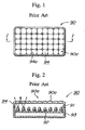
- FIGS. 1 and 2 illustrate a conventional signal lamp 90 for a vehicle using a plurality of LED lamps 91 as a light source.
- the plurality of LED lamps 91 are arranged in rows and columns to correspond to a light-emitting surface 90a of the signal lamp 90 for a vehicle.
- the plurality of LED lamps 91 are mounted on, e.g., a printed circuit board 92 and disposed in a housing 93.
- the LED lamps 91 has a beam-like light distribution property with a comparatively narrow illuminating angle.
- lens cuts 94a corresponding to the individual LED lamps 91 are imparted to the outer lens 94.
- the lens cuts 94a allow light beams from the LED lamps 91 to be diffused properly.
- the LED lamps 91 have narrow illuminating angles in the conventional signal lamp 90 for a vehicle thus constructed, light beams from the adjacent LED lamps 91 are not diffused sufficiently. Thus, when the light beams from the adjacent LED lamps 91 reach the outer lens 94, overlapping portions therebetween may be very little (see Figure 2). In other words, the outer lens 94 has portions on which the light beams are not incident. This satisfies the specifications of the signal lamp 90 in terms of the light distribution property but bright portions with the incident light and dark portions without the incident light are observed when the light-emitting surface 90a of the outer lens 94 are viewed directly by a viewer, resulting in a speckled pattern (see Figure 1). What results is the problem of a significantly impaired appearance of the lamp for a vehicle.
- the above mentioned problem can be solved by reducing the pitch of the LED lamps 91 disposed. In this case, however, the pitch reduced to 1/2 quadruples the number of LED lamps 91 to be mounted in the housing 93. This leads to some new problems of a temperature rise or a higher cost due to an increased number of LED lamps 91 to be mounted as well as an increased number of mounting steps during manufacturing.
- a signal lamp according to the pre-characterizing part of claim 1 is known from EP-A2-0 830 984.
- This prepublished patent document discloses a signal lamp for a vehicle comprising a plurality of light-emitting diode lamps as a light source, a reflecting surface corresponding to a light-emitting surface of that signal lamp, a housing for accommodating said LED lamps and the reflecting surface, said LED lamps being arranged along a periphery of the light-emitting surface such that an illuminating direction thereof is toward a center of said reflecting surface, said reflecting surface being partitioned into segments corresponding in number to said LED lamps.
- a signal lamp for a vehicle comprising a plurality of light-emitting diode lamps as a light source, a reflecting surface corresponding to a light-emitting surface of that signal lamp, a housing for accommodating said LED lamps and the reflecting surface, an outer lens disposed in opposing relation to the reflecting surface, said LED lamps being arranged along a periphery of the light-emitting surface such that an illuminating direction thereof is toward a center of said reflecting surface, said reflecting surface being partitioned into segments corresponding in number to said LED lamps.
- Another object of the present invention is to provide a signal lamp for a vehicle which performs light emission with uniform illuminance free from uneven illumination by using a smaller number of LED lamps than that used in a conventional signal lamp for a vehicle.
- the present invention provides a signal lamp for a vehicle, comprising: a plurality of LED lamps as a light source; a reflecting surface corresponding to a light-emitting surface of the signal lamp; a housing for accommodating the LED lamps and the reflecting surface; and an outer lens disposed in opposing relation to the reflecting surface, the LED lamps being arranged along a periphery of the light-emitting surface such that an illuminating direction thereof is toward a center of the reflecting surface, the reflecting surface being partitioned into segments corresponding in number to the LED lamps, the reflecting surface having a circular configuration, and the segments into which the reflecting surface is partitioned are arranged radially around the center of the reflecting surface.
- the LED lamps are arranged in an annular configuration along the periphery of the reflecting surface.
- the LED lamps are plural pairs of LED lamps, each pair of LED lamps being disposed in opposing relation to each other with a center axis of the reflecting surface interposed therebetween.
- the reflecting surface is composed of two types of reflecting portions being alternately arranged, one for reflecting a light beam from one of each pair of opposing LED lamps and the other for reflecting a light beam from the other of each pair of opposing LED lamps.
- a shade for blocking direct light beams from the LED lamps is provided adjacent the LED lamps.
- the signal lamp for a vehicle With the signal lamp for a vehicle according to the present invention, it becomes possible to illuminate the entire reflecting surface even with light beams from the LED lamps having comparatively narrow illuminating angles. This increases the illuminated area, allows the entire light-emitting surface to glow with uniform illuminance, and prevents uneven illumination.
- the reflecting surface With the reflecting surface thus construded, the area illuminated with light beams from the LED lamps is increased so that the light emitting surface is allowed to glow without uneven illumination by using a smaller number of LED lamps than in a conventional signal lamp for a vehicle with the light emitting surface having the same area.
- the reflecting surface is highly effective in reducing cost and the number of mounting steps for the signal lamp for a vehicle.
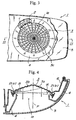
- a reference numeral 1 denotes a signal lamp for a vehicle according to the present invention.
- the signal lamp 1 for a vehicle is composed of: a plurality of LED lamps 2 as a light source; a reflecting surface 3; a shade 4; and an outer lens 5.
- the reflecting surface 3 is provided to roughly correspond to the light-emitting surface 1a to which the LED lamps are disposed to correspond in the conventional lamp.
- the LED lamps 2 are positioned to direct light to the reflecting surface 3. That is, light beams emitted from the plurality of LED lamps 2 are reflected by the reflecting surface 3 to travel in the illuminating direction of the lamp 1 in accordance with the present invention.
- the light distribution property required of the lamp 1 for a vehicle is formed at the time of reflection by the reflecting surface 3.
- the plurality of LED lamps 2 are disposed along the periphery of the reflecting surface 3 and have respective light-emitting center axes R directed toward the reflecting surface 3.
- the reflecting surface 3 has a circular configuration, while the plurality of LED lamps 2 are arranged in an annular configuration along the periphery of the reflecting surface 3.
- the shade 4 is provided adjacent the LED lamps 2 such that the LED lamps 2 are not directly viewed when a viewer looks in the signal lamp 1 for a vehicle from the outer lens side.
- the present invention has adopted LED lamps which are typical commercially available and each of which has an illuminating angle ⁇ of about 30° to 40°.
- the LED lamps 2 are located along the periphery of the reflecting surface 3 such that each diametrically opposing two of the LED lamps 2 are paired up with the center axis P of the reflecting surface 3 interposed therebetween.
- a reference numeral 6 denotes a housing. Although the housing 6 is formed integrally with the reflecting surface 3 in the present embodiment, it is not limited thereto.
- the reflecting surface 3 is configured such that it is present within the limits of the illuminating angle ⁇ of each of the LED lamps 2.
- a plurality of reflecting portions 3a and 3b are alternately arranged to compose the reflecting surface 3.
- Each of the reflecting portions 3a is for reflecting a light beam from the corresponding LED lamp 2 (a) which is one of each pair of LED lamps 2 disposed in opposing relation to each other with the center axis P interposed therebetween.
- each of the reflecting portions 3b is for reflecting a light beam from the corresponding LED lamp 2 (b) which is the other of each pair of LED lamps 2.
- the reflecting portions 3a are adapted to reflect substantially equal amounts of light in reflecting light beams from the LED lamps 2(a). Specifically, the reflecting portions 3a positioned closer to the LED lamps 2(a) have comparatively small areas, while the reflecting portions 3a positioned farther away from the LED lamps 2(a) have comparatively large areas. Likewise, the reflecting portions 3b for reflecting light beams from the LED lamps 2(b) are also adapted to reflect substantially equal amounts of light. In addition, the reflecting portions 3a adapted to reflect incident light from the LED lamps 2(a) and the reflecting portions 3b adapted to reflect incident light from the LED lamps 2(b) are paired up to form segments 3c each corresponding to one pair of LED lamps 2.
- the segments 3c correspond in number to the LED lamps 2 used in the signal lamp 1 for a vehicle.
- the segments 3c are arranged in a radial configuration around the center axis P.
- the light beams emitted from the LED lamps 2 are temporarily incident upon the reflecting surface 3 and then reflected thereby to travel in the illuminating direction. Since the segment 3c corresponding to one pair of LED lamps 2 is within the limits of the illuminating angle ⁇ of each of the LED lamps 2, the light beams emitted from the LED lamps 2 reach the entire surface of the segment 3c.
- the whole reflecting surface 3 is formed of the group of segments 3c, the light beams emitted from the LED lamps 2 reach the entire surface of the reflecting surface 3. Hence, uneven light illumination at the light-emitting surface 1a is prevented.
- a light-emitting area for each LED lamp 2 according to the present invention is increased compared with the light-emitting area in the conventional embodiment. Therefore, a smaller number of LED lamps 2 are sufficient for the light-emitting surface having the same area as in the conventional lamp.
Landscapes
- Engineering & Computer Science (AREA)
- General Engineering & Computer Science (AREA)
- Mechanical Engineering (AREA)
- Physics & Mathematics (AREA)
- Microelectronics & Electronic Packaging (AREA)
- Optics & Photonics (AREA)
- Non-Portable Lighting Devices Or Systems Thereof (AREA)
- Led Device Packages (AREA)
Claims (4)
- Lampe de signalisation pour véhicule comprenant :une pluralité de diodes électroluminescentes (DEL) (2) comme source de lumière ;une surface réfléchissante (3) correspondant à une surface d'émission de lumière de ladite lampe de signalisation (1) ;un logement pour recevoir lesdites DEL (2) et la surface réfléchissante (3) ; etune lentille externe (5) disposée en opposition par rapport à la surface réfléchissante (3) ;lesdites DEL (2) étant disposées le long d'une périphérie de la surface d'émission de lumière de telle manière qu'une direction d'éclairage de celle-ci soit vers un centre de ladite surface réfléchissante (3) ;ladite surface réfléchissante (3) étant partitionnée en segments (3c) correspondant en nombre auxdites DEL, caractérisée en ce que :ladite surface réfléchissante (3) a une configuration circulaire, les segments (3c) dans lesquels la surface réfléchissante (3) est partitionnée sont disposés de manière radiale autour du centre de la surface réfléchissante (3), et lesdites DEL (2) sont disposées suivant une configuration annulaire le long de la périphérie de ladite surface réfléchissante.
- Lampe de signalisation pour un véhicule selon la revendication 1, dans laquelle lesdites DEL (2) sont constituées de plusieurs paires de DEL, chaque paire de DEL (2) étant disposée en opposition l'une par rapport à l'autre, un axe central de la surface réfléchissante (3) étant interposé entre elles.
- Lampe de signalisation pour un véhicule selon la revendication 2, dans laquelle ladite surface réfléchissante (3) est composée de deux types de portions réfléchissantes (3a, 3b) étant disposées en alternance, l'une d'elles servant à réfléchir un faisceau de lumière de l'une des DEL de chaque paire de DEL située à l'opposé l'une de l'autre et l'autre servant à réfléchir un faisceau de lumière de l'autre DEL de chaque paire de DEL située à l'opposé l'une de l'autre.
- Lampe de signalisation pour un véhicule selon la revendication 1, dans laquelle un abat-jour (5) destiné à bloquer les faisceaux (2) de lumière directe provenant desdites DEL, est disposé de manière adjacente à celles-ci.
Applications Claiming Priority (2)
| Application Number | Priority Date | Filing Date | Title |
|---|---|---|---|
| JP20946098 | 1998-07-24 | ||
| JP10209460A JP2960928B1 (ja) | 1998-07-24 | 1998-07-24 | 車両用信号灯具 |
Publications (3)
| Publication Number | Publication Date |
|---|---|
| EP0974485A2 EP0974485A2 (fr) | 2000-01-26 |
| EP0974485A3 EP0974485A3 (fr) | 2001-04-25 |
| EP0974485B1 true EP0974485B1 (fr) | 2006-04-05 |
Family
ID=16573250
Family Applications (1)
| Application Number | Title | Priority Date | Filing Date |
|---|---|---|---|
| EP99113964A Expired - Lifetime EP0974485B1 (fr) | 1998-07-24 | 1999-07-17 | Feu de signalisation pour véhicule |
Country Status (4)
| Country | Link |
|---|---|
| US (1) | US6234646B1 (fr) |
| EP (1) | EP0974485B1 (fr) |
| JP (1) | JP2960928B1 (fr) |
| DE (1) | DE69930693T2 (fr) |
Cited By (2)
| Publication number | Priority date | Publication date | Assignee | Title |
|---|---|---|---|---|
| DE102007018698A1 (de) * | 2007-04-18 | 2008-10-23 | Bayerische Motoren Werke Aktiengesellschaft | Fahrzeug-Scheinwerfermodul |
| EP3447371B1 (fr) * | 2017-08-18 | 2022-11-16 | ZKW Group GmbH | Dispositif d'éclairage pour un phare de véhicule automobile |
Families Citing this family (65)
| Publication number | Priority date | Publication date | Assignee | Title |
|---|---|---|---|---|
| US6276821B1 (en) * | 1992-12-16 | 2001-08-21 | Donnelly Corporation | Vehicle exterior mirror system with signal light |
| US8066415B2 (en) | 1999-06-17 | 2011-11-29 | Magna Mirrors Of America, Inc. | Exterior mirror vision system for a vehicle |
| CZ297169B6 (cs) * | 1999-08-19 | 2006-09-13 | Autopal, S. R. O. | Signální svítilna s LED zdroji svetla |
| JP4182600B2 (ja) * | 1999-08-23 | 2008-11-19 | 市光工業株式会社 | Led光源を用いた車両用灯具 |
| JP4010084B2 (ja) | 1999-10-21 | 2007-11-21 | 市光工業株式会社 | 小型光源モジュール及び光源ユニット |
| JP2001283617A (ja) * | 2000-01-27 | 2001-10-12 | Koito Mfg Co Ltd | 車輌用灯具 |
| DE10019556A1 (de) * | 2000-04-20 | 2001-10-25 | Hella Kg Hueck & Co | Reflektor für eine Fahrzeugleuchte |
| DE10019559A1 (de) * | 2000-04-20 | 2001-10-25 | Hella Kg Hueck & Co | Fahrzeugleuchte |
| US8360615B2 (en) * | 2000-05-08 | 2013-01-29 | Farlight, Llc | LED light module for omnidirectional luminaire |
| DE10048561A1 (de) * | 2000-09-30 | 2002-04-11 | Hella Kg Hueck & Co | Lichteinheit für Fahrzeuge |
| JP3986779B2 (ja) * | 2001-08-15 | 2007-10-03 | 株式会社小糸製作所 | 車両用灯具 |
| KR100422789B1 (ko) * | 2001-08-23 | 2004-03-12 | 현대자동차주식회사 | 간접 조명방식의 차량용 램프 |
| JP2003100114A (ja) * | 2001-09-19 | 2003-04-04 | Koito Mfg Co Ltd | 車両用灯具 |
| DE10160052A1 (de) * | 2001-12-06 | 2003-06-18 | Hella Kg Hueck & Co | Fahrzeugleuchte |
| MXPA04008487A (es) * | 2002-03-02 | 2005-04-19 | Truck Lite Co | Lampara de vehiculo de diodo sencillo emisor de luz. |
| JP3998999B2 (ja) * | 2002-03-06 | 2007-10-31 | 株式会社小糸製作所 | 車両用灯具 |
| JP4360481B2 (ja) * | 2002-07-10 | 2009-11-11 | 株式会社小糸製作所 | 車両用灯具 |
| EP1411291B1 (fr) * | 2002-10-18 | 2011-04-20 | Ichikoh Industries, Ltd. | Feu de véhicule avec diodes électroluminescentes |
| US20050001433A1 (en) * | 2003-04-30 | 2005-01-06 | Seelink Technology Corporation | Display system having uniform luminosity and wind generator |
| FR2856135B1 (fr) * | 2003-06-16 | 2006-08-04 | Valeo Vision | Systeme d'eclairage ou de signalisation pour vehicule automobile. |
| DE10336974A1 (de) * | 2003-08-12 | 2005-03-10 | Hella Kgaa Hueck & Co | Signalleuchte für Fahrzeuge |
| US7387402B1 (en) | 2003-11-13 | 2008-06-17 | Lui Phillip Chun Wai | Multiple light LED flashlight |
| US7040782B2 (en) * | 2004-02-19 | 2006-05-09 | Gelcore, Llc | Off-axis parabolic reflector |
| DE102004011600B4 (de) * | 2004-03-10 | 2011-07-28 | odelo GmbH, 71409 | Heckleuchte eines Fahrzeugs |
| USD500153S1 (en) | 2004-04-01 | 2004-12-21 | Grote Industries, Inc. | Vehicle indicator |
| US7245203B2 (en) * | 2004-04-01 | 2007-07-17 | Grote Industries, Inc. | Indicator apparatus and method for a vehicle using side-emitting light-emitting diode |
| US20050225452A1 (en) * | 2004-04-01 | 2005-10-13 | Stephens Newel L | Indicator apparatus and method for a vehicle using side-emitting light-emitting diode |
| DE102004020154B4 (de) * | 2004-04-24 | 2012-12-13 | Hella Kgaa Hueck & Co. | Leuchte für Fahrzeuge |
| US20060013004A1 (en) * | 2004-07-16 | 2006-01-19 | Charles Coushaine | LED sideward emitting lamp |
| JP2006164858A (ja) * | 2004-12-09 | 2006-06-22 | Koito Mfg Co Ltd | 車両用照明灯具 |
| US8993055B2 (en) | 2005-10-27 | 2015-03-31 | Asm International N.V. | Enhanced thin film deposition |
| US20080074891A1 (en) * | 2006-09-27 | 2008-03-27 | Chih-Cheng Chuang | Light |
| US8268409B2 (en) * | 2006-10-25 | 2012-09-18 | Asm America, Inc. | Plasma-enhanced deposition of metal carbide films |
| US7611751B2 (en) | 2006-11-01 | 2009-11-03 | Asm America, Inc. | Vapor deposition of metal carbide films |
| JP4850678B2 (ja) * | 2006-12-11 | 2012-01-11 | 株式会社小糸製作所 | 車両用標識灯 |
| US7713874B2 (en) * | 2007-05-02 | 2010-05-11 | Asm America, Inc. | Periodic plasma annealing in an ALD-type process |
| WO2009129332A2 (fr) * | 2008-04-16 | 2009-10-22 | Asm America, Inc. | Dépôt par couche atomique de films de carbure métallique à l'aide de composés hydrocarbure d'aluminium |
| US7666474B2 (en) | 2008-05-07 | 2010-02-23 | Asm America, Inc. | Plasma-enhanced pulsed deposition of metal carbide films |
| US20100039824A1 (en) * | 2008-08-15 | 2010-02-18 | Maxzone Vehicle Lighting Corp. | Lighting device capable of projecting an output with a ring band portion |
| JP5264448B2 (ja) * | 2008-12-02 | 2013-08-14 | 株式会社小糸製作所 | 投射型の車両用灯具 |
| JP5212720B2 (ja) * | 2008-12-11 | 2013-06-19 | スタンレー電気株式会社 | 灯具 |
| US7963683B2 (en) * | 2008-12-22 | 2011-06-21 | Federal Signal Corporation | Rotating light |
| MX2011005143A (es) * | 2010-05-14 | 2011-11-14 | Grote Industries Inc | Montaje para una fuente de iluminacion. |
| JP5989305B2 (ja) * | 2011-01-14 | 2016-09-07 | エルジー イノテック カンパニー リミテッド | バックライトユニット及びそれを用いたディスプレイ装置 |
| KR101943447B1 (ko) * | 2012-02-23 | 2019-01-29 | 엘지이노텍 주식회사 | 조명 유닛 및 그를 이용한 디스플레이 장치 |
| US9412602B2 (en) | 2013-03-13 | 2016-08-09 | Asm Ip Holding B.V. | Deposition of smooth metal nitride films |
| US8846550B1 (en) | 2013-03-14 | 2014-09-30 | Asm Ip Holding B.V. | Silane or borane treatment of metal thin films |
| US8841182B1 (en) | 2013-03-14 | 2014-09-23 | Asm Ip Holding B.V. | Silane and borane treatments for titanium carbide films |
| US9394609B2 (en) | 2014-02-13 | 2016-07-19 | Asm Ip Holding B.V. | Atomic layer deposition of aluminum fluoride thin films |
| US10643925B2 (en) | 2014-04-17 | 2020-05-05 | Asm Ip Holding B.V. | Fluorine-containing conductive films |
| US10002936B2 (en) | 2014-10-23 | 2018-06-19 | Asm Ip Holding B.V. | Titanium aluminum and tantalum aluminum thin films |
| US10293742B2 (en) * | 2014-10-27 | 2019-05-21 | SMR Patents S.à.r.l. | Lamp assembly for a vehicle |
| US9941425B2 (en) | 2015-10-16 | 2018-04-10 | Asm Ip Holdings B.V. | Photoactive devices and materials |
| US9786491B2 (en) | 2015-11-12 | 2017-10-10 | Asm Ip Holding B.V. | Formation of SiOCN thin films |
| US9786492B2 (en) | 2015-11-12 | 2017-10-10 | Asm Ip Holding B.V. | Formation of SiOCN thin films |
| KR102378021B1 (ko) | 2016-05-06 | 2022-03-23 | 에이에스엠 아이피 홀딩 비.브이. | SiOC 박막의 형성 |
| US11543097B2 (en) * | 2016-06-13 | 2023-01-03 | Flex-N-Gate Advanced Product Development, Llc | Lit image projection devices and lamp assemblies containing the same for generation of three dimensional images |
| US10186420B2 (en) | 2016-11-29 | 2019-01-22 | Asm Ip Holding B.V. | Formation of silicon-containing thin films |
| US10847529B2 (en) | 2017-04-13 | 2020-11-24 | Asm Ip Holding B.V. | Substrate processing method and device manufactured by the same |
| US10504901B2 (en) | 2017-04-26 | 2019-12-10 | Asm Ip Holding B.V. | Substrate processing method and device manufactured using the same |
| CN110546302B (zh) | 2017-05-05 | 2022-05-27 | Asm Ip 控股有限公司 | 用于受控形成含氧薄膜的等离子体增强沉积方法 |
| US10991573B2 (en) | 2017-12-04 | 2021-04-27 | Asm Ip Holding B.V. | Uniform deposition of SiOC on dielectric and metal surfaces |
| US12359315B2 (en) | 2019-02-14 | 2025-07-15 | Asm Ip Holding B.V. | Deposition of oxides and nitrides |
| US12142479B2 (en) | 2020-01-17 | 2024-11-12 | Asm Ip Holding B.V. | Formation of SiOCN thin films |
| US12341005B2 (en) | 2020-01-17 | 2025-06-24 | Asm Ip Holding B.V. | Formation of SiCN thin films |
Family Cites Families (9)
| Publication number | Priority date | Publication date | Assignee | Title |
|---|---|---|---|---|
| JPS57174803A (en) * | 1981-04-20 | 1982-10-27 | Masayasu Negishi | Surface light source device |
| DE3480294D1 (en) * | 1984-11-15 | 1989-11-30 | Japan Traffic Manage Tech Ass | Signal light unit having heat dissipating function |
| US4929866A (en) * | 1987-11-17 | 1990-05-29 | Mitsubishi Cable Industries, Ltd. | Light emitting diode lamp |
| DE3929955A1 (de) * | 1989-09-08 | 1991-03-14 | Inotec Gmbh Ges Fuer Innovativ | Lichtstrahler |
| US5152601A (en) * | 1992-02-18 | 1992-10-06 | Ferng Shing Lai | Solar power-operated construction work warning lamp |
| IT1281366B1 (it) * | 1995-09-27 | 1998-02-18 | Carello Spa | Dispositivo di illuminazione realizzabile con spessore ridotto, in particolare proiettore o fanale per veicoli |
| DE19638081A1 (de) * | 1996-09-19 | 1998-03-26 | Hella Kg Hueck & Co | Leuchte für Fahrzeuge |
| CN1105852C (zh) * | 1996-10-16 | 2003-04-16 | 皇家菲利浦电子有限公司 | 具有发光二极管的信号灯 |
| US5838247A (en) * | 1997-04-01 | 1998-11-17 | Bladowski; Witold S. | Solid state light system |
-
1998
- 1998-07-24 JP JP10209460A patent/JP2960928B1/ja not_active Expired - Lifetime
-
1999
- 1999-07-17 EP EP99113964A patent/EP0974485B1/fr not_active Expired - Lifetime
- 1999-07-17 DE DE69930693T patent/DE69930693T2/de not_active Expired - Lifetime
- 1999-07-21 US US09/358,452 patent/US6234646B1/en not_active Expired - Lifetime
Cited By (2)
| Publication number | Priority date | Publication date | Assignee | Title |
|---|---|---|---|---|
| DE102007018698A1 (de) * | 2007-04-18 | 2008-10-23 | Bayerische Motoren Werke Aktiengesellschaft | Fahrzeug-Scheinwerfermodul |
| EP3447371B1 (fr) * | 2017-08-18 | 2022-11-16 | ZKW Group GmbH | Dispositif d'éclairage pour un phare de véhicule automobile |
Also Published As
| Publication number | Publication date |
|---|---|
| JP2960928B1 (ja) | 1999-10-12 |
| DE69930693D1 (de) | 2006-05-18 |
| DE69930693T2 (de) | 2007-01-11 |
| US6234646B1 (en) | 2001-05-22 |
| EP0974485A3 (fr) | 2001-04-25 |
| JP2000040410A (ja) | 2000-02-08 |
| EP0974485A2 (fr) | 2000-01-26 |
Similar Documents
| Publication | Publication Date | Title |
|---|---|---|
| EP0974485B1 (fr) | Feu de signalisation pour véhicule | |
| US4680678A (en) | Lighting fixture for vehicle | |
| US6619825B2 (en) | Vehicle lamp | |
| US6929390B2 (en) | Vehicular lamp | |
| US6332701B1 (en) | Vehicle lamp | |
| EP1126209B1 (fr) | Feu double empilé pour véhicule | |
| US20020034081A1 (en) | Vehicle lamp | |
| EP1698824B1 (fr) | Guide optique, assemblage avec guide optique, lampe comprenant ce dispositif | |
| US20020053878A1 (en) | Antenna and electronic device containing the same | |
| EP1598593B1 (fr) | Phare de véhicule | |
| US20130063961A1 (en) | Vehicle lamp | |
| EP0922903B1 (fr) | Feu multifonction arrière pour véhicule | |
| JPH06349306A (ja) | Led光源の灯具 | |
| US6267490B1 (en) | Vehicular lamp | |
| JP2000251508A5 (ja) | 灯具 | |
| US7416324B1 (en) | Multi-color or multi-function LED vehicle light assembly | |
| EP4445070B1 (fr) | Élément de guidage de lumière, dispositif d'éclairage et véhicule | |
| JP3593065B2 (ja) | 遊技機の照明構造 | |
| WO2001002771A1 (fr) | Eclairage et feux de signalisation | |
| EP0886101A2 (fr) | Lampe pour véhicules automobiles | |
| CN218626603U (zh) | Led透镜、发光装置及显示设备 | |
| JPS62108584A (ja) | 発光ダイオ−ド灯具 | |
| JP3975303B2 (ja) | 発光ダイオードユニット及びその点灯方式 | |
| JP4366857B2 (ja) | メータ部照明装置 | |
| JP2001076513A (ja) | 車両用灯具 |
Legal Events
| Date | Code | Title | Description |
|---|---|---|---|
| PUAI | Public reference made under article 153(3) epc to a published international application that has entered the european phase |
Free format text: ORIGINAL CODE: 0009012 |
|
| AK | Designated contracting states |
Kind code of ref document: A2 Designated state(s): DE FR GB |
|
| AX | Request for extension of the european patent |
Free format text: AL;LT;LV;MK;RO;SI |
|
| PUAL | Search report despatched |
Free format text: ORIGINAL CODE: 0009013 |
|
| AK | Designated contracting states |
Kind code of ref document: A3 Designated state(s): AT BE CH CY DE DK ES FI FR GB GR IE IT LI LU MC NL PT SE |
|
| AX | Request for extension of the european patent |
Free format text: AL;LT;LV;MK;RO;SI |
|
| RIC1 | Information provided on ipc code assigned before grant |
Free format text: 7B 60Q 1/26 A, 7F 21Q 1/00 B, 7F 21W 111:00 Z |
|
| 17P | Request for examination filed |
Effective date: 20010525 |
|
| AKX | Designation fees paid |
Free format text: DE FR GB |
|
| 17Q | First examination report despatched |
Effective date: 20040212 |
|
| GRAP | Despatch of communication of intention to grant a patent |
Free format text: ORIGINAL CODE: EPIDOSNIGR1 |
|
| GRAS | Grant fee paid |
Free format text: ORIGINAL CODE: EPIDOSNIGR3 |
|
| GRAA | (expected) grant |
Free format text: ORIGINAL CODE: 0009210 |
|
| AK | Designated contracting states |
Kind code of ref document: B1 Designated state(s): DE FR GB |
|
| REG | Reference to a national code |
Ref country code: GB Ref legal event code: FG4D |
|
| RIC1 | Information provided on ipc code assigned before grant |
Ipc: F21W 111/00 20060101ALI20060210BHEP Ipc: F21S 19/00 20060101ALI20060210BHEP Ipc: F21S 13/00 20060101ALI20060210BHEP Ipc: F21S 8/10 20060101ALI20060210BHEP Ipc: B60Q 1/26 20060101AFI20060210BHEP |
|
| REF | Corresponds to: |
Ref document number: 69930693 Country of ref document: DE Date of ref document: 20060518 Kind code of ref document: P |
|
| ET | Fr: translation filed | ||
| PLBE | No opposition filed within time limit |
Free format text: ORIGINAL CODE: 0009261 |
|
| STAA | Information on the status of an ep patent application or granted ep patent |
Free format text: STATUS: NO OPPOSITION FILED WITHIN TIME LIMIT |
|
| 26N | No opposition filed |
Effective date: 20070108 |
|
| REG | Reference to a national code |
Ref country code: FR Ref legal event code: PLFP Year of fee payment: 18 |
|
| PGFP | Annual fee paid to national office [announced via postgrant information from national office to epo] |
Ref country code: FR Payment date: 20160613 Year of fee payment: 18 |
|
| PGFP | Annual fee paid to national office [announced via postgrant information from national office to epo] |
Ref country code: DE Payment date: 20160712 Year of fee payment: 18 Ref country code: GB Payment date: 20160713 Year of fee payment: 18 |
|
| REG | Reference to a national code |
Ref country code: DE Ref legal event code: R119 Ref document number: 69930693 Country of ref document: DE |
|
| GBPC | Gb: european patent ceased through non-payment of renewal fee |
Effective date: 20170717 |
|
| REG | Reference to a national code |
Ref country code: FR Ref legal event code: ST Effective date: 20180330 |
|
| PG25 | Lapsed in a contracting state [announced via postgrant information from national office to epo] |
Ref country code: GB Free format text: LAPSE BECAUSE OF NON-PAYMENT OF DUE FEES Effective date: 20170717 Ref country code: DE Free format text: LAPSE BECAUSE OF NON-PAYMENT OF DUE FEES Effective date: 20180201 |
|
| PG25 | Lapsed in a contracting state [announced via postgrant information from national office to epo] |
Ref country code: FR Free format text: LAPSE BECAUSE OF NON-PAYMENT OF DUE FEES Effective date: 20170731 |