EP0974506A2 - Dispositif d'actionnement de frein - Google Patents
Dispositif d'actionnement de frein Download PDFInfo
- Publication number
- EP0974506A2 EP0974506A2 EP99111387A EP99111387A EP0974506A2 EP 0974506 A2 EP0974506 A2 EP 0974506A2 EP 99111387 A EP99111387 A EP 99111387A EP 99111387 A EP99111387 A EP 99111387A EP 0974506 A2 EP0974506 A2 EP 0974506A2
- Authority
- EP
- European Patent Office
- Prior art keywords
- coupling member
- locking
- movement
- housing
- locking device
- Prior art date
- Legal status (The legal status is an assumption and is not a legal conclusion. Google has not performed a legal analysis and makes no representation as to the accuracy of the status listed.)
- Granted
Links
- 230000008878 coupling Effects 0.000 claims abstract description 57
- 238000010168 coupling process Methods 0.000 claims abstract description 57
- 238000005859 coupling reaction Methods 0.000 claims abstract description 57
- 230000000903 blocking effect Effects 0.000 claims abstract description 17
- 230000007246 mechanism Effects 0.000 claims abstract description 14
- 238000003860 storage Methods 0.000 claims abstract description 4
- 230000033001 locomotion Effects 0.000 claims description 40
- 230000005540 biological transmission Effects 0.000 claims description 11
- 238000006243 chemical reaction Methods 0.000 claims description 6
- 230000036961 partial effect Effects 0.000 claims description 5
- 238000012546 transfer Methods 0.000 claims description 4
- 238000004146 energy storage Methods 0.000 abstract description 2
- 230000006835 compression Effects 0.000 description 12
- 238000007906 compression Methods 0.000 description 12
- 238000000034 method Methods 0.000 description 7
- 230000008569 process Effects 0.000 description 7
- 230000000670 limiting effect Effects 0.000 description 4
- 230000007547 defect Effects 0.000 description 3
- 239000012528 membrane Substances 0.000 description 3
- 230000009467 reduction Effects 0.000 description 3
- 230000008901 benefit Effects 0.000 description 2
- 238000010276 construction Methods 0.000 description 2
- 238000013461 design Methods 0.000 description 2
- 230000000694 effects Effects 0.000 description 2
- 230000006870 function Effects 0.000 description 2
- 238000009434 installation Methods 0.000 description 2
- 238000004519 manufacturing process Methods 0.000 description 2
- 230000008439 repair process Effects 0.000 description 2
- 230000001960 triggered effect Effects 0.000 description 2
- 230000004888 barrier function Effects 0.000 description 1
- 230000002950 deficient Effects 0.000 description 1
- 238000001514 detection method Methods 0.000 description 1
- 230000005611 electricity Effects 0.000 description 1
- 238000005516 engineering process Methods 0.000 description 1
- 230000005284 excitation Effects 0.000 description 1
- 230000002349 favourable effect Effects 0.000 description 1
- 230000002401 inhibitory effect Effects 0.000 description 1
- 230000003993 interaction Effects 0.000 description 1
- 230000005923 long-lasting effect Effects 0.000 description 1
- 238000012423 maintenance Methods 0.000 description 1
- 210000003205 muscle Anatomy 0.000 description 1
- 230000002040 relaxant effect Effects 0.000 description 1
- 230000002441 reversible effect Effects 0.000 description 1
- 238000005096 rolling process Methods 0.000 description 1
- 238000005476 soldering Methods 0.000 description 1
- 238000012360 testing method Methods 0.000 description 1
- 238000012549 training Methods 0.000 description 1
- 238000003466 welding Methods 0.000 description 1
Images


Classifications
-
- F—MECHANICAL ENGINEERING; LIGHTING; HEATING; WEAPONS; BLASTING
- F16—ENGINEERING ELEMENTS AND UNITS; GENERAL MEASURES FOR PRODUCING AND MAINTAINING EFFECTIVE FUNCTIONING OF MACHINES OR INSTALLATIONS; THERMAL INSULATION IN GENERAL
- F16D—COUPLINGS FOR TRANSMITTING ROTATION; CLUTCHES; BRAKES
- F16D65/00—Parts or details
- F16D65/14—Actuating mechanisms for brakes; Means for initiating operation at a predetermined position
- F16D65/28—Actuating mechanisms for brakes; Means for initiating operation at a predetermined position arranged apart from the brake
-
- B—PERFORMING OPERATIONS; TRANSPORTING
- B60—VEHICLES IN GENERAL
- B60T—VEHICLE BRAKE CONTROL SYSTEMS OR PARTS THEREOF; BRAKE CONTROL SYSTEMS OR PARTS THEREOF, IN GENERAL; ARRANGEMENT OF BRAKING ELEMENTS ON VEHICLES IN GENERAL; PORTABLE DEVICES FOR PREVENTING UNWANTED MOVEMENT OF VEHICLES; VEHICLE MODIFICATIONS TO FACILITATE COOLING OF BRAKES
- B60T13/00—Transmitting braking action from initiating means to ultimate brake actuator with power assistance or drive; Brake systems incorporating such transmitting means, e.g. air-pressure brake systems
- B60T13/74—Transmitting braking action from initiating means to ultimate brake actuator with power assistance or drive; Brake systems incorporating such transmitting means, e.g. air-pressure brake systems with electrical assistance or drive
- B60T13/741—Transmitting braking action from initiating means to ultimate brake actuator with power assistance or drive; Brake systems incorporating such transmitting means, e.g. air-pressure brake systems with electrical assistance or drive acting on an ultimate actuator
- B60T13/743—Transmitting braking action from initiating means to ultimate brake actuator with power assistance or drive; Brake systems incorporating such transmitting means, e.g. air-pressure brake systems with electrical assistance or drive acting on an ultimate actuator with a spring accumulator
-
- B—PERFORMING OPERATIONS; TRANSPORTING
- B60—VEHICLES IN GENERAL
- B60T—VEHICLE BRAKE CONTROL SYSTEMS OR PARTS THEREOF; BRAKE CONTROL SYSTEMS OR PARTS THEREOF, IN GENERAL; ARRANGEMENT OF BRAKING ELEMENTS ON VEHICLES IN GENERAL; PORTABLE DEVICES FOR PREVENTING UNWANTED MOVEMENT OF VEHICLES; VEHICLE MODIFICATIONS TO FACILITATE COOLING OF BRAKES
- B60T7/00—Brake-action initiating means
- B60T7/02—Brake-action initiating means for personal initiation
- B60T7/08—Brake-action initiating means for personal initiation hand actuated
- B60T7/10—Disposition of hand control
- B60T7/107—Disposition of hand control with electrical power assistance
-
- F—MECHANICAL ENGINEERING; LIGHTING; HEATING; WEAPONS; BLASTING
- F16—ENGINEERING ELEMENTS AND UNITS; GENERAL MEASURES FOR PRODUCING AND MAINTAINING EFFECTIVE FUNCTIONING OF MACHINES OR INSTALLATIONS; THERMAL INSULATION IN GENERAL
- F16D—COUPLINGS FOR TRANSMITTING ROTATION; CLUTCHES; BRAKES
- F16D2121/00—Type of actuator operation force
- F16D2121/18—Electric or magnetic
- F16D2121/24—Electric or magnetic using motors
- F16D2121/26—Electric or magnetic using motors for releasing a normally applied brake
-
- F—MECHANICAL ENGINEERING; LIGHTING; HEATING; WEAPONS; BLASTING
- F16—ENGINEERING ELEMENTS AND UNITS; GENERAL MEASURES FOR PRODUCING AND MAINTAINING EFFECTIVE FUNCTIONING OF MACHINES OR INSTALLATIONS; THERMAL INSULATION IN GENERAL
- F16D—COUPLINGS FOR TRANSMITTING ROTATION; CLUTCHES; BRAKES
- F16D2125/00—Components of actuators
- F16D2125/18—Mechanical mechanisms
- F16D2125/20—Mechanical mechanisms converting rotation to linear movement or vice versa
- F16D2125/34—Mechanical mechanisms converting rotation to linear movement or vice versa acting in the direction of the axis of rotation
- F16D2125/40—Screw-and-nut
-
- F—MECHANICAL ENGINEERING; LIGHTING; HEATING; WEAPONS; BLASTING
- F16—ENGINEERING ELEMENTS AND UNITS; GENERAL MEASURES FOR PRODUCING AND MAINTAINING EFFECTIVE FUNCTIONING OF MACHINES OR INSTALLATIONS; THERMAL INSULATION IN GENERAL
- F16D—COUPLINGS FOR TRANSMITTING ROTATION; CLUTCHES; BRAKES
- F16D2125/00—Components of actuators
- F16D2125/18—Mechanical mechanisms
- F16D2125/44—Mechanical mechanisms transmitting rotation
- F16D2125/46—Rotating members in mutual engagement
- F16D2125/48—Rotating members in mutual engagement with parallel stationary axes, e.g. spur gears
-
- F—MECHANICAL ENGINEERING; LIGHTING; HEATING; WEAPONS; BLASTING
- F16—ENGINEERING ELEMENTS AND UNITS; GENERAL MEASURES FOR PRODUCING AND MAINTAINING EFFECTIVE FUNCTIONING OF MACHINES OR INSTALLATIONS; THERMAL INSULATION IN GENERAL
- F16D—COUPLINGS FOR TRANSMITTING ROTATION; CLUTCHES; BRAKES
- F16D2125/00—Components of actuators
- F16D2125/18—Mechanical mechanisms
- F16D2125/58—Mechanical mechanisms transmitting linear movement
- F16D2125/60—Cables or chains, e.g. Bowden cables
-
- F—MECHANICAL ENGINEERING; LIGHTING; HEATING; WEAPONS; BLASTING
- F16—ENGINEERING ELEMENTS AND UNITS; GENERAL MEASURES FOR PRODUCING AND MAINTAINING EFFECTIVE FUNCTIONING OF MACHINES OR INSTALLATIONS; THERMAL INSULATION IN GENERAL
- F16D—COUPLINGS FOR TRANSMITTING ROTATION; CLUTCHES; BRAKES
- F16D2127/00—Auxiliary mechanisms
- F16D2127/02—Release mechanisms
- F16D2127/04—Release mechanisms for manual operation
-
- F—MECHANICAL ENGINEERING; LIGHTING; HEATING; WEAPONS; BLASTING
- F16—ENGINEERING ELEMENTS AND UNITS; GENERAL MEASURES FOR PRODUCING AND MAINTAINING EFFECTIVE FUNCTIONING OF MACHINES OR INSTALLATIONS; THERMAL INSULATION IN GENERAL
- F16D—COUPLINGS FOR TRANSMITTING ROTATION; CLUTCHES; BRAKES
- F16D2127/00—Auxiliary mechanisms
- F16D2127/06—Locking mechanisms, e.g. acting on actuators, on release mechanisms or on force transmission mechanisms
Definitions
- the invention relates to a device for actuating a Brake of vehicles with the features of the preamble of Claim 1.
- Devices which use an electric motor to actuate a brake contain a gearbox and a spring mechanism, are from DE 25 46 470 A1, DE 27 10 585 C2 and DE 44 03 719 C1 known.
- a release position not actuating the brake the device takes the spring of the spring accumulator Layer storing spring energy.
- a locking device in the form of an electrical actuatable blocking for the motor drive shaft or Gearbox provided or the electric motor will block it a low withstand voltage is supplied (DE 25 46 470 Al).
- a disadvantage of these previously known devices is that that the spring accumulator automatically relaxes in the event of a power failure and consequently the device into a brake actuating device Brake position is transferred. This automatic braking can cause significant interference and security risks when operating the vehicle.
- DE 30 48 766 A1 for electrical brake actuation is on a spring accumulator waived to reach the braking position.
- the braking position is achieved by a corresponding load on the electric motor.
- a stub shaft of the motor drive shaft must then rotated manually using a tool, if you want to brake. This is considered uncomfortable by the driver felt.
- This device is in a parking brake used, a parked vehicle must first in the event of a power failure be left by the driver when he uses the vehicle the parking brake wants to lock. That need is either done, especially on inclined road surfaces not possible or with significant security risks (danger the rolling away of the vehicle) both for the driver and if necessary. connected to other people as well for the vehicle.
- the invention has for its object the operation of a electric brake better to meet the functional requirements adapt.
- the locking device is the movement lock effecting locking position mechanically held and to release the movement lock in the release position of the coupling member electrically and optionally mechanically operated.
- the coupling member is in the release position appropriate locking means of the locking device mechanically blocked.
- the locking device therefore acts without current, i.e. independently of electrical energy supply. That's why it stays Locking device even after a power failure or in the event of a defect control electronics connected to the device. Unwanted braking when driving due to a power failure or electrical defect are thus reliably avoided. Because of the additional (and optional with existing electricity) mechanical actuation of the locking device is an automatic, caused by power failure Braking is also not necessary.
- the mechanical actuation of the locking device to be replaced by an electrical actuator at which converts an electrical signal or electrical energy into a the locking force is converted to remove their mechanical locking means from the locked position.
- an electrical actuator at which converts an electrical signal or electrical energy into a the locking force is converted to remove their mechanical locking means from the locked position.
- an electric one Switching device provided, which via electrical lines (Supply lines, control lines), switches (e.g. relays, Overload switch etc.) and possibly other components with the mechanical Locking means is coupled.
- the movement lock is preferably from the driver's seat in the event of a power failure picked up manually, which is special for the driver is comfortable.
- the driver must ensure a high level of safety also do not leave the vehicle if, in the event of a power failure wants to cancel the mechanical locking effect of the locking device. This is e.g. the detection of a vehicle, in particular on inclined lanes, by means of a parking brake used device according to the invention particularly simple and safe.
- the electric motor is, for example, a linear motor or motor trained with a motor drive shaft.
- the electric motor is connected to the Coupling member coupled in terms of movement such that the coupling member is linearly drivable.
- Claim 2 proposes a reversible lifting of the movement lock before, i.e. the movement lock can be restored.
- the locking device automatically comes in again their locking position blocking the coupling member when the electrical or mechanical actuation of the locking device is finished. This is advantageously done by means of a locking device mechanical restoring means, for example a spring element.
- the locking device has a movable Locking element as a mechanical locking means, which means an external force attack cancels the movement lock.
- a movable Locking element as a mechanical locking means, which means an external force attack cancels the movement lock.
- the force securing the locking position can be partial or complete one on the locking element by suitable means (e.g. the Restoring means) attacking external force. Even your own weight the locking element can secure the locking position.
- suitable means e.g. the Restoring means
- the locking element is arranged to save space.
- Claim 5 supports a simple construction and cheap Power transmission when the motor drive shaft is blocked.
- the locking element can directly drive the motor or block indirectly.
- the measure according to claim 6 creates a stable structure of the Locking device with the help of a barrier or a ratchet.
- the locking mechanism is preferably a tooth or ratchet mechanism designed.
- the blocking of the motor drive shaft can be effective in one or both directions.
- the lock is trained accordingly if necessary.
- Preferably is for safe operation of the device at least that direction of rotation of the motor drive shaft blocked, in which the coupling member in the direction of the braking position would be transferred. This way are unwanted Braking operations avoided in the event of a power failure.
- the claims 8 and 9 relate to advantageous measures to the To operate the device electrically when there is current or to control.
- This is a mechanically coupled to the locking element
- Electromagnet e.g. a lifting magnet
- the electromagnet and the electric motor are preferred by operating a switching device (e.g. manual operation a rocker switch or a rotary knob) with electrical Energy supplied.
- a switching device e.g. manual operation a rocker switch or a rotary knob
- the electromagnet and the electric motor by changing a single switching state be activated at about the same time.
- this electric brake or parking brake by means of a switching device arranged in the dashboard area of the vehicle operable.
- Termination of electrical power supply determined the driver himself the new position of the electric brake.
- Claim 9 creates a space-saving arrangement of electromagnet and locking element and a favorable power transmission between these components.
- the locking device Transmission means before which is a convenient manual operation the locking device from one opposite the position location of the locking device (e.g. driver's seat in the vehicle) enables.
- the means of transmission is realized by suitable components. For example it is a linkage and / or a pull rope.
- Claim 11 enables a constructionally uncomplicated Structure of the device to the locking device in the release position of the coupling member both electrically and mechanically to operate.
- a mechanical actuation of the locking device is according to claim 12 further simplified by the locking device over the transmission means with a suitable actuator is coupled.
- the actuator is powered by muscle operated by the driver. That preferably in the area of Actuator arranged in the driver's seat is e.g. as Handle, hand brake lever or foot pedal trained.
- Claims 13 and 14 relate to advantageous measures to mechanically by means of a motor drive shaft to drive stably.
- the gears of the conversion gear made of plastic be made and / or have recesses which a cause the gears to have less wall thickness in sections.
- the spindle drive can depend on the given spatial conditions and required power conversion with a gear transmission or another gear cooperate.
- the device is constructed in a modular manner, which makes maintenance and repair work particularly easy to install can be carried out. It is also possible that only the defective components are replaced and the rest Components reused in the sense of an inexpensive repair become.
- claim 16 proposes investment funds which the housing parts are arranged and correspond to each other.
- the attachment means act as a fixing aid and guarantee precise fitting of the device even by inexperienced people.
- Claim 17 proposes a mechanically stable design of the investment in front. This supports the damage-free assembly the device and its stable cohesion assembly.
- the equipment can be manufactured separately and then e.g. by welding, soldering etc. to the respective housing part be firmly connected.
- the investment funds are from a priori integral part of the housing part during its manufacture.
- a pot-like configuration of at least one housing part according to claim 18 favors the installation of the device in Space conditions as used for conventional devices - e.g. Membrane cylinders, spring-loaded cylinders, combination brake cylinders etc. - are taken into account in vehicles anyway. An afterthought Use of the device in an existing brake system is therefore simplified.
- Claim 19 proposes a structure of the device with partially pre-assembled, inexpensively available on the market Components.
- Parts of a conventional pneumatic brake cylinder - in particular partial housing of the cylinder, spring-loaded mechanism, Piston rod - will be cost-saving for the invention Device used.
- Brake cylinder with one multi-part housings are for example from DE 28 28 385 A1, DE 33 44 622 A1 and DE 36 03 145 A1 are known.
- the brake cylinder is the pneumatic connector bearing cylinder covers and, if necessary, the membrane removed.
- the first housing part which is the locking device and advantageously also the electric motor and possibly the conversion gear fixed, simply like the cylinder cover on the remaining one Housing part of the brake cylinder created and detachable fixed.
- the piston rod is e.g. from a linear motor towards pushed to the release position.
- a motor drive shaft becomes a non-rotatable connection between the spindle drive and piston rod e.g. already achieved in that the non-rotatable driven spindle or spindle nut with an end face approximately flush with the piston or the axial end of the piston rod is created.
- the measure according to claim 19 also has the advantage that the device can be converted easily and inexpensively at any time from pneumatic drive to electric drive and vice versa, since individual parts of the device are interchangeable according to the modular principle.
- a pneumatic brake can be retrofitted into an electric brake and vice versa with relatively little effort
- the parking brake is particularly expensive due to the necessary compressor, pressure regulator, air dryer, air tank, etc. Electrical actuation of the Parking brake, which is therefore converted as described above. If an electric parking brake is installed in the vehicle and other functions are operated with a pneumatic drive, it may be cheaper to also actuate the parking brake pneumatically.
- the parking brake is then simply applied in the manner described above Pneumatic drive converted by removing the housing part fixing the electric motor and replacing it with a cylinder cover with a pneumatic connecting piece.
- the device is advantageously a component an electric parking brake for a vehicle, preferably two devices for one wheel brake each Rear axle of a two-axle vehicle are provided.
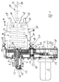
- Fig.1 the device is in its one wheel brake actuating brake position.
- the device has an electric motor 1 with a motor drive shaft 2.
- the motor drive shaft 2 is with a first gear 3 of a reduction gear non-rotatably connected.
- the reduction gear contains a total of four gears, with a second gear 4 is rotatably connected to a third gear 5 and that fourth gear 6 with the spindle nut 7 of a spindle drive is rotatably connected.
- Spindle 8 is one in the direction of movement 9 in the form of a Piston rod trained coupling member 10 linearly movable.
- the coupling member 10 axially supports the spindle 8 on it opposite free ends a clevis 11 with two across to the drawing sheet plane aligned bearing eyes 12 for Articulation of a brake tensioning mechanism, not shown here.
- the movement lock in the release position of the coupling member 10 can with the existing power supply by the electrical Switch and alternatively manual, i.e. mechanically canceled become. In the event of a power failure, the movement lock can only be operated manually To get picked up.
- the compression spring 13 can then relax and automatically transfers the coupling member 10 into its Braking position according to Fig.1. This braking process can be carried out Current also by exciting the electric motor 1 with a corresponding drive of the motor drive shaft 2 supported become.
- the pressure spring 13 is further relaxed by prevents a limiting web 21 arranged on the housing part 20, when the piston rim 18 bears against the limiting web 21.
- the Limiting web is preferably ring-shaped or radial spreadable expansion ring formed.
- the exemplary embodiment is the piston rim 18 also spaced from the limiting web 21 in the braking position. This reliably ensures that the brake tensioning mechanism is fully cocked in the braking position, i.e. one maximum blocking effect of the wheel brake is given. Another The compression spring 13 is then released by the brake tensioning mechanism prevented.
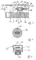
- the mechanical movement lock is carried out by a locking device 22, which is a locking element in the form of a pivotable Pawl 23 contains, as shown in Fig.3 and Fig.4 is.
- the pawl 23 is located there due to the spring force or restoring force of a torsion spring 24 in its locked position, i.e. in engagement with a radially external toothed Ratchet wheel 25.
- One leg of the torsion spring is supported 24 on one housing part 26 of the device, while the other Leg with its bent free end in a ratchet groove 27 of the pawl 23 is inserted.
- the pawl 23 and the Torsion spring 24 are mounted on an axle bolt 28, which is fixed on the housing part 26.
- the pawl 23 is transverse to its swivel plane on both sides each covered by a plate-shaped guide arm 29.
- the two identical guide arms 29 are firmly connected to the pawl 23 and from each other spaced that they are in the locked position of the pawl 23rd touch the ratchet wheel 25 with play.
- the pawl 23 is flush in the locking position on the rear flank 30 of a ratchet tooth 31 of the ratchet wheel 25 and flush with the front flank 32 of the adjacent ratchet tooth 31 on.
- the pawl 23 is in the form of an electromagnet Solenoid 33 mechanically coupled and here with an articulated arm 34 movably connected (Fig. 6).
- the articulated arm 34 in turn is firmly connected to a magnetic armature 35.
- the articulated arm 34 carries two connecting plates arranged opposite one another 36, which is penetrated by an elongated hole 37 are.
- the elongated holes 37 are used to guide the movement of the Guide arm 29 with the ratchet 23 connecting fixing rivets 38.
- the elongated holes 37 enable unobstructed access Mobility between pawl 23 and solenoid 33 during operation.
- Another fixing rivet 38 fixes the connecting plates 36 on the articulated arm 34.
- the connecting plates 36 either connected to the articulated arm 34 or for improved relative mobility between armature 35 and pawl 23 be pivotally connected.
- the axial end of the spindle 8 facing the rod head 15 carries a spindle stub 39 which is approximately flush with a corresponding one Form recess of the rod head 15 engages (Fig.7).
- the spindle stub 39 and the rod head 15 are of one Securing pin 40 running transversely to the direction of movement 9 enforced. This results in a particularly safe mechanical Coupling between coupling member 10 and spindle 8. A accidental decoupling is effectively prevented. Moreover can occur through this coupling without further measures a torque on the spindle 8 prevented (torque lock) because the brake tensioning mechanism usually already has rotational movements of the coupling member 10 about its central longitudinal axis 59 suppressed.
- this is the rod head 15 facing axial end or the spindle stub 39 of the spindle 8 rounded, with the convex side of the fillet on the rod head 15 is present.
- This rounding advantageously enables one movable coupling between spindle 8 and coupling member 10 such that pivoting movements forced by the brake tensioning mechanism of the coupling member 10 is not transferred to the spindle 8 become.
- the spindle drive 7,8 and the gear 2,3,4,5,6 are therefore particularly well protected against wear.
- a possible Pivotal movement of the coupling member 10 is in Fig.2 means the central longitudinal axis offset by a swivel angle w 59 'indicated.
- the end of the spindle stub 39 axially opposite Spindle 8 carries a bearing stub 41, which is in a U-shaped Spindle bearing 42 is inserted.
- the U-legs of the spindle bearing 42 and the bearing stub 41 are together by a fixing screw 43 penetrates, which corresponds to a fixing nut 44.
- the spindle bearing 42 lies in a housing shaft 45 which is carried by the first housing part 26.
- support bearing 46 in particular in the form a ball bearing, the spindle 8 is supported in the housing shaft 45 and at the same time relatively movable relative to the housing shaft 45.
- This mounting of the spindle 8 ensures that the spindle 8 only rotates in the direction of motion 9 becomes.
- An additional rotation test coupling between spindle 8 and coupling member 10 is then not absolutely necessary. Much more is a mechanically contacting system of the spindle 8 the rod head 15 sufficient.
- the first housing part 26 takes the reduction gear, the Spindle drive and the motor drive shaft 2. Besides, is the housing of the electric motor 1 on the first housing part 26 fixed in place, namely screwed.
- the first housing part 26 itself consists of several components, which are firmly connected to one another by screw connections.
- the second housing part 20 is a partial housing of a conventional one Brake cylinder, its cylinder cover and possibly its Membrane has been removed.
- the second housing part 20 pot-shaped with one transverse to the direction of movement 9 running pot bottom 47, the central of a through hole 48 is penetrated for the coupling member 10.
- Pot collar 49 acts as an investment for flush installation of the first housing part 26.
- the first housing part carries 26 an annular ring 50 which is closed in itself, which lies flush against the inside of the pot collar 49.
- the two housing parts 20, 26 are in by means of a clamping means Form of a strap or a clamp 51 with each other releasably connected, this clamping means also from the conventional brake cylinder can come.
- the both ends of the clamping device by screwing together releasably connected.
- the device is analogous to a conventional one Brake cylinder attached to the vehicle.
- the ratchet wheel 25 is the motor drive shaft 2 and the first gear 3 rotatably with each other connected.
- the ratchet 25 and the first gear 3 by one anti-rotation pin or several anti-rotation pins connected by a pin axis 52 of an anti-rotation pin is indicated.
- the pin axis 53 of an anti-rotation pin indicates the secure connection between the second Gear 4 and third gear 5.
- the two are Gears 4.5 on a shaft 54 on a deep groove ball bearing 55 rotatably mounted.
- the spindle nut 7 is by means of a Angular contact ball bearing 56 and at the same time by means of the spring force of Compression spring 13 stably supported in the first housing part 26.
- the device works with current as follows: An electrical Switching device is actuated so that the solenoid 33 is activated becomes. Its magnet armature 35 pulls through the generated magnetic force the pawl 33 from that shown in Fig.3 and Fig.4 Locked position. The movement lock for that Ratchet wheel 25 is due to the restoring force of the torsion spring 24 reversibly canceled, i.e. the movement lock is through the spring force of the torsion spring 24 is automatically restored, as soon as the solenoid 33 is deactivated.
- the elongated holes offer 37 the advantage that the articulated arm 34 in its deactivated 4 can remain when the pawl 23rd from the ratchet wheel 25 rotating in the direction of rotation 60 from its Locked position is pivoted out. Mechanical damage of pawl 23 and solenoid 35 are thus avoided.
- a braking operation by mechanical actuation of the locking device 22 is possible as follows: on the magnet armature 35 a transmission means in the form of a traction cable 57 is fastened, which leads to the area of the driver's seat and there with an actuator (e.g. handle) for manual actuation of the armature 35 is connected. Pulling on the actuator replaces the electromagnetic attraction of the magnet armature 35 and leads in the same way to lifting the movement lock. The compression spring 13 can therefore relax the coupling member 10 is automatically in the braking position Fig.1 transferred. After releasing the actuator the pawl 23 due to the restoring force of the torsion spring 24 automatically transferred to its locked position again. The The braking position is mechanically locked.
Landscapes
- Engineering & Computer Science (AREA)
- Mechanical Engineering (AREA)
- Transportation (AREA)
- General Engineering & Computer Science (AREA)
- Braking Arrangements (AREA)
Applications Claiming Priority (2)
| Application Number | Priority Date | Filing Date | Title |
|---|---|---|---|
| DE19833304 | 1998-07-24 | ||
| DE19833304A DE19833304A1 (de) | 1998-07-24 | 1998-07-24 | Vorrichtung zur Bremsenbetätigung |
Publications (3)
| Publication Number | Publication Date |
|---|---|
| EP0974506A2 true EP0974506A2 (fr) | 2000-01-26 |
| EP0974506A3 EP0974506A3 (fr) | 2002-08-28 |
| EP0974506B1 EP0974506B1 (fr) | 2006-07-26 |
Family
ID=7875142
Family Applications (1)
| Application Number | Title | Priority Date | Filing Date |
|---|---|---|---|
| EP99111387A Expired - Lifetime EP0974506B1 (fr) | 1998-07-24 | 1999-06-11 | Dispositif d'actionnement de frein |
Country Status (5)
| Country | Link |
|---|---|
| US (1) | US6267207B1 (fr) |
| EP (1) | EP0974506B1 (fr) |
| JP (1) | JP3235026B2 (fr) |
| DE (2) | DE19833304A1 (fr) |
| ES (1) | ES2268816T3 (fr) |
Cited By (6)
| Publication number | Priority date | Publication date | Assignee | Title |
|---|---|---|---|---|
| EP1203895A3 (fr) * | 2000-11-03 | 2003-11-05 | Siemens Aktiengesellschaft | Frein à disque actionné électromécaniquement avec frein de stationnement |
| DE102009060626A1 (de) | 2009-12-24 | 2011-06-30 | Klapproth, Holger, Dr., 79108 | Kalibrierte Flusszelle zur IR-Analytik |
| EP3275748A1 (fr) * | 2016-07-25 | 2018-01-31 | LG Innotek Co., Ltd. | Actionneur de frein de stationnement |
| US9909635B2 (en) | 2015-10-01 | 2018-03-06 | Lg Innotek Co., Ltd. | Parking brake actuator |
| WO2021167941A1 (fr) | 2020-02-17 | 2021-08-26 | Tse Brakes, Inc. | Actionneurs de frein à ressort |
| FR3162492A1 (fr) | 2024-05-21 | 2025-11-28 | Sonceboz Motion Boncourt Sa | Système mécatronique de freinage |
Families Citing this family (28)
| Publication number | Priority date | Publication date | Assignee | Title |
|---|---|---|---|---|
| DE10106377C2 (de) * | 2000-12-19 | 2003-04-17 | Knorr Bremse Systeme | Elektromechanische Bremszuspanneinrichtung |
| AU2002216108A1 (en) | 2000-12-19 | 2002-07-01 | Knorr-Bremse Systeme Fur Schienenfahrzeuge Gmbh | Electromechanical brake applying device |
| SE520255C2 (sv) * | 2000-12-20 | 2003-06-17 | Haldex Brake Prod Ab | Sätt och anordning för servicebromsning |
| JP2002220045A (ja) * | 2001-01-26 | 2002-08-06 | Honda Motor Co Ltd | 電動駐車ブレーキ装置 |
| DE10233673A1 (de) * | 2001-07-31 | 2003-03-20 | Tokico Ltd | Elektrische Bremsvorrichtung |
| DE10148480A1 (de) * | 2001-10-01 | 2003-04-17 | Knorr Bremse Systeme | Feststellbremsvorrichtung und Verfahren zum Ansteuern der Feststellbremse |
| US6561321B1 (en) | 2001-12-18 | 2003-05-13 | Delphi Technologies, Inc. | Electromechanical parking brake |
| SE0104279D0 (en) * | 2001-12-18 | 2001-12-18 | Haldex Brake Prod Ab | A parking brake arrangement in an electrically operated brake |
| JP4254332B2 (ja) * | 2003-04-28 | 2009-04-15 | 株式会社日立製作所 | 電動ディスクブレーキ装置 |
| JP2005114042A (ja) * | 2003-10-08 | 2005-04-28 | Honda Motor Co Ltd | 電動駐車ブレーキ装置 |
| DE10361127C5 (de) * | 2003-12-22 | 2013-10-24 | Brose Fahrzeugteile GmbH & Co. Kommanditgesellschaft, Würzburg | Stelleinrichtung, insbesondere Kraftfahrzeug-Feststellbremse |
| JP4512868B2 (ja) | 2004-03-31 | 2010-07-28 | 日立オートモティブシステムズ株式会社 | 電動ブレーキ装置 |
| KR101179103B1 (ko) * | 2008-02-20 | 2012-09-07 | 주식회사 만도 | 전동식 파킹 브레이크 |
| DE102010019603A1 (de) | 2010-05-05 | 2011-11-10 | Knorr-Bremse Systeme für Nutzfahrzeuge GmbH | Federspeicherbremszylinder mit innerhalb der Speicherfeder angeordnetem Elektromotor |
| ES2412607B1 (es) * | 2013-05-06 | 2014-05-12 | Thyssenkrupp Airport Systems, S.A. | Sistema de parada para la cabina de pasarelas de accionamiento a aeronaves y embarcaciones |
| KR20160011283A (ko) * | 2014-07-21 | 2016-02-01 | 현대모비스 주식회사 | 전자식 주차 브레이크 장치 |
| CN105465246A (zh) * | 2014-08-20 | 2016-04-06 | 上海康达医学科技有限公司 | 一种手拉式刹车系统 |
| KR102258684B1 (ko) * | 2014-11-14 | 2021-05-31 | 현대모비스 주식회사 | 전자식 주차 브레이크 장치 |
| WO2016174587A1 (fr) * | 2015-04-27 | 2016-11-03 | Freni Brembo S.P.A. | Dispositif de verrouillage d'un étrier de frein à commande électromagnétique, étrier de frein comprenant ledit étrier, et procédé permettant d'actionner ledit étrier |
| DE102018123042A1 (de) * | 2018-09-19 | 2020-03-19 | Fte Automotive Gmbh | Elektrischer Kupplungsaktuator mit federbelastetem Druckstück |
| CN113631825A (zh) * | 2019-04-22 | 2021-11-09 | 日立安斯泰莫株式会社 | 盘式制动器 |
| KR20210054762A (ko) * | 2019-11-06 | 2021-05-14 | 주식회사 만도 | 파킹 브레이크용 액츄에이터 |
| DE102019008547B3 (de) * | 2019-12-10 | 2021-02-25 | Bundesrepublik Deutschland, vertr. durch das Bundesministerium der Verteidigung, vertr. durch das Bundesamt für Ausrüstung, Informationstechnik und Nutzung der Bundeswehr | Notlöseeinrichtung für Federspeicher-Feststellbremsen militärischer Fahrzeuge |
| DE102021100195B4 (de) | 2021-01-08 | 2022-10-13 | Jungheinrich Aktiengesellschaft | Bremssystem für ein Flurförderzeug |
| EP4357209B1 (fr) * | 2022-10-21 | 2025-10-22 | ZF CV Systems Global GmbH | Actionneur de frein électromécanique pour système de freinage électromécanique |
| US12606130B2 (en) | 2023-06-01 | 2026-04-21 | ZF Active Safety US Inc. | Electromechanical brake for vehicle |
| EP4523984A1 (fr) * | 2023-09-12 | 2025-03-19 | KNORR-BREMSE Systeme für Nutzfahrzeuge GmbH | Actionneur de frein électromécanique pour frein de véhicule |
| DE102023129608A1 (de) * | 2023-10-26 | 2025-04-30 | Svm Schultz Verwaltungs-Gmbh & Co. Kg | Elektromagnet und Verriegelungsanordnung mit Elektromagnet und federvorgespanntem Rastmittel |
Citations (7)
| Publication number | Priority date | Publication date | Assignee | Title |
|---|---|---|---|---|
| DE2546470A1 (de) | 1975-09-22 | 1976-04-29 | Girling Ltd | Fahrzeug-bremsbetaetigungsvorrichtung |
| DE2828385A1 (de) | 1977-06-30 | 1979-01-18 | Bendix Westinghouse Ltd | Bremsenbetaetigungsvorrichtung |
| DE2710585C2 (de) | 1977-03-11 | 1979-02-15 | Raco-Elektro-Maschinen Gmbh, 5830 Schwelm | Bremseinrichtung für Fahrzeuge, insbesondere für Schienenfahrzeuge, mit einem Federspeicher-Bremsgerät |
| DE3048766A1 (de) | 1980-12-23 | 1982-07-15 | Knorr-Bremse GmbH, 8000 München | "zuspannvorrichtung fuer insbesondere feststellbremsen von insbesondere schienenfahrzeugen" |
| DE3344622A1 (de) | 1983-12-09 | 1985-06-20 | Knorr-Bremse GmbH, 8000 München | Einrichtung zur verbindung von deckel und zylinder bei membranbremszylindern |
| DE3603145A1 (de) | 1986-02-01 | 1987-08-06 | Bosch Gmbh Robert | Druckmittel-bremszylinder |
| DE4403719C1 (de) | 1994-02-07 | 1995-08-31 | Knorr Bremse Systeme | Elektromechanische Zuspannvorrichtung für Reibungsbremsen |
Family Cites Families (11)
| Publication number | Priority date | Publication date | Assignee | Title |
|---|---|---|---|---|
| BE407283A (fr) * | 1932-09-26 | |||
| US2854954A (en) * | 1956-09-26 | 1958-10-07 | Insley Mfg Corp | Vehicle brake operating mechanism |
| GB1572812A (en) * | 1976-04-02 | 1980-08-06 | Girling Ltd | Brake actuators |
| DE2748540C2 (de) * | 1977-10-28 | 1979-06-13 | Knorr-Bremse Gmbh, 8000 Muenchen | Federspeicherbremszylinder mit mechanischer Loseeinrichtung |
| US4546298A (en) * | 1983-05-12 | 1985-10-08 | Westinghouse Brake & Signal Co. | Electric actuators |
| IN161424B (fr) * | 1983-05-12 | 1987-11-28 | Westinghouse Brake & Signal | |
| GB8428289D0 (en) * | 1984-11-08 | 1984-12-19 | Westinghouse Brake & Signal | Actuator emergency operation |
| FR2610053B1 (fr) * | 1987-01-22 | 1989-03-31 | Bendix France | Procede et dispositif d'actionnement d'un mecanisme de freinage par un moteur electrique rotatif |
| US5219049A (en) * | 1991-06-24 | 1993-06-15 | General Motors Corporation | Electrically actuated electric brake with adjuster |
| US5348123A (en) * | 1991-09-02 | 1994-09-20 | Akebono Brake Industry Co., Ltd. | Brake actuating apparatus for a vehicle |
| US5180038A (en) * | 1992-01-24 | 1993-01-19 | Orscheln Co. | Electronically controlled parking brake system |
-
1998
- 1998-07-24 DE DE19833304A patent/DE19833304A1/de not_active Withdrawn
-
1999
- 1999-06-11 EP EP99111387A patent/EP0974506B1/fr not_active Expired - Lifetime
- 1999-06-11 ES ES99111387T patent/ES2268816T3/es not_active Expired - Lifetime
- 1999-06-11 DE DE59913698T patent/DE59913698D1/de not_active Expired - Fee Related
- 1999-07-21 JP JP23588099A patent/JP3235026B2/ja not_active Expired - Fee Related
- 1999-07-26 US US09/360,334 patent/US6267207B1/en not_active Expired - Fee Related
Patent Citations (7)
| Publication number | Priority date | Publication date | Assignee | Title |
|---|---|---|---|---|
| DE2546470A1 (de) | 1975-09-22 | 1976-04-29 | Girling Ltd | Fahrzeug-bremsbetaetigungsvorrichtung |
| DE2710585C2 (de) | 1977-03-11 | 1979-02-15 | Raco-Elektro-Maschinen Gmbh, 5830 Schwelm | Bremseinrichtung für Fahrzeuge, insbesondere für Schienenfahrzeuge, mit einem Federspeicher-Bremsgerät |
| DE2828385A1 (de) | 1977-06-30 | 1979-01-18 | Bendix Westinghouse Ltd | Bremsenbetaetigungsvorrichtung |
| DE3048766A1 (de) | 1980-12-23 | 1982-07-15 | Knorr-Bremse GmbH, 8000 München | "zuspannvorrichtung fuer insbesondere feststellbremsen von insbesondere schienenfahrzeugen" |
| DE3344622A1 (de) | 1983-12-09 | 1985-06-20 | Knorr-Bremse GmbH, 8000 München | Einrichtung zur verbindung von deckel und zylinder bei membranbremszylindern |
| DE3603145A1 (de) | 1986-02-01 | 1987-08-06 | Bosch Gmbh Robert | Druckmittel-bremszylinder |
| DE4403719C1 (de) | 1994-02-07 | 1995-08-31 | Knorr Bremse Systeme | Elektromechanische Zuspannvorrichtung für Reibungsbremsen |
Cited By (7)
| Publication number | Priority date | Publication date | Assignee | Title |
|---|---|---|---|---|
| EP1203895A3 (fr) * | 2000-11-03 | 2003-11-05 | Siemens Aktiengesellschaft | Frein à disque actionné électromécaniquement avec frein de stationnement |
| DE102009060626A1 (de) | 2009-12-24 | 2011-06-30 | Klapproth, Holger, Dr., 79108 | Kalibrierte Flusszelle zur IR-Analytik |
| US9909635B2 (en) | 2015-10-01 | 2018-03-06 | Lg Innotek Co., Ltd. | Parking brake actuator |
| EP3275748A1 (fr) * | 2016-07-25 | 2018-01-31 | LG Innotek Co., Ltd. | Actionneur de frein de stationnement |
| WO2021167941A1 (fr) | 2020-02-17 | 2021-08-26 | Tse Brakes, Inc. | Actionneurs de frein à ressort |
| EP4107041A4 (fr) * | 2020-02-17 | 2024-02-28 | TSE Brakes, Inc. | Actionneurs de frein à ressort |
| FR3162492A1 (fr) | 2024-05-21 | 2025-11-28 | Sonceboz Motion Boncourt Sa | Système mécatronique de freinage |
Also Published As
| Publication number | Publication date |
|---|---|
| JP2000055092A (ja) | 2000-02-22 |
| JP3235026B2 (ja) | 2001-12-04 |
| DE59913698D1 (de) | 2006-09-07 |
| EP0974506B1 (fr) | 2006-07-26 |
| ES2268816T3 (es) | 2007-03-16 |
| US6267207B1 (en) | 2001-07-31 |
| EP0974506A3 (fr) | 2002-08-28 |
| DE19833304A1 (de) | 2000-02-10 |
Similar Documents
| Publication | Publication Date | Title |
|---|---|---|
| EP0974506B1 (fr) | Dispositif d'actionnement de frein | |
| EP2272692B1 (fr) | Attelage de remorque | |
| AT512710B1 (de) | Antriebseinheit mit einer elektrischen maschine | |
| DE69930760T2 (de) | Handgriff für feststellbremsbedienung | |
| DE4129934A1 (de) | Feststellbremsanlage fuer personenkraftwagen | |
| EP0975497A1 (fr) | Frein de stationnement pour vehicules | |
| DE4403574C1 (de) | Antriebsvorrichtung für ein zwischen Endstellungen verstellbares Teil eines Fahrzeuges | |
| DE2710585B1 (de) | Bremseinrichtung fuer Fahrzeuge,insbesondere fuer Schienenfahrzeuge,mit einem Federspeicher-Bremsgeraet | |
| DE69934417T2 (de) | Vorrichtung an einem betätigungshandgriff einer feststellbremse | |
| EP1679456A1 (fr) | Verrouillage de sécurité en particulier pour le frein de parcage des transmissions automatiques | |
| DE19705105C2 (de) | Fremdkraftunterstützte Betätigungseinrichtung für eine Feststellbremse für Fahrzeuge | |
| DE60021856T2 (de) | Kraftangetriebene türverriegelungsvorrichtung | |
| DE3827418A1 (de) | Schliesszylinder | |
| DE4205588A1 (de) | Feststellbremsanlage | |
| EP2657051A1 (fr) | Agencement de couplage pour un support de toit | |
| DE19726188B4 (de) | Feststellbremse für Kraftfahrzeuge | |
| DE19532590B4 (de) | Motor- und handbetätigbarer Stellantrieb | |
| EP0966381B1 (fr) | Dispositif d'actionnement auxiliaire pour un systeme de frein de stationnement a actionnement electromecanique | |
| DE10157462A1 (de) | Feststellbremse | |
| EP2093110B1 (fr) | Frein de stationnement | |
| EP3879138B1 (fr) | Système de verrouillage du parking | |
| DE19832502C2 (de) | Türfeststeller | |
| DE3743808C2 (fr) | ||
| EP2078126B1 (fr) | Dispositif d'actionnement électromécanique pour battant ou analogue | |
| EP2308729B1 (fr) | Véhicule, notamment véhicule électrique, doté d'un frein de stationnement électrique |
Legal Events
| Date | Code | Title | Description |
|---|---|---|---|
| PUAI | Public reference made under article 153(3) epc to a published international application that has entered the european phase |
Free format text: ORIGINAL CODE: 0009012 |
|
| AK | Designated contracting states |
Kind code of ref document: A2 Designated state(s): AT BE CH CY DE DK ES FI FR GB GR IE IT LI LU MC NL PT SE |
|
| AX | Request for extension of the european patent |
Free format text: AL;LT;LV;MK;RO;SI |
|
| EUG | Se: european patent has lapsed | ||
| PUAL | Search report despatched |
Free format text: ORIGINAL CODE: 0009013 |
|
| AK | Designated contracting states |
Kind code of ref document: A3 Designated state(s): AT BE CH CY DE DK ES FI FR GB GR IE IT LI LU MC NL PT SE |
|
| AX | Request for extension of the european patent |
Free format text: AL;LT;LV;MK;RO;SI |
|
| RIC1 | Information provided on ipc code assigned before grant |
Free format text: 7B 60T 13/74 A, 7F 16D 65/34 B, 7B 60T 7/10 B |
|
| 17P | Request for examination filed |
Effective date: 20030225 |
|
| AKX | Designation fees paid |
Designated state(s): DE ES FR GB IT NL SE |
|
| 17Q | First examination report despatched |
Effective date: 20050517 |
|
| GRAP | Despatch of communication of intention to grant a patent |
Free format text: ORIGINAL CODE: EPIDOSNIGR1 |
|
| GRAS | Grant fee paid |
Free format text: ORIGINAL CODE: EPIDOSNIGR3 |
|
| GRAA | (expected) grant |
Free format text: ORIGINAL CODE: 0009210 |
|
| AK | Designated contracting states |
Kind code of ref document: B1 Designated state(s): DE ES FR GB IT NL SE |
|
| PG25 | Lapsed in a contracting state [announced via postgrant information from national office to epo] |
Ref country code: IT Free format text: LAPSE BECAUSE OF FAILURE TO SUBMIT A TRANSLATION OF THE DESCRIPTION OR TO PAY THE FEE WITHIN THE PRESCRIBED TIME-LIMIT;WARNING: LAPSES OF ITALIAN PATENTS WITH EFFECTIVE DATE BEFORE 2007 MAY HAVE OCCURRED AT ANY TIME BEFORE 2007. THE CORRECT EFFECTIVE DATE MAY BE DIFFERENT FROM THE ONE RECORDED. Effective date: 20060726 |
|
| REG | Reference to a national code |
Ref country code: GB Ref legal event code: FG4D Free format text: NOT ENGLISH |
|
| REG | Reference to a national code |
Ref country code: SE Ref legal event code: TRGR |
|
| GBT | Gb: translation of ep patent filed (gb section 77(6)(a)/1977) |
Effective date: 20060726 |
|
| REF | Corresponds to: |
Ref document number: 59913698 Country of ref document: DE Date of ref document: 20060907 Kind code of ref document: P |
|
| REG | Reference to a national code |
Ref country code: SE Ref legal event code: RPOT |
|
| ET | Fr: translation filed | ||
| REG | Reference to a national code |
Ref country code: ES Ref legal event code: FG2A Ref document number: 2268816 Country of ref document: ES Kind code of ref document: T3 |
|
| RAP2 | Party data changed (patent owner data changed or rights of a patent transferred) |
Owner name: DAIMLERCHRYSLER AG |
|
| PLBE | No opposition filed within time limit |
Free format text: ORIGINAL CODE: 0009261 |
|
| STAA | Information on the status of an ep patent application or granted ep patent |
Free format text: STATUS: NO OPPOSITION FILED WITHIN TIME LIMIT |
|
| NLT2 | Nl: modifications (of names), taken from the european patent patent bulletin |
Owner name: DAIMLERCHRYSLER AG Effective date: 20070502 |
|
| 26N | No opposition filed |
Effective date: 20070427 |
|
| EUG | Se: european patent has lapsed | ||
| GBPC | Gb: european patent ceased through non-payment of renewal fee |
Effective date: 20070611 |
|
| NLV4 | Nl: lapsed or anulled due to non-payment of the annual fee |
Effective date: 20080101 |
|
| REG | Reference to a national code |
Ref country code: FR Ref legal event code: ST Effective date: 20080229 |
|
| PG25 | Lapsed in a contracting state [announced via postgrant information from national office to epo] |
Ref country code: NL Free format text: LAPSE BECAUSE OF NON-PAYMENT OF DUE FEES Effective date: 20080101 Ref country code: DE Free format text: LAPSE BECAUSE OF NON-PAYMENT OF DUE FEES Effective date: 20080101 |
|
| PG25 | Lapsed in a contracting state [announced via postgrant information from national office to epo] |
Ref country code: GB Free format text: LAPSE BECAUSE OF NON-PAYMENT OF DUE FEES Effective date: 20070611 |
|
| PG25 | Lapsed in a contracting state [announced via postgrant information from national office to epo] |
Ref country code: SE Free format text: LAPSE BECAUSE OF NON-PAYMENT OF DUE FEES Effective date: 20070612 |
|
| REG | Reference to a national code |
Ref country code: ES Ref legal event code: FD2A Effective date: 20070612 |
|
| PG25 | Lapsed in a contracting state [announced via postgrant information from national office to epo] |
Ref country code: FR Free format text: LAPSE BECAUSE OF NON-PAYMENT OF DUE FEES Effective date: 20070702 |
|
| PG25 | Lapsed in a contracting state [announced via postgrant information from national office to epo] |
Ref country code: ES Free format text: LAPSE BECAUSE OF NON-PAYMENT OF DUE FEES Effective date: 20070612 |