EP0974721A2 - Mehrriegelschloss - Google Patents
Mehrriegelschloss Download PDFInfo
- Publication number
- EP0974721A2 EP0974721A2 EP99890205A EP99890205A EP0974721A2 EP 0974721 A2 EP0974721 A2 EP 0974721A2 EP 99890205 A EP99890205 A EP 99890205A EP 99890205 A EP99890205 A EP 99890205A EP 0974721 A2 EP0974721 A2 EP 0974721A2
- Authority
- EP
- European Patent Office
- Prior art keywords
- lock
- push rod
- change lever
- driver
- pin
- Prior art date
- Legal status (The legal status is an assumption and is not a legal conclusion. Google has not performed a legal analysis and makes no representation as to the accuracy of the status listed.)
- Granted
Links
- 238000006073 displacement reaction Methods 0.000 claims description 7
- 230000005540 biological transmission Effects 0.000 claims description 4
- 238000010276 construction Methods 0.000 description 3
- 238000000034 method Methods 0.000 description 3
- 206010000210 abortion Diseases 0.000 description 1
- 231100000176 abortion Toxicity 0.000 description 1
- 230000000881 depressing effect Effects 0.000 description 1
- 230000000694 effects Effects 0.000 description 1
- 210000003127 knee Anatomy 0.000 description 1
- 238000009420 retrofitting Methods 0.000 description 1
Images

Classifications
-
- E—FIXED CONSTRUCTIONS
- E05—LOCKS; KEYS; WINDOW OR DOOR FITTINGS; SAFES
- E05C—BOLTS OR FASTENING DEVICES FOR WINGS, SPECIALLY FOR DOORS OR WINDOWS
- E05C9/00—Arrangements of simultaneously actuated bolts or other securing devices at well-separated positions on the same wing
- E05C9/02—Arrangements of simultaneously actuated bolts or other securing devices at well-separated positions on the same wing with one sliding bar for fastening when moved in one direction and unfastening when moved in opposite direction; with two sliding bars moved in the same direction when fastening or unfastening
- E05C9/021—Arrangements of simultaneously actuated bolts or other securing devices at well-separated positions on the same wing with one sliding bar for fastening when moved in one direction and unfastening when moved in opposite direction; with two sliding bars moved in the same direction when fastening or unfastening with rack and pinion mechanism
- E05C9/023—Arrangements of simultaneously actuated bolts or other securing devices at well-separated positions on the same wing with one sliding bar for fastening when moved in one direction and unfastening when moved in opposite direction; with two sliding bars moved in the same direction when fastening or unfastening with rack and pinion mechanism between a lock cylinder and the bar
-
- E—FIXED CONSTRUCTIONS
- E05—LOCKS; KEYS; WINDOW OR DOOR FITTINGS; SAFES
- E05B—LOCKS; ACCESSORIES THEREFOR; HANDCUFFS
- E05B59/00—Locks with latches separate from the lock-bolts or with a plurality of latches or lock-bolts
Definitions
- the invention relates to a multi-bolt lock with key actuation and a gear transmission between the lock cylinder and a toothing of at least one locking actuating push rod or a push rod connecting piece, being a gear, especially the abortive Gear, a driver for the actuation of a change lever for withdrawing a lock latch and wherein the change lever is rotatably mounted on the latch side and with its end facing away from the trap in the area of the Driver lies and on the push rod or on one with a control surface of this kinematically connected control link to guide the change lever in the turning circle of the Driver when the lock is open or for deflection from this turning circle and thus for exemption the driver when the lock is in the locked position is provided
- the invention aims to provide a retrofittable particularly narrow, simple and reliable To create the lock construction, which a multiple change operation during a locking or unlocking process avoids.
- This is achieved in that the Control link as one in the lock housing in the direction of displacement the push rod guided, coupled with the push rod Slider is formed, which has a control slot, in which a pin of the change lever engages and that the Control slot crosses the change lever and the control slot when closing the lock and thus advancing the Push rod the change lever by means of the pin from the driver takes off and when unlocking and thus retracting the Push the change lever into the path of the driver directs.
- the change lever is disengaged through the control surface, when the multi-bolt lock locks (one-turn, two-turn) and with the actuating element in the lock mechanism, here with the abortive gear or its driver coupled as soon as the lock is open.
- the control takes place depending on the displacement of the Push rod or the push rods with divided, counter-rotating Push rods and is made up of a few components a multi-bolt lock can also be retrofitted. A particularly narrow construction can be realized.
- control slot runs in the direction of displacement of the push rod and has a length that is approximately the displacement of The push rod corresponds to the open position of the Lock corresponding end of the control slot one Exemption for the pivot of the change lever to its unobstructed Retraction movement of the trap is provided. Too a control option for the locking position create, which is that by depressing the Drückers tries whether the door is actually locked or locked is proposed in the area of the locking side End of the control slot a recess for receiving and release of the pin when the latch is actuated the pusher is provided.
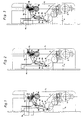
- FIG. 1 shows a Multi-bolt lock only with those for understanding the invention necessary components in principle in unlocked position (Open position), Fig. 2 the lock after 1 when changing, Fig. 3, the lock of Fig. 1st 4 when the handle is actuated, the lock in the locked position and FIG. 5 the lock according to FIG. 4 and control handle actuation.
- a multi-bolt lock according to FIGS. 1 to 5 comprises one Lock cylinder 1 in a lock housing 2.
- a gear 3 is form-fitting with a locking lug of the lock cylinder 1 connected and takes over the rotary movement of a key in the Lock cylinder around them via a gear 4 as a linear movement a push rod (not shown) and ultimately as Extension or withdrawal movement to several bars, including also to be transmitted to the bolt 5 in the lock housing 2.
- the abortive gear 6 of the transmission 4 has a double function. It not only takes over the power transmission to the Push rod or the push rods, but it also carries one Driver 7, here for example designed as a pin. 1, a change lever is based on the driver 7 8 from the other end in the knee of an angle lever 9 is pivoted.
- the angle lever 9 has a fixed pivot point 10 and via a pin 11 which in an elongated hole 12 of a falling shaft 13 engages.
- the trap 14 is withdrawn against spring force (spring not shown), when the gear 6 moves clockwise. It the change lever 8 is then raised (as shown in FIG. 2 and there) pivoted by the angle lever 9, the latter the Trap 14 pulls back over the pin-slot connection. This Movement of the gear 6 results from further turning the key in the cylinder after unlocking if without The door should be opened manually.
- Fig. 1 also shows a control link 15, which as Slider is formed and form-fitting with the push rod connected is.
- the control link 15 makes each Movement of the push rod up and down to the locking position or in the open position with.
- the control backdrop 15 has a control slot 16 in which a pin 17 of the change lever 8 engages. The one described above 2 actuation moves the pin 17 in Slot 16 to the top right.
- the slot 16 is designed that it is exactly the path of the pin 17 in the position 2 follows.
- Fig. 3 shows the handle actuation of the multi-bolt lock.
- the gear 6 remains in the position shown in FIG Handle, a follower 18 and the angle lever is the Trap withdrawn, with the pin 17 as in Fig. 2 moves freely in the control slot 16.
- the change lever 8 remains disengaged as long as the bolt 5 is pushed out, no matter what angle of rotation that Gear 6 describes.
- the pin 7 then moves next to the End of the change lever 8 over. Only when completely again unlocked and the control link 15 together with the push rod pushed down and the bolt 5 is retracted (Fig. 1) gives away the control surface in the control slot 16 by their downward movement over the pin 17 the change lever 8 to the right in the lane of the driver 7, on which the saddle-shaped end of the change lever 8 rides out. If you turn the key further than unlocking it 2 results, that is, the effect of Exchange lever 8 with retraction of the latch 14.
- Fig. 5 shows the locked position with two-speed extended Bolt 5 (similar to Fig. 4) again. Even in this position should it be possible to retract the trap 14 to to be able to check whether the lock is actually locked is. This is done by actuating the lever handle 18 and the angle lever 9. The control link 15 moves not, but the change lever 8 is by the angle lever 9 pulled up to the right. This would be because of a collision the lower end of the change lever 8 with the faceplate wall not easily possible, the control slot 16 would not have a recess 19 in the pin 17 when the handle is actuated and immersed locked lock.
Landscapes
- Engineering & Computer Science (AREA)
- Mechanical Engineering (AREA)
- Lock And Its Accessories (AREA)
- Arrangement Or Mounting Of Control Devices For Change-Speed Gearing (AREA)
Abstract
Description
Claims (3)
- Mehrriegelschloss mit Schlüsselbetätigung und einem Zahnradgetriebe zwischen dem Schließzylinder und einer Verzahnung mindestens einer die Verriegelung betätigenden Schubstange oder eines Schubstangenanschlussstückes, wobei ein Zahnrad, insbesondere das abtreibende Zahnrad, einen Mitnehmer für die Betätigung eines Wechselhebels für das Zurückziehen einer Schlossfalle aufweist und wobei der Wechselhebel fallenseitig drehbar gelagert ist und mit seinem von der Falle abgewandten Ende im Bereich des Mitnehmers liegt und auf der Schubstange oder auf einer mit dieser kinematisch verbundenen Steuerkulisse eine Steuerfläche zur Führung des Wechselhebels in den Drehkreis des Mitnehmers bei Offenstellung der Verriegelung bzw. zum Auslenken aus diesem Drehkreis und somit zur Freistellung gegenüber dem Mitnehmer bei Verschlussstellung der Verriegelung vorgesehen ist, dadurch gekennzeichnet, dass die Steuerkulisse (15) als ein im Schlossgehäuse (2) in Verschieberichtung der Schubstange geführter, mit der Schubstange gekuppelter Schieber ausgebildet ist, der einen Steuerschlitz (16) aufweist, in den ein Zapfen (17) des Wechselhebels (8) eingreift und dass der Steuerschlitz (16) den Wechselhebel (8) kreuzt und der Steuerschlitz (16) beim Schließen der Verriegelung und damit Vorschieben der Schubstange den Wechselhebel (8) mittels des Zapfens (17) von dem Mitnehmer (7) abhebt und beim Entriegeln und damit Zurückziehen der Schubstange den Wechselhebel (8) in die Bahn des Mitnehmers (7) lenkt.
- Mehrriegelschloss nach Anspruch 1, dadurch gekennzeichnet, dass der Steuerschlitz (16) in Verschieberichtung der Schubstange läuft und eine Länge aufweist, die annähernd dem Verschiebeweg der Schubstange entspricht, wobei an dem der Offenstellung der Verriegelung entsprechenden Ende des Steuerschlitzes (16) eine Freistellung für den Zapfen (17) des Wechselhebels (8) zu dessen ungehinderter Rückzugsbewegung der Falle (14) vorgesehen ist.
- Mehrriegelschloss nach den Ansprüchen 1 oder 2, dadurch gekennzeichnet, dass im Bereich des verriegelungsseitigen Endes des Steuerschlitzes (16) eine Ausnehmung (19) zur Aufnahme und Freistellung des Zapfens (17) bei Fallenbetätigung durch den Drücker vorgesehen ist.
Applications Claiming Priority (2)
| Application Number | Priority Date | Filing Date | Title |
|---|---|---|---|
| AT127698 | 1998-07-23 | ||
| AT127698A AT406496B (de) | 1998-07-23 | 1998-07-23 | Mehrriegelschloss |
Publications (3)
| Publication Number | Publication Date |
|---|---|
| EP0974721A2 true EP0974721A2 (de) | 2000-01-26 |
| EP0974721A3 EP0974721A3 (de) | 2002-11-13 |
| EP0974721B1 EP0974721B1 (de) | 2005-03-09 |
Family
ID=3510389
Family Applications (1)
| Application Number | Title | Priority Date | Filing Date |
|---|---|---|---|
| EP19990890205 Expired - Lifetime EP0974721B1 (de) | 1998-07-23 | 1999-06-24 | Mehrriegelschloss |
Country Status (4)
| Country | Link |
|---|---|
| EP (1) | EP0974721B1 (de) |
| AT (1) | AT406496B (de) |
| DE (1) | DE59911721D1 (de) |
| ES (1) | ES2237903T3 (de) |
Cited By (4)
| Publication number | Priority date | Publication date | Assignee | Title |
|---|---|---|---|---|
| EP1197622A3 (de) * | 2000-10-12 | 2003-11-19 | Carl Fuhr GmbH & Co. | Treibstangenverschluss |
| EP1496177A1 (de) * | 2003-07-10 | 2005-01-12 | Roto Frank Ag | Schlüsselbetätigbares Mehrriegelschloss |
| EP1288404A3 (de) * | 2001-08-22 | 2005-06-22 | Roto Frank Eisenwarenfabrik Aktiengesellschaft | Mehrriegelschloss |
| DE202024102203U1 (de) | 2024-04-30 | 2024-05-23 | Kfv Karl Fliether Gmbh & Co. Kg | Kulissenfolger |
Families Citing this family (1)
| Publication number | Priority date | Publication date | Assignee | Title |
|---|---|---|---|---|
| US7946080B2 (en) | 2007-01-29 | 2011-05-24 | Newell Operating Company | Lock assembly |
Citations (1)
| Publication number | Priority date | Publication date | Assignee | Title |
|---|---|---|---|---|
| DE3213452A1 (de) | 1982-04-10 | 1983-10-20 | Carl Fuhr Gmbh & Co, 5628 Heiligenhaus | Treibstangenschloss |
Family Cites Families (4)
| Publication number | Priority date | Publication date | Assignee | Title |
|---|---|---|---|---|
| DE3901296A1 (de) * | 1989-01-18 | 1990-07-26 | Fuhr Carl Gmbh & Co | Treibstangenschloss |
| DE4110557C2 (de) * | 1991-03-30 | 2000-04-27 | Fliether Karl Gmbh & Co | Schloß, insbesondere Einsteckschloß |
| DE9208526U1 (de) * | 1992-06-25 | 1992-09-10 | Gretsch-Unitas GmbH Baubeschläge, 7257 Ditzingen | Schloß, insbesondere Einsteckschloß für eine Außentür |
| DE29608862U1 (de) * | 1996-05-17 | 1997-09-18 | Gretsch-Unitas GmbH Baubeschläge, 71254 Ditzingen | Schloß, insbesondere Einsteckschloß |
-
1998
- 1998-07-23 AT AT127698A patent/AT406496B/de not_active IP Right Cessation
-
1999
- 1999-06-24 DE DE59911721T patent/DE59911721D1/de not_active Expired - Lifetime
- 1999-06-24 ES ES99890205T patent/ES2237903T3/es not_active Expired - Lifetime
- 1999-06-24 EP EP19990890205 patent/EP0974721B1/de not_active Expired - Lifetime
Patent Citations (1)
| Publication number | Priority date | Publication date | Assignee | Title |
|---|---|---|---|---|
| DE3213452A1 (de) | 1982-04-10 | 1983-10-20 | Carl Fuhr Gmbh & Co, 5628 Heiligenhaus | Treibstangenschloss |
Cited By (5)
| Publication number | Priority date | Publication date | Assignee | Title |
|---|---|---|---|---|
| EP1197622A3 (de) * | 2000-10-12 | 2003-11-19 | Carl Fuhr GmbH & Co. | Treibstangenverschluss |
| EP1288404A3 (de) * | 2001-08-22 | 2005-06-22 | Roto Frank Eisenwarenfabrik Aktiengesellschaft | Mehrriegelschloss |
| EP1496177A1 (de) * | 2003-07-10 | 2005-01-12 | Roto Frank Ag | Schlüsselbetätigbares Mehrriegelschloss |
| DE202024102203U1 (de) | 2024-04-30 | 2024-05-23 | Kfv Karl Fliether Gmbh & Co. Kg | Kulissenfolger |
| WO2025228599A1 (de) | 2024-04-30 | 2025-11-06 | Kfv Karl Fliether Gmbh & Co. Kg | Kulissenfolger |
Also Published As
| Publication number | Publication date |
|---|---|
| EP0974721B1 (de) | 2005-03-09 |
| ES2237903T3 (es) | 2005-08-01 |
| AT406496B (de) | 2000-05-25 |
| EP0974721A3 (de) | 2002-11-13 |
| ATA127698A (de) | 1999-10-15 |
| DE59911721D1 (de) | 2005-04-14 |
Similar Documents
| Publication | Publication Date | Title |
|---|---|---|
| EP0619409B1 (de) | Mehrriegelschloss | |
| EP1932989B1 (de) | Schliessanlage für Türen, Fenster oder dergleichen, insbesondere Treibstangenschloss mit Panikfunktion und Mehrpunktverriegelung | |
| EP2951369B1 (de) | Panikschloss | |
| DE3836693A1 (de) | Treibstangenschloss | |
| AT393710B (de) | Mehrriegelverschluss | |
| EP0807736B1 (de) | Schloss, insbesondere Einsteckschloss | |
| EP0861960A2 (de) | Sicherheitsschloss | |
| EP1574644A2 (de) | Schliessanlage für Türen, Fenster oder dergleichen, insbesonde Treibstangenschloss mit Panikfunktion und Mehrpunktverriegelung | |
| EP1020597B1 (de) | Treibstangenverschluss mit einem Hauptschloss und einem Nebenschloss | |
| EP0509217A1 (de) | Mehrriegel-Türschloss | |
| EP2072725A2 (de) | Treibstangenverschluss | |
| EP0575701A1 (de) | Schloss, insbesondere Einsteckschloss für eine Aussentür | |
| EP0799359A1 (de) | Drückerbetätigbares mehrriegelschloss | |
| DE9007232U1 (de) | Treibstangenverschluß | |
| AT406496B (de) | Mehrriegelschloss | |
| EP3045624A1 (de) | Verriegelungsvorrichtung für einen schwenkbar gelagerten flügel | |
| EP3144455B1 (de) | Verriegelungseinrichtung | |
| EP0688930B1 (de) | Schloss für Türen oder Fenster | |
| DE3731879C2 (de) | Schließzylinderbetätigbares Türschloß | |
| EP3805493A2 (de) | Modular aufgebautes schloss mit panikfunktion | |
| EP4116529B1 (de) | Verriegelungseinheit | |
| AT406597B (de) | Mehrriegelschloss mit wechselbetätigung | |
| EP1098057B1 (de) | Zylinderbetätigbarer Mehrriegelverschluss | |
| DE4110557A1 (de) | Schloss, insbesondere einsteckschloss | |
| EP1288404B1 (de) | Mehrriegelschloss |
Legal Events
| Date | Code | Title | Description |
|---|---|---|---|
| PUAI | Public reference made under article 153(3) epc to a published international application that has entered the european phase |
Free format text: ORIGINAL CODE: 0009012 |
|
| AK | Designated contracting states |
Kind code of ref document: A2 Designated state(s): AT BE CH CY DE DK ES FI FR GB GR IE IT LI LU MC NL PT SE |
|
| AX | Request for extension of the european patent |
Free format text: AL;LT;LV;MK;RO;SI |
|
| PUAL | Search report despatched |
Free format text: ORIGINAL CODE: 0009013 |
|
| AK | Designated contracting states |
Kind code of ref document: A3 Designated state(s): AT BE CH CY DE DK ES FI FR GB GR IE IT LI LU MC NL PT SE |
|
| AX | Request for extension of the european patent |
Free format text: AL;LT;LV;MK;RO;SI |
|
| RIC1 | Information provided on ipc code assigned before grant |
Free format text: 7E 05C 9/00 A, 7E 05B 59/00 B, 7E 05C 9/02 B |
|
| 17P | Request for examination filed |
Effective date: 20030430 |
|
| AKX | Designation fees paid |
Designated state(s): DE FR GB IT |
|
| AXX | Extension fees paid |
Extension state: SI Payment date: 20030430 |
|
| RBV | Designated contracting states (corrected) |
Designated state(s): AT BE CH DE FR GB IT LI |
|
| RBV | Designated contracting states (corrected) |
Designated state(s): BE DE ES FR GB IT NL |
|
| 17Q | First examination report despatched |
Effective date: 20031107 |
|
| GRAP | Despatch of communication of intention to grant a patent |
Free format text: ORIGINAL CODE: EPIDOSNIGR1 |
|
| GRAS | Grant fee paid |
Free format text: ORIGINAL CODE: EPIDOSNIGR3 |
|
| GRAA | (expected) grant |
Free format text: ORIGINAL CODE: 0009210 |
|
| AK | Designated contracting states |
Kind code of ref document: B1 Designated state(s): BE DE ES FR GB IT NL |
|
| AX | Request for extension of the european patent |
Extension state: SI |
|
| REG | Reference to a national code |
Ref country code: GB Ref legal event code: FG4D Free format text: NOT ENGLISH |
|
| REG | Reference to a national code |
Ref country code: IE Ref legal event code: FG4D Free format text: GERMAN |
|
| REF | Corresponds to: |
Ref document number: 59911721 Country of ref document: DE Date of ref document: 20050414 Kind code of ref document: P |
|
| GBT | Gb: translation of ep patent filed (gb section 77(6)(a)/1977) |
Effective date: 20050412 |
|
| PGFP | Annual fee paid to national office [announced via postgrant information from national office to epo] |
Ref country code: FR Payment date: 20050510 Year of fee payment: 7 |
|
| PGFP | Annual fee paid to national office [announced via postgrant information from national office to epo] |
Ref country code: GB Payment date: 20050601 Year of fee payment: 7 |
|
| PG25 | Lapsed in a contracting state [announced via postgrant information from national office to epo] |
Ref country code: ES Free format text: LAPSE BECAUSE OF NON-PAYMENT OF DUE FEES Effective date: 20050625 |
|
| PG25 | Lapsed in a contracting state [announced via postgrant information from national office to epo] |
Ref country code: BE Free format text: LAPSE BECAUSE OF NON-PAYMENT OF DUE FEES Effective date: 20050630 |
|
| REG | Reference to a national code |
Ref country code: ES Ref legal event code: FG2A Ref document number: 2237903 Country of ref document: ES Kind code of ref document: T3 |
|
| ET | Fr: translation filed | ||
| PG25 | Lapsed in a contracting state [announced via postgrant information from national office to epo] |
Ref country code: NL Free format text: LAPSE BECAUSE OF NON-PAYMENT OF DUE FEES Effective date: 20060101 |
|
| PLBE | No opposition filed within time limit |
Free format text: ORIGINAL CODE: 0009261 |
|
| STAA | Information on the status of an ep patent application or granted ep patent |
Free format text: STATUS: NO OPPOSITION FILED WITHIN TIME LIMIT |
|
| 26N | No opposition filed |
Effective date: 20051212 |
|
| NLV4 | Nl: lapsed or anulled due to non-payment of the annual fee |
Effective date: 20060101 |
|
| PG25 | Lapsed in a contracting state [announced via postgrant information from national office to epo] |
Ref country code: GB Free format text: LAPSE BECAUSE OF NON-PAYMENT OF DUE FEES Effective date: 20060624 |
|
| REG | Reference to a national code |
Ref country code: ES Ref legal event code: FD2A Effective date: 20050625 |
|
| GBPC | Gb: european patent ceased through non-payment of renewal fee |
Effective date: 20060624 |
|
| REG | Reference to a national code |
Ref country code: FR Ref legal event code: ST Effective date: 20070228 |
|
| BERE | Be: lapsed |
Owner name: *ROTO FRANK EISENWARENFABRIK A.G. Effective date: 20050630 |
|
| PG25 | Lapsed in a contracting state [announced via postgrant information from national office to epo] |
Ref country code: FR Free format text: LAPSE BECAUSE OF NON-PAYMENT OF DUE FEES Effective date: 20060630 |
|
| PGFP | Annual fee paid to national office [announced via postgrant information from national office to epo] |
Ref country code: IT Payment date: 20110624 Year of fee payment: 13 |
|
| PG25 | Lapsed in a contracting state [announced via postgrant information from national office to epo] |
Ref country code: IT Free format text: LAPSE BECAUSE OF NON-PAYMENT OF DUE FEES Effective date: 20120624 |
|
| REG | Reference to a national code |
Ref country code: DE Ref legal event code: R082 Ref document number: 59911721 Country of ref document: DE Representative=s name: DR. RALF KOTITSCHKE, DE Ref country code: DE Ref legal event code: R082 Ref document number: 59911721 Country of ref document: DE Representative=s name: KOTITSCHKE & HEURUNG PARTNERSCHAFT MBB, DE Ref country code: DE Ref legal event code: R082 Ref document number: 59911721 Country of ref document: DE Representative=s name: KOTITSCHKE & HEURUNG PARTNERSCHAFT MBB PATENT-, DE |
|
| PGFP | Annual fee paid to national office [announced via postgrant information from national office to epo] |
Ref country code: DE Payment date: 20160628 Year of fee payment: 18 |
|
| REG | Reference to a national code |
Ref country code: DE Ref legal event code: R119 Ref document number: 59911721 Country of ref document: DE |
|
| PG25 | Lapsed in a contracting state [announced via postgrant information from national office to epo] |
Ref country code: DE Free format text: LAPSE BECAUSE OF NON-PAYMENT OF DUE FEES Effective date: 20180103 |