EP0974731A2 - Verfahren und Vorrichtung zur Aussolung geneigter Lagerstätten - Google Patents
Verfahren und Vorrichtung zur Aussolung geneigter Lagerstätten Download PDFInfo
- Publication number
- EP0974731A2 EP0974731A2 EP99111295A EP99111295A EP0974731A2 EP 0974731 A2 EP0974731 A2 EP 0974731A2 EP 99111295 A EP99111295 A EP 99111295A EP 99111295 A EP99111295 A EP 99111295A EP 0974731 A2 EP0974731 A2 EP 0974731A2
- Authority
- EP
- European Patent Office
- Prior art keywords
- bore
- brine
- cavity
- deposit
- blanket
- Prior art date
- Legal status (The legal status is an assumption and is not a legal conclusion. Google has not performed a legal analysis and makes no representation as to the accuracy of the status listed.)
- Granted
Links
Images

Classifications
-
- E—FIXED CONSTRUCTIONS
- E21—EARTH OR ROCK DRILLING; MINING
- E21B—EARTH OR ROCK DRILLING; OBTAINING OIL, GAS, WATER, SOLUBLE OR MELTABLE MATERIALS OR A SLURRY OF MINERALS FROM WELLS
- E21B43/00—Methods or apparatus for obtaining oil, gas, water, soluble or meltable materials or a slurry of minerals from wells
- E21B43/28—Dissolving minerals other than hydrocarbons, e.g. by an alkaline or acid leaching agent
-
- E—FIXED CONSTRUCTIONS
- E21—EARTH OR ROCK DRILLING; MINING
- E21C—MINING OR QUARRYING
- E21C41/00—Methods of underground or surface mining; Layouts therefor
- E21C41/16—Methods of underground mining; Layouts therefor
Definitions
- the invention relates to a method and a device for controlled Isolation of inclined deposits, preferably from small-scale underground potash deposits.
- the object of the invention is to control highly rich zones of the deposit to solve or to sol, in order to bring the desired raw material maximize minimization of waste or residues at the same time.
- the method according to the invention for the isolation of deposits, in particular inclined deposits provides that a cavity by means of one completed hole (1) and at least one more Well (2), which at least partially follows the collapse of the deposit, is sunk and completed, whereby between the above the bore (1) created cavity and at least one further bore (2) Connection is created and that to cover the in this Cavity (9) located brine a separated from the brine blanket medium (7) is introduced into the cavity, this blanket medium (7) through the holes (1) and (2), which are by means of a blanket pipeline (22) are connected in a pneumatic-hydraulic network being, the level of the brine level in the brine cavity is measured and that after reaching a defined amount of degradation of the The completion or part of the completion of the other Hole (2) withdrawn by a defined amount and the brine process is started again, the brine over the pipe tour of the bore (1) dissipated and the upper level of this further mining cavity in essentially due to the position of the blanket medium (7) above the Brine level is determined.
- the last one in particular is cemented as a completion Pipe tour in a hole and the pipe tours necessary for the solution, that must be installed in the hole, understood.
- the continuous measurement of the brine level has the advantage that in each Controlled the stage of the dissolving process and, if necessary, the Solution process can be corrected.
- Separate management of the brine (16) and the blanket medium (7) advantageously serves the better Control and measurement of the brine level in the bore (1).
- Another advantageous embodiment of the invention provides that in the Bore (1) in a further tube tour (5) a medium for dilution and / or heating the brine is carried out to crystallization on the pipe walls by z. B. to avoid supersaturated solutions otherwise can lead to disruptions to the extraction operations.
- this is to be resolved Deposit area in the bore (2) by means of an injection pipe tour (11) the solvent (12) is fed separately from the blanket medium (7).
- This has the advantage that the injection tube tour is independent of Diameter of the bore can be designed and changed the injection pipe tour of the Solution process can be better controlled without doing this to change the blanket.
- the degradation can be advantageous through the Volume flow of the solvent (12) in the injection tube tour (11) to be controlled.
- the procedure can be under optimal Conditions taking into account the z. B. for the expansion or Withdrawing the completions or part thereof, in particular the injection tube tour (11), necessary above ground Facilities are carried out.
- the execution of one or more of the bores is particularly advantageous (2) as a deflected borehole, since the drilling starting point is more variable can be designed.
- a deflected hole allows the Tracking of the deposit or the deposit body also at Changes in the collapse of the deposit or the offset of the Deposit, for example due to disturbances.
- a gaseous medium is advantageously used as the blanket medium.
- compressed air can be used as particularly suitable, which is a very inexpensive and ecological medium which is available everywhere.
- the measurement of the level of the brine level underground becomes special advantageously by means of a physical measuring device in the bore carried out, since these measurement methods are trouble-free and easy to use and allow continuous measurements and also in a hole can remain permanently installed while the solution is running and thus a continuous control of the brine level or the one to be soled Allow deposit area.
- the solvent (12) can also be at a temperature between 10 and 90 ° C, preferably a temperature between 40 and 60 ° C, in the Deposit. With such a heated solvent the brine process can be controlled or for a selective solution certain, for example potash-rich parts of the deposit are set and thus the degradation, especially the selective degradation, can be optimized.
- the Solvent (12) during brine in the area of the upper part of the Concentrated cavity has the advantage that the below the Areas located in the brine level are mostly only selectively resolved so that the yield of the desired raw material is maximized, a blanket being dispensed with in these areas of the deposit can. This advantage also occurs when saturated or from the outset almost saturated NaCl solutions are used.
- solid Constituents preferably processing residues, secondary crystals, Overburden and drill cuts or mixtures thereof, into the cavity be introduced, which has the advantage that above-ground landfills with these substances are avoided and the cavity is one Secondary use can be supplied, which at the same time has the advantage that To reduce or prevent the risk of possible damage to the mountain.
- the combination according to the invention in the area of the deposit means a completed hole in a isolated cavity and one or more Wells that partially follow the collapse of the deposit and through the defined withdrawal of the brine / blanket level controlled degradation of the The deposit enables the controlled isolation of insignificant incident deposits.
- the device used to carry out the method of isolation inclined deposits consists of a Injection tube tour (11) in a bore (2) for the supply of solvents (12), a tube tour (3) which is arranged in a bore (1) and for Promotion of the raw materials dissolved in the deposit serves, as well as a System for guiding the blanket medium (7), the guiding of the Blanket medium (7) in the hole (1) with the guide of the blanket medium (7) in the bore (2) is connected by a pipe (22).
- the management of the blanket medium (7) in the bore (2) is designed such that the Annulus of the cemented pipe tour (10) and the injection pipe tour (11) is exploited.
- This device enables the deposit to be mined with relatively simple and trouble-free means, so that the degradation can be carried out trouble-free and optimally and inexpensively.
- a further tube tour are arranged in which a dilution and / or heating medium (13) Brine is fed. This prevents the high Saturation of the delivery pipe (4) closes the brine, which inevitably increases Disruption to brine production would result.
- a conductive or capacitive measuring device (14) to measure the brine level in the underground cavity has the Advantage that such measuring devices are trouble-free and reliable work. They can also be in the well during production remain and measure the brine level continuously. The measurement signals are converted to an evaluation or Control device directed.
- the method according to the invention as well as the device according to the invention can be used not only for the extraction of potash salts, but basically for the extraction of mineral salts, in particular also rock salt and magnesium salts for the production of marketable products such as NaCl and MgCl 2 , and for the extraction of sulfates , Carbonates and / or magnesium salts.
- salable by-products such. B. bromine.
- the extraction of these mineral salts leads to marketable products such as B. KCl, NaCl, MgCl 2 , K 2 SO 4 , Na 2 SO 4 , MgSO 4 , Mg (OH), MgO, Na 2 CO 3 and NaHCO 3 .
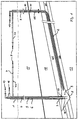
- Figure 1 shows the deposit situation in the preparation phase graphically again
- Figure 2 shows the production phase.
- the potash layer consists of high-percentage Sylvinit 21 with 35 to 40% KCl content and 4 to 5 m thickness and KCl poorer Sylvinit 20 with 5 to 15% KCl content and 6 to 8 m thickness in the lying and hanging area.
- the accompanying minerals of the KCl are mainly NaCl and to a small extent anhydrite. Except for traces, MgCl 2 is completely washed out.
- a double probe is used for the mining of sylvinite according to Figure 1 consisting of a vertical hole 1 and a deflected inclined hole 2 created.
- the distance between the The drilling starting points of the two holes are according to the geological However, the circumstances should and should be at least 100 m in the maximum extent of that technically and economically reasonable effort limited. A distance of 500 m - 2000 m is optimal.
- the extraction of the deposit in terms of sol technology comprises one Preparation phase and a production phase.
- the vertical bore 1 is according to the prior art for the isolation from individual caverns with a cemented pipe tour 3 to the top edge of the potash warehouse and with the concentric installation of two Production tube tours, the outer tube tour 4 and the inner tube tour 5 equipped.
- the annular space 6 between the last cemented route and the outer conveyor tube tour is used to add blanket 7.
- the isolation with Water as a solvent in this hole begins in the horizontal area of the Sylvinite layer 21 with the creation of a cavern sump 8 in direct Driving style and the creation of a cavity 9 by radial Enlargement of the borehole to at least 60 m at a height of 4 - 8 m in indirect driving style.
- the blanket By using the blanket, a Isolation upwards prevented.
- This sol technical undercut of Sylvinite deposit (also called under cut or broad solution) is generally for Creation of a sufficiently large release area necessary and guaranteed with a minimum extension of 60 m, the fluctuations in the Thickness and in the collapse of the high-proof potash layer 21 in the Isolation described below during the production phase in the deflected hole 2 can also be detected.
- the deflected, inclined hole 2 is cut using the latest LWD (logging while drilling) drilling technology within the high-percentage sylvinite layer 21 drilled.
- the good detectability of the K40 isotope can be sufficient precisely follow the collapse of the sylvinite deposit.
- the deflected bore 2 with a cemented pipe tour 10 in the vertical and deflected area completed.
- an injection tube tour 11 to in is in the bore 2 the wide solca 9 of the vertical bore 1 installed.
- Figure 1 gives the Borehole construction and completion of the borehole at the end of the Preparatory phase again.
- the outer annulus 15 of the inclined Bore 2 is with the outer annulus of the vertical bore 1 via a Surface blanket pipeline 22 connected and thus the hydraulic Linking the underground drilling into a system that converts behaves physically like communicating tubes.
- the deflection is carried out Boring the developed area of the sylvinite deposit by circulating of slightly mineralized salt water with approx. 45 g NaCl / l as solvent 12 into the injection tube tour 11. Due to the lower density Compared to the brine in the cavity, the solvent 12 rises to the ridge of the broad sol cavity.
- Withdrawal of blanket 7 became blanket level 14 in both Drilling changed by approx. 3 m upwards compared to the broad sol phase and thus a 3 m thick excavation disc in the inclined hole 2 Isolation released.
- the saturation of the solvent with KCl and NaCl and thus the production of brine 16 takes place on the released Release surfaces.
- the mixing of the solvent 12 at the injection point should be kept low in order to achieve a non-selective dissolution of the deposit in this cavern area. This is achieved by the choice of the diameter of the injection tube tour 11 in relation to the volume flow. It is advantageous to install a 4 1/2 "injection pipe tour 11, as this allows enough variation options for the selection of the volume flow.
- the volume flow is optimized depending on the existing dissolving area in the cavern and should be 10 m 3 / h at the beginning and then gradually can be increased to 50 m 3 / h.
- the brine 16 becomes lowest point of the hydraulic system in the wide sol space 9 of the Flow vertical hole 1.
- a predominantly selective dissolution of the Sylvinites since the brine 16 is already has largely saturated with NaCl in the upper cavern area, but due to the NaCl / KCl ratio in the pending salt rock is still receptive to KCl.
- brine turns 16 by means of the outer tube tour 4 through the built-up cavern pressure conveyed to the surface and further processed.
- the injection pipe tour 11 in the inclined bore 2 withdrawn by a defined length, by the shortest route lead fresh solvent to the top of the cavern. Due to the Incline of the deposit of 10 to 15% means a reduction in the Injection tube tour 11 after every dismantling disc of at least 20 m. For Reduction in the cost of this pipe drawing work should always be possible Complete pipe lengths of the screwed injection pipe tour 11 get extended. In this sense there is also an increase in Dismantling disc up to 4 - 6 m and the extension of approx. 40 m Injection tube tour 11 with no significant negative impact on the full utilization of the deposit possible.
- the pulling force required for the expansion of the injection pipe tour 11 depends next to the length of the inclined borehole from the spill of the injection pipe tour 11 due to residue and secondary crystals in the cavern area from. Since it is ensured that the annular space 15 of the inclined bore 2nd is always filled with blanket 7, only the lower part of the injection tube tour protrudes 11 in the cavern. The spillage of the injection tube tour 11 through residue and the length of the secondary crystals is therefore limited to approx. 3 m. To a very decisive extent, this allows the distances mentioned at the beginning 500 - 2000 m between the two holes 1 and 2.
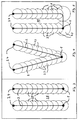
- FIGS. 3 to 5 show variants of the cavern dimensioning in the top view.
- FIG. 3 shows two cavities that are located parallel in the deposit, that of individual mining disks or broad isolation rooms 23, which are offset overlap, exist.
- the inclined or deflected hole 2 is in this example sunk from the drilling point 24 and with the Hole 1 connected.
- the chronological sequence of drilling well 1 and 2 can be varied. After making the connection between the Both holes are followed by gradual removal of individual excavation disks, the selective brining of individual deposits in the marginal areas older disks can still be used.
- the breakdown is controllable by the position of the injection tube tour 11 in the most recent removal disk, the volume flow of the solvent 12, the concentration and Composition of the solvent and the height of the disks.
- Figure 4 shows the combination of two deflected bores 2 of two Drill approach points 24 to create a larger, contiguous cavity to brine in the deposit.
- FIG. 5 shows the total mining of the deposit aimed for by First of all, two caverns, consisting of a number of wide-spread rooms (undercuts) 23, be brought, with one or more pillars 25 remain. Then by connecting the both caverns through a deflected bore also the one between the Caverns located pillars 25 dismantled.
Landscapes
- Engineering & Computer Science (AREA)
- Mining & Mineral Resources (AREA)
- Life Sciences & Earth Sciences (AREA)
- Geology (AREA)
- General Life Sciences & Earth Sciences (AREA)
- Geochemistry & Mineralogy (AREA)
- Physics & Mathematics (AREA)
- Environmental & Geological Engineering (AREA)
- Fluid Mechanics (AREA)
- Remote Sensing (AREA)
- Drilling And Exploitation, And Mining Machines And Methods (AREA)
- Extraction Or Liquid Replacement (AREA)
Abstract
Description
- 1
- vertikale Bohrung
- 2
- abgelenkte Bohrung
- 3
- zementierte Rohrtour von 1
- 4
- äußere Rohrtour
- 5
- innere Rohrtour
- 6
- Ringraum zwischen 3 und 4
- 7
- Blanket-Medium
- 8
- Kavernensumpf
- 9
- Hohlraum
- 10
- zementierte Rohrtour von 2
- 11
- Injektionsrohrtour
- 12
- Lösungsmittel
- 13
- Verdünnungs- oder/und Heizmedium
- 14
- Blanketniveaumessung (kontinuierlich)
- 15
- äußerer Ringraum
- 16
- Sole
- 17
- Deckschicht
- 18
- hängendes Steinsalz
- 19
- liegendes Steinsalz
- 20
- arme Lagerstättenzone
- 21
- hochkonzentrierte Lagerstättenzone
- 22
- Blanketrohrleitung
- 23
- Breitsolungsraum
- 24
- Bohransatzpunkt
- 25
- Stützpfeiler
Claims (21)
- Verfahren zur Aussolung von Lagerstätten, insbesondere geneigter Lagerstätten, dadurch gekennzeichnet, daßa) im Bereich der Lagerstätte ein Hohlraum mittels einer komplettierten Bohrung (1) gesolt wirdb) und mindestens eine weitere Bohrung (2), die zumindest partiell dem Einfallen der Lagerstätte folgt, abgeteuft und komplettiert wird, wobei zwischen dem über der weiteren Bohrung (1) geschaffenen Hohlraum und der weiteren Bohrung (2) eine Verbindung geschaffen wird, undc) daß zur Abdeckung der in dem Hohlraum befindlichen Sole ein von der Sole getrennt geführtes Blanket-Medium (7) in den Hohlraum eingeleitet wird, wobei dieses Blanket-Medium über die Bohrungen (1) und (2), welche mittels einer Blanket-Rohrleitung (22) verbunden sind, in einem pneumatisch-hydraulischen Verbund geführt wird,
wobei das Niveau des Solespiegels des gesolten Hohlraumes gemessen wird, und daßd) nach Erreichen einer definierten Abbaumenge des Rohstoffes die Komplettierung oder ein Teil der Komplettierung der weiteren Bohrung (2) um einen definierten Betrag zurückgezogen wird und der Solvorgang erneut begonnen wird, wobei die Sole über die Rohrtour der Bohrung (1) abgeführt und das obere Niveau dieses weiteren Abbauhohlraumes im wesentlichen durch die Lage des Blanket-Mediums oberhalb des Solespiegels bestimmt wird. - Verfahren nach Anspruch 1, dadurch gekennzeichnet, daß das Niveau des Solespiegels kontinuierlich gemessen wird.
- Verfahren nach Anspruch 1 oder 2, dadurch gekennzeichnet, daß in der komplettierten Bohrung (1) die Sole (16) und das Blanket-Medium (7) getrennt geführt werden.
- Verfahren nach einem der Ansprüche 1 bis 3,
dadurch gekennzeichnet, daß
in der Bohrung (1) in einer weiteren Rohrtour (5) ein Medium zur Verdünnung und/oder Erwärmung der Sole geführt wird. - Verfahren nach einem der Ansprüche 1 bis 4,
dadurch gekennzeichnet, daß
in der Bohrung (2) mittels einer Injektionsrohrtour (11) das Lösungsmittel (12) getrennt von dem Blanket-Medium (7) dem zu solenden Lagerstättenbereich zugeführt wird. - Verfahren nach einem der Ansprüche 1 bis 5,
dadurch gekennzeichnet, daß
der Abstand zwischen den Bohrungen (1) und (2) mehr als 100 m, vorzugsweise zwischen 500 und 2000 m, beträgt. - Verfahren nach einem der Ansprüche 1 bis 6,
dadurch gekennzeichnet, daß
die Bohrung (2) als abgelenkte Bohrung ausgeführt wird. - Verfahren nach einem der Ansprüche 1 bis 7,
dadurch gekennzeichnet, daß
als Blanket-Medium ein gasförmiges Medium, vorzugsweise Druckluft, eingesetzt wird. - Verfahren nach einem der Ansprüche 1 bis 8,
dadurch gekennzeichnet, daß
die Messung des Niveaus des Solespiegels mittels physikalischer Meßeinrichtung in der Bohrung (1) durchgeführt wird. - Verfahren nach einem der Ansprüche 1 bis 9,
dadurch gekennzeichnet, daß
der Verfahrensschritt nach Anspruch 1 d) zwei- oder mehrfach wiederholt durchgeführt wird, wobei der Betrag des Rückzuges der Komplettierung oder eines Teils der Komplettierung der weiteren Bohrung (2) in Abhängigkeit der Lagerstättenmächtigkeit und dem Einfallen der Lagerstätte oder der Bohrung (2) sowie des maximalen Durchmessers des zu solenden Hohlraumes gewählt wird, - Verfahren nach einem der Ansprüche 1 bis 10,
dadurch gekennzeichnet, daß
ein vorkonzentriertes Lösungsmittel (12), vorzugsweise eine NaCl-Lösung, welche vorzugsweise zwischen 40 und 80 g/l NaCl aufweist, zum selektiven Solen der Lagerstätte eingesetzt wird. - Verfahren nach Anspruch 11, dadurch gekennzeichnet, daß als Lösungsmittel (12) eine gesättigte oder nahezu gesättigte Lösung eingesetzt wird.
- Verfahren nach einem der Ansprüche 1 bis 12,
dadurch gekennzeichnet, daß
das Lösungsmittel (12) mit einer Temperatur zwischen 10 und 90 °C, vorzugsweise einer Temperatur von 40 bis 60 °C, in die Lagerstätte eingebracht wird. - Verfahren nach einem der Ansprüche 1 bis 13,
dadurch gekennzeichnet, daß
das Lösungsmittel während des Solens im Bereich des oberen Teils des Hohlraumes aufkonzentriert wird. - Verfahren nach einem der Ansprüche 1 bis 14,
dadurch gekennzeichnet, daß
während des Solens oder nach Abschluß des Solevorganges feste Bestandteile, vorzugsweise Aufbereitungsrückstände, Sekundärkristallisate, Abraum- und Bohrcuttings oder Mischungen hiervon, in den Hohlraum eingebracht werden. - Verfahren, dadurch gekennzeichnet, daß
nach dem Solen zweier oder mehrerer Hohlräume die Zwischenräume zwischen diesen Hohlräumen mittels Verfahren gemäß einem oder mehreren der Ansprüche 1 bis 15 gesolt werden. - Vorrichtung zur Durchführung des Verfahrens zur Aussolung geneigter Lagerstätten, bestehend aus einer Injektionsrohrtour (11) in einer Bohrung (2) zur Zufuhr von Lösungsmittel (12),einer Rohrtour (3) in einer Bohrung (1) zur Förderung der in der Lagerstätte gelösten Rohstoffe sowie einem System zur Führung des Blanket-Mediums (7), wobeidie Führung des Blanket-Mediums (7) in der Bohrung (1) mit der Führung des Blanket-Mediums (7) in der Bohrung (2) durch eine Rohrleitung (22) verbunden ist undeine Meßeinrichtung (14) zur Messung des Solespiegels in dem untertägigen Hohlraum in der Führung des Blanket-Mediums (7) in der Bohrung (1) angeordnet ist.
- Vorrichtung nach Anspruch 17, dadurch gekennzeichnet, daß in der Rohrtour der Bohrung (1), in der die Sole abgeführt wird, eine weitere Rohrtour angeordnet ist, in der ein Verdünnungs- und/oder Heizmedium (13) der Sole zugeführt wird.
- Vorrichtung nach Anspruch 17 oder 18,
dadurch gekennzeichnet, daß
die Führung des Blanket-Mediums (7) in der Bohrung (1) als Ringraum zwischen einer äußeren Rohrtour (4) und einer zementierten Rohrtour (3) ausgebildet ist. - Vorrichtung nach einem der Ansprüche 17 bis 19,
dadurch gekennzeichnet, daß
die Führung des Blanket-Mediums (7) in der Bohrung (2) durch den Ringraum der zementierten Rohrtour (10) und der Injektionsrohrtour (11) ausgebildet ist. - Vorrichtung nach Anspruch 17, dadurch gekennzeichnet, daß eine konduktiv oder kapazitiv arbeitende Meßeinrichtung (14) verwendet wird.
Applications Claiming Priority (2)
| Application Number | Priority Date | Filing Date | Title |
|---|---|---|---|
| DE19831234 | 1998-07-11 | ||
| DE19831234A DE19831234C2 (de) | 1998-07-11 | 1998-07-11 | Verfahren und Vorrichtung zur Aussolung geneigter Lagerstätten |
Publications (3)
| Publication Number | Publication Date |
|---|---|
| EP0974731A2 true EP0974731A2 (de) | 2000-01-26 |
| EP0974731A3 EP0974731A3 (de) | 2001-06-13 |
| EP0974731B1 EP0974731B1 (de) | 2003-12-17 |
Family
ID=7873815
Family Applications (1)
| Application Number | Title | Priority Date | Filing Date |
|---|---|---|---|
| EP99111295A Expired - Lifetime EP0974731B1 (de) | 1998-07-11 | 1999-06-10 | Verfahren und Vorrichtung zur Aussolung geneigter Lagerstätten |
Country Status (3)
| Country | Link |
|---|---|
| EP (1) | EP0974731B1 (de) |
| DE (2) | DE19831234C2 (de) |
| ES (1) | ES2213314T3 (de) |
Cited By (5)
| Publication number | Priority date | Publication date | Assignee | Title |
|---|---|---|---|---|
| US20110175428A1 (en) * | 2010-01-20 | 2011-07-21 | Harvey Haugen | Solution Mining and a Crystallizer for Use Therein |
| CN104847358A (zh) * | 2015-06-08 | 2015-08-19 | 中国科学院青海盐湖研究所 | 杂卤石开采方法 |
| CN107701189A (zh) * | 2017-10-31 | 2018-02-16 | 中国科学院武汉岩土力学研究所 | 高杂质盐矿大型储气库双井建造方法 |
| CN112227985A (zh) * | 2020-10-12 | 2021-01-15 | 中国科学院武汉岩土力学研究所 | 超深盐矿对接井采卤全水平段扩槽方法 |
| WO2021042205A1 (en) * | 2019-09-04 | 2021-03-11 | Inter-Casing Pressure Control Inc. | Inter-casing pressure control systems and methods |
Families Citing this family (3)
| Publication number | Priority date | Publication date | Assignee | Title |
|---|---|---|---|---|
| DE102005055131B4 (de) * | 2005-11-15 | 2009-02-12 | BBC Beratung für Bergbau und Chemie GmbH | Vorrichtung und Verfahren zum Fördern löslicher Bodenschätze durch Solen |
| CN101988385B (zh) * | 2009-08-07 | 2012-07-25 | 中国瑞林工程技术有限公司 | 岩溶大水矿山透气方法 |
| CN111350506A (zh) * | 2020-03-13 | 2020-06-30 | 海南矿业股份有限公司 | 一种采空区顶板处理炮孔布置方法 |
Family Cites Families (5)
| Publication number | Priority date | Publication date | Assignee | Title |
|---|---|---|---|---|
| NL251207A (de) * | 1959-05-07 | |||
| US4290650A (en) * | 1979-08-03 | 1981-09-22 | Ppg Industries Canada Ltd. | Subterranean cavity chimney development for connecting solution mined cavities |
| DE3376275D1 (en) * | 1982-12-13 | 1988-05-19 | Shell Int Research | Blanket-medium/brine interface detection in a solution-mining process |
| US5246273A (en) * | 1991-05-13 | 1993-09-21 | Rosar Edward C | Method and apparatus for solution mining |
| US5431482A (en) * | 1993-10-13 | 1995-07-11 | Sandia Corporation | Horizontal natural gas storage caverns and methods for producing same |
-
1998
- 1998-07-11 DE DE19831234A patent/DE19831234C2/de not_active Expired - Fee Related
-
1999
- 1999-06-10 DE DE59908069T patent/DE59908069D1/de not_active Expired - Fee Related
- 1999-06-10 ES ES99111295T patent/ES2213314T3/es not_active Expired - Lifetime
- 1999-06-10 EP EP99111295A patent/EP0974731B1/de not_active Expired - Lifetime
Cited By (6)
| Publication number | Priority date | Publication date | Assignee | Title |
|---|---|---|---|---|
| US20110175428A1 (en) * | 2010-01-20 | 2011-07-21 | Harvey Haugen | Solution Mining and a Crystallizer for Use Therein |
| CN104847358A (zh) * | 2015-06-08 | 2015-08-19 | 中国科学院青海盐湖研究所 | 杂卤石开采方法 |
| CN107701189A (zh) * | 2017-10-31 | 2018-02-16 | 中国科学院武汉岩土力学研究所 | 高杂质盐矿大型储气库双井建造方法 |
| WO2021042205A1 (en) * | 2019-09-04 | 2021-03-11 | Inter-Casing Pressure Control Inc. | Inter-casing pressure control systems and methods |
| CN112227985A (zh) * | 2020-10-12 | 2021-01-15 | 中国科学院武汉岩土力学研究所 | 超深盐矿对接井采卤全水平段扩槽方法 |
| CN112227985B (zh) * | 2020-10-12 | 2021-10-22 | 中国科学院武汉岩土力学研究所 | 超深盐矿对接井采卤全水平段扩槽方法 |
Also Published As
| Publication number | Publication date |
|---|---|
| DE59908069D1 (de) | 2004-01-29 |
| DE19831234A1 (de) | 2000-01-13 |
| EP0974731B1 (de) | 2003-12-17 |
| EP0974731A3 (de) | 2001-06-13 |
| DE19831234C2 (de) | 2002-05-16 |
| ES2213314T3 (es) | 2004-08-16 |
Similar Documents
| Publication | Publication Date | Title |
|---|---|---|
| EP0353309B1 (de) | Verfahren zum bau eines lochs | |
| EP0768446B1 (de) | Verfahren und Bohrgerät zum Abteufen von Bohrungen in unterirdische Formationen | |
| DE602004011775T2 (de) | Verfahren zur herstellung einer erdwärmesonde | |
| EP2321497B1 (de) | Systeme und verfahren zur beweglichen hinterschnittenen untertagelaugung | |
| DE2540590C2 (de) | Verfahren zur Herstellung einer bogenförmigen Bohrung unterhalb eines Hindernisses | |
| DE69505523T2 (de) | Verfahren zum bohren eines seitlichen bohrloches | |
| DE60009861T2 (de) | Verfahren zum bohren sekundärer abzweigungslöcher in einem bohrlochsystem | |
| DE4238247C2 (de) | Gewinnung von Kohlenwasserstoffen aus Teersand- oder Schweröllagerstätten | |
| DE19725996A1 (de) | Wasserbohrlochsystem | |
| DE3110198C2 (de) | ||
| EP0974731B1 (de) | Verfahren und Vorrichtung zur Aussolung geneigter Lagerstätten | |
| DE2609996C3 (de) | Vorrichtung und Schutzverrohrung zum Richtbohren sowie Verfahren zur Installation der Schutzverrohrung | |
| DE3047625C2 (de) | Anordnung von Abbaustrecken und Bohrlöchern zur Gewinnung von Erdöl unter Tage durch Einpressen eines Wärmeträgermediums in die erdölführende Schicht | |
| DE1533644C3 (de) | Verfahren und Vorrichtung zum annähernd waagerechten Durchbohren von Dämmen aus Erd- oder Gesteinsschichten | |
| DE2144570A1 (de) | Plattformkonstruktion mit Standrohr fuhrungen für Tiefbohrungen und Verfahren zum Aufstellen der Konstruktion auf dem Boden eines Gewässers | |
| DE2808687A1 (de) | Verfahren und anlage zum niederbringen von bohrloechern | |
| RU2580562C1 (ru) | Способ разработки нефтяной залежи | |
| DE2647281A1 (de) | Verfahren und vorrichtung zum untertageabbau von gestein u.dgl. | |
| DE3703534C2 (de) | ||
| DE329896C (de) | Verfahren und Vorrichtung zum Abteufen von Schaechten, insbesondere durch wasserfuehrende Schichten | |
| DE3140027C2 (de) | Verfahren zum Vorrichten und Vergasen eines Kohleflözes in großer Teufe | |
| CN219034670U (zh) | 一种可提式避障导斜取芯钻进导斜器 | |
| DE2001888C2 (de) | Verfahren zur Gewinnung von KCl, NaCl, K tief 2 SO tief 4, MgSO tief 4, MgCl tief 2 aus natürlichen Hartsalz enthaltenden Lagern im bergmännischen Aussolverfahren | |
| DE2909983C2 (de) | Verfahren zum Vortreiben einer Strecke, eines Tunnels oder dergleichen | |
| DE115257C (de) |
Legal Events
| Date | Code | Title | Description |
|---|---|---|---|
| PUAI | Public reference made under article 153(3) epc to a published international application that has entered the european phase |
Free format text: ORIGINAL CODE: 0009012 |
|
| AK | Designated contracting states |
Kind code of ref document: A2 Designated state(s): DE ES FR NL |
|
| AX | Request for extension of the european patent |
Free format text: AL;LT;LV;MK;RO;SI |
|
| PUAL | Search report despatched |
Free format text: ORIGINAL CODE: 0009013 |
|
| AK | Designated contracting states |
Kind code of ref document: A3 Designated state(s): AT BE CH CY DE DK ES FI FR GB GR IE IT LI LU MC NL PT SE |
|
| AX | Request for extension of the european patent |
Free format text: AL;LT;LV;MK;RO;SI |
|
| 17P | Request for examination filed |
Effective date: 20010709 |
|
| AKX | Designation fees paid |
Free format text: DE ES FR NL |
|
| 17Q | First examination report despatched |
Effective date: 20020819 |
|
| GRAH | Despatch of communication of intention to grant a patent |
Free format text: ORIGINAL CODE: EPIDOS IGRA |
|
| GRAS | Grant fee paid |
Free format text: ORIGINAL CODE: EPIDOSNIGR3 |
|
| GRAA | (expected) grant |
Free format text: ORIGINAL CODE: 0009210 |
|
| AK | Designated contracting states |
Kind code of ref document: B1 Designated state(s): DE ES FR NL |
|
| RAP1 | Party data changed (applicant data changed or rights of an application transferred) |
Owner name: KAVERNEN BAU- UND BETRIEBS-GESELLSCHAFT MBH |
|
| REF | Corresponds to: |
Ref document number: 59908069 Country of ref document: DE Date of ref document: 20040129 Kind code of ref document: P |
|
| REG | Reference to a national code |
Ref country code: ES Ref legal event code: FG2A Ref document number: 2213314 Country of ref document: ES Kind code of ref document: T3 |
|
| ET | Fr: translation filed | ||
| PLBE | No opposition filed within time limit |
Free format text: ORIGINAL CODE: 0009261 |
|
| STAA | Information on the status of an ep patent application or granted ep patent |
Free format text: STATUS: NO OPPOSITION FILED WITHIN TIME LIMIT |
|
| 26N | No opposition filed |
Effective date: 20040920 |
|
| PGFP | Annual fee paid to national office [announced via postgrant information from national office to epo] |
Ref country code: NL Payment date: 20070522 Year of fee payment: 9 |
|
| PGFP | Annual fee paid to national office [announced via postgrant information from national office to epo] |
Ref country code: DE Payment date: 20070529 Year of fee payment: 9 |
|
| PGFP | Annual fee paid to national office [announced via postgrant information from national office to epo] |
Ref country code: ES Payment date: 20070608 Year of fee payment: 9 |
|
| PGFP | Annual fee paid to national office [announced via postgrant information from national office to epo] |
Ref country code: FR Payment date: 20070515 Year of fee payment: 9 |
|
| NLV4 | Nl: lapsed or anulled due to non-payment of the annual fee |
Effective date: 20090101 |
|
| REG | Reference to a national code |
Ref country code: FR Ref legal event code: ST Effective date: 20090228 |
|
| PG25 | Lapsed in a contracting state [announced via postgrant information from national office to epo] |
Ref country code: DE Free format text: LAPSE BECAUSE OF NON-PAYMENT OF DUE FEES Effective date: 20090101 |
|
| PG25 | Lapsed in a contracting state [announced via postgrant information from national office to epo] |
Ref country code: NL Free format text: LAPSE BECAUSE OF NON-PAYMENT OF DUE FEES Effective date: 20090101 |
|
| REG | Reference to a national code |
Ref country code: ES Ref legal event code: FD2A Effective date: 20080611 |
|
| PG25 | Lapsed in a contracting state [announced via postgrant information from national office to epo] |
Ref country code: FR Free format text: LAPSE BECAUSE OF NON-PAYMENT OF DUE FEES Effective date: 20080630 |
|
| PG25 | Lapsed in a contracting state [announced via postgrant information from national office to epo] |
Ref country code: ES Free format text: LAPSE BECAUSE OF NON-PAYMENT OF DUE FEES Effective date: 20080611 |