EP0974741A1 - Tube flexible pour tuyau de gaz d'échappement pour vehicules à moteur - Google Patents
Tube flexible pour tuyau de gaz d'échappement pour vehicules à moteur Download PDFInfo
- Publication number
- EP0974741A1 EP0974741A1 EP99113596A EP99113596A EP0974741A1 EP 0974741 A1 EP0974741 A1 EP 0974741A1 EP 99113596 A EP99113596 A EP 99113596A EP 99113596 A EP99113596 A EP 99113596A EP 0974741 A1 EP0974741 A1 EP 0974741A1
- Authority
- EP
- European Patent Office
- Prior art keywords
- bellows
- interlock
- exhaust pipe
- isolating
- flexible tube
- Prior art date
- Legal status (The legal status is an assumption and is not a legal conclusion. Google has not performed a legal analysis and makes no representation as to the accuracy of the status listed.)
- Withdrawn
Links
Images


Classifications
-
- F—MECHANICAL ENGINEERING; LIGHTING; HEATING; WEAPONS; BLASTING
- F01—MACHINES OR ENGINES IN GENERAL; ENGINE PLANTS IN GENERAL; STEAM ENGINES
- F01N—GAS-FLOW SILENCERS OR EXHAUST APPARATUS FOR MACHINES OR ENGINES IN GENERAL; GAS-FLOW SILENCERS OR EXHAUST APPARATUS FOR INTERNAL-COMBUSTION ENGINES
- F01N13/00—Exhaust or silencing apparatus characterised by constructional features
- F01N13/18—Construction facilitating manufacture, assembly, or disassembly
- F01N13/1805—Fixing exhaust manifolds, exhaust pipes or pipe sections to each other, to engine or to vehicle body
- F01N13/1811—Fixing exhaust manifolds, exhaust pipes or pipe sections to each other, to engine or to vehicle body with means permitting relative movement, e.g. compensation of thermal expansion or vibration
- F01N13/1816—Fixing exhaust manifolds, exhaust pipes or pipe sections to each other, to engine or to vehicle body with means permitting relative movement, e.g. compensation of thermal expansion or vibration the pipe sections being joined together by flexible tubular elements only, e.g. using bellows or strip-wound pipes
-
- F—MECHANICAL ENGINEERING; LIGHTING; HEATING; WEAPONS; BLASTING
- F01—MACHINES OR ENGINES IN GENERAL; ENGINE PLANTS IN GENERAL; STEAM ENGINES
- F01N—GAS-FLOW SILENCERS OR EXHAUST APPARATUS FOR MACHINES OR ENGINES IN GENERAL; GAS-FLOW SILENCERS OR EXHAUST APPARATUS FOR INTERNAL-COMBUSTION ENGINES
- F01N13/00—Exhaust or silencing apparatus characterised by constructional features
- F01N13/08—Other arrangements or adaptations of exhaust conduits
-
- F—MECHANICAL ENGINEERING; LIGHTING; HEATING; WEAPONS; BLASTING
- F16—ENGINEERING ELEMENTS AND UNITS; GENERAL MEASURES FOR PRODUCING AND MAINTAINING EFFECTIVE FUNCTIONING OF MACHINES OR INSTALLATIONS; THERMAL INSULATION IN GENERAL
- F16L—PIPES; JOINTS OR FITTINGS FOR PIPES; SUPPORTS FOR PIPES, CABLES OR PROTECTIVE TUBING; MEANS FOR THERMAL INSULATION IN GENERAL
- F16L27/00—Adjustable joints; Joints allowing movement
- F16L27/10—Adjustable joints; Joints allowing movement comprising a flexible connection only
- F16L27/107—Adjustable joints; Joints allowing movement comprising a flexible connection only the ends of the pipe being interconnected by a flexible sleeve
- F16L27/11—Adjustable joints; Joints allowing movement comprising a flexible connection only the ends of the pipe being interconnected by a flexible sleeve the sleeve having the form of a bellows with multiple corrugations
- F16L27/111—Adjustable joints; Joints allowing movement comprising a flexible connection only the ends of the pipe being interconnected by a flexible sleeve the sleeve having the form of a bellows with multiple corrugations the bellows being reinforced
-
- F—MECHANICAL ENGINEERING; LIGHTING; HEATING; WEAPONS; BLASTING
- F16—ENGINEERING ELEMENTS AND UNITS; GENERAL MEASURES FOR PRODUCING AND MAINTAINING EFFECTIVE FUNCTIONING OF MACHINES OR INSTALLATIONS; THERMAL INSULATION IN GENERAL
- F16L—PIPES; JOINTS OR FITTINGS FOR PIPES; SUPPORTS FOR PIPES, CABLES OR PROTECTIVE TUBING; MEANS FOR THERMAL INSULATION IN GENERAL
- F16L51/00—Expansion-compensation arrangements for pipe-lines
- F16L51/02—Expansion-compensation arrangements for pipe-lines making use of a bellows or an expansible folded or corrugated tube
- F16L51/025—Expansion-compensation arrangements for pipe-lines making use of a bellows or an expansible folded or corrugated tube with several corrugations
- F16L51/027—Expansion-compensation arrangements for pipe-lines making use of a bellows or an expansible folded or corrugated tube with several corrugations with external reinforcement
Definitions
- This invention relates to a flexible tube of an exhaust pipe for motor vehicles, more specifically, to a flexible tube of an exhaust pipe for motor vehicles which can prevent unpleasant noise produced between an interlock member and a bellows member and prevent the leakage of exhaust gas due to the abrasion and damage of the bellows member by frequent contact.
- an exhaust pipe is connected with the engine of the vehicle to emit the exhaust gas.
- a connecting means for connecting the exhaust pipe is installed between the engine and the exhaust pipe to absorb vibration, stress and thermal deformation.
- the connecting means comprises a bellows member made of metallic material and cylindrically corrugated to absorb the extension, compression, bending displacements, and so on, an interlock member for absorbing the extension, compression and bending displacements and resiliently restrict the displacements within the elasticity limit of the bellows member to allow the exhaust gas to flow smoothly and to protect the bellows member from the exhaust gas of high temperature, and a braid member surrounding the bellows member, wherein both end parts of the bellows member, the interlock member and the braid member are pressed with caps circumferentially and spot-welded.
- One end of the connecting means is connected to the exhaust pipe and the other end is connected to the engine, so that the exhaust gas may flow from the engine into the pipe and the vibration, impact or deformation caused between the engine and the exhaust pipe may be absorbed by the bellows member and the interlock member.
- the interlock member is made in the form of a continuous spiral loop and cut by art appropriate length to be fixed with the bellows member, where the fixing method thereof greatly influences on the durability and the noise of the connecting means.
- the durability of the above connecting means is determined by fixing means for integrally connecting both end parts of the bellows member and the interlock member.
- fixing means for connecting the absorbing means such as the interlock member and the bellows member becomes one of the most important factors in the aspects of durability and reliability.
- a flexible tube for connecting the exhaust pipes is disclosed.
- the flexible tube has an intermediate member as the fixing means for connecting respective end part of the interlock member and bellows member.
- Fig. 4 enlargedly illustrates the conventional flexible tube for connecting the exhaust pipe.
- the flexible tube has a gap formed between the interlock member and the bellows member.
- the flexible tube for connecting the exhaust pipe of this type is in lower danger of leakage of exhaust gas, since the flexible tube has a short length itself, so that the abrasion and damage of the bellows member and the unpleasant noise caused by direct contact of the bellows member with the interlock member in the gap can be prevented considerably.
- the gap between the interlock member and the bellows member is sufficiently widened not to directly contact the interlock member with the bellows member.
- the flexible tube can not have the sufficiently widened gap between the interlock member and the bellows member.
- an object of the present invention to provide a flexible tube of an exhaust pipe for motor vehicles which can prevent unpleasant noise occurred by direct contact of the interlock member with the bellows member.
- the flexible tube of the exhaust pipe for motor vehicles comprising: a cylindrically corrugated bellows member made of metallic material; an interlock member spirally formed to form spiral grooves and positioned with a prescribed gap from the bellows member, and for absorbing effectively the displacements due to the various motions of the exhaust pipe; a braid member for surrounding the outside of the bellows member; two caps for pressing both end parts of the braid member; two ring-shaped intermediate members respectively having one end fixed to both end parts of the bellows member and the other end fixed to be overlapped with both end parts of the interlock member outside of the intermediate members; and an isolating member positioned in a gap between the bellows member and the interlock member to block the bellows member and the interlock member from directly contacting each other.
- the isolating member prevents the direct contact of the bellows member with the interlock member, it is possible to prevent the unpleasant noise, the abrasion and damage of the bellows member during moving. Furthermore, the present invention can absorb extension and compression since the isolating member is made of axial flexible material, and increase the overall lifetime of the exhaust pipe and passenger comfort.
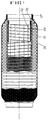
- Fig. 1 is a sectional view, with portions broken away for clarity, of a fundamental structure of this invention.
- an isolating member 60 is positioned between a bellows member 10 and an interlock member 20.
- Fig. 2 shows another embodiment of this invention.
- the isolating member 60 is positioned between the interlock member 20 and the bellows member 10
- an outer isolating member 70 is also positioned between the bellows member 10 and a braid member 30.
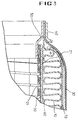
- Fig. 3 illustrates an enlarged view of essential parts of Fig. 2.
- the bellows member 10 is formed in a cylindrically corrugated shape.
- the cylindrically corrugated bellows member 10 is recovered in its original shape when the external force is removed after absorbing the axial and the bending displacements.
- the interlock member 20 is located with a prescribed gap from the bellows member 10.
- the interlock member 20 is spirally wound to form spiral grooves 21, thereby absorbing the deflections due to the various motions of the exhaust pipe.
- the bellows member 10 is surrounded by the braid member 30 formed by weaving or knitting a small-diameter metal wire.
- the bellows member 10 and the braid member 30 are pressed by caps 40 at their both end parts.
- the bellows member 10 and the interlock member 20 are connected together by fixing two ring-shaped intermediate members 50 at both ends thereof respectively.
- the intermediate members 50 are bent at the middle part to form a two-stepped shape.
- the ends of the bellows member 10, the braid member 30, and the cap 40 are aligned together as shown in Fig. 3 and are fixably engaged altogether by clamping, spot-welding, or the like.
- the interlock member 20 is aligned outside the intermediate member 50 and fixably engaged together by spot-welding at several places. Therefore, the bellows member 10 and the interlock member 20 can be connected by the intermediate members 50.
- the isolating member 60 is positioned between the interlock member 20 and the bellows member 10 so as to prevent uncomfortable noise, abrasion and damage of the bellows member 10.
- the isolating member 60 between the interlock member 20 and the bellows member 10 is positioned to block the interlock member 20 and the bellows member 10 from directly contacting each other and to provide elasticity in circumferential direction and axial direction.
- the isolating member 60 is made of elastic material having elasticity in vertical direction, circumferential direction and axial direction, and having good durability and heat-resistance. For this, it is preferable that cylindrical meshes formed by weaving or knitting a small-diameter wires are used.
- the small wire has a diameter of 0.1-0.3mm and is a stainless steel wire having good heat-resistance.
- Figs. 5 and 6 show weaved states of the isolating member 60 respectively.
- Fig. 5 illustrates the weaved state that the stainless steel wires are weaved in a loop shape with one another.
- Fig. 6 illustrates the weaved state that the stainless steel wires are weaved in a lattice shape.
- other proper netting shape having the same function and use may be used.
- the isolating member 60 approximately has the same length as the interlock member 20, and is positioned on the interlock member 20 which is located on the end of the intermediate member 50.
- the isolating member 60 and the interlock member 20 are fixed onto the end of the intermediate member 50 by spot-welding at several places.
- the isolating member 60 may be used in order for the isolating member 60 not to be moved.
- the isolating member 60 may be positioned freely without fixing by the fixing means.
- the outer isolating member 70 which is made of material having the same shape and quality as the isolating member 60 may be also positioned between the bellows member 10 and the braid member 30.
- the outer isolating member 70 is provided to prevent the unpleasant noise, the abrasion and damage of the bellows member 10 occurred by directly contacting the bellows member 10 with the braid member 30, and to protect the damage of the bellows member 10 by hit of stones or others from the road during running.
- the outer isolating member 70 is fixed onto the bellows member 10 by spot-welding in the same way as the isolating member 60. However, the outer isolating member 70 may be positioned freely without any fixing means.
- the isolating member 60 blocks the bellows member 10 and the interlock member 20 from directly contacting each other, and the outer isolating member 70 blocks the bellows member 10 and the braid member 30 from contacting and protects the outside of the bellows member 10. Therefore, the isolating members 60 and 70 can prevent effectively the abrasion and damage of the bellows member 10 caused by frequently contacting the bellows member 10 with the interlock member 20 and the braid member 30, thus preventing positively the leakage of exhaust gas. Furthermore, the isolating members 60 and 70 are made of axial flexible material, thus absorbing the axial displacement and protecting the bellows member 10 from damage and abrasion.
Landscapes
- Engineering & Computer Science (AREA)
- General Engineering & Computer Science (AREA)
- Mechanical Engineering (AREA)
- Chemical & Material Sciences (AREA)
- Combustion & Propulsion (AREA)
- Exhaust Silencers (AREA)
Applications Claiming Priority (2)
| Application Number | Priority Date | Filing Date | Title |
|---|---|---|---|
| KR1019980029120A KR100294471B1 (ko) | 1998-07-20 | 1998-07-20 | 자동차배기관용플랙시블튜브 |
| KR9829120 | 1998-07-20 |
Publications (1)
| Publication Number | Publication Date |
|---|---|
| EP0974741A1 true EP0974741A1 (fr) | 2000-01-26 |
Family
ID=19544620
Family Applications (1)
| Application Number | Title | Priority Date | Filing Date |
|---|---|---|---|
| EP99113596A Withdrawn EP0974741A1 (fr) | 1998-07-20 | 1999-07-08 | Tube flexible pour tuyau de gaz d'échappement pour vehicules à moteur |
Country Status (2)
| Country | Link |
|---|---|
| EP (1) | EP0974741A1 (fr) |
| KR (1) | KR100294471B1 (fr) |
Cited By (18)
| Publication number | Priority date | Publication date | Assignee | Title |
|---|---|---|---|---|
| WO2000070257A1 (fr) * | 1999-05-12 | 2000-11-23 | Contitech Schlauch Gmbh | Flexible souple, en particulier flexible haute pression subissant une deformation sous l'effet de la pression |
| EP1467072A1 (fr) * | 2003-04-07 | 2004-10-13 | IWKA Balg- und Kompensatoren Technologie GmbH | Elément de conduite flexible |
| FR2857050A1 (fr) * | 2003-07-04 | 2005-01-07 | Hutchinson | Perfectionnement a un flexible de decouplage pour ligne d'echappement d'un vehicule a moteur |
| FR2859266A1 (fr) * | 2003-09-03 | 2005-03-04 | Tubest Sa | Tubulure a isolation thermique et sonore renforcee |
| WO2005024197A1 (fr) * | 2003-08-05 | 2005-03-17 | Witzenmann Gmbh | Element de conduite flexible |
| WO2006029201A1 (fr) * | 2004-09-08 | 2006-03-16 | Donaldson Company, Inc. | Construction d'un composant d'un systeme d'echappement d'un moteur |
| EP1681503A1 (fr) * | 2005-01-14 | 2006-07-19 | Tubest Flexible Solutions | Tubulaire rigide à isolation thermique et sonore renforcée |
| DE202007013515U1 (de) * | 2007-09-27 | 2009-02-19 | Witzenmann Gmbh | Dämpfungsanordnung |
| DE202008008290U1 (de) * | 2008-06-20 | 2009-10-29 | Witzenmann Gmbh | Flexibles Leitungselement für die Abgasleitung eines Brennkraftmotors |
| US7779624B2 (en) | 2004-09-08 | 2010-08-24 | Donaldson Company, Inc. | Joint for an engine exhaust system component |
| EP2302275A1 (fr) * | 2009-09-29 | 2011-03-30 | Tru-Flex Metal Hose Corp. | Conduit de système d'échappement avec isolation thermique/sonore |
| US20110073209A1 (en) * | 2009-09-30 | 2011-03-31 | Honda Motor Co., Ltd. | Flexible vibration absorbing tube |
| WO2011134633A1 (fr) * | 2010-04-29 | 2011-11-03 | Boa Balg- Und Kompensatoren-Technologie Gmbh | Élément de conduite souple |
| EP2450544A1 (fr) * | 2010-11-09 | 2012-05-09 | Tru-Flex Metal Hose, LLC | Élément amélioré de connexion d'échappement compressible |
| EP2450546A1 (fr) * | 2010-11-09 | 2012-05-09 | Tru-Flex Metal Hose, LLC | Ensemble formant soufflet d'échappement contrôlé par la fréquence |
| EP2450545A1 (fr) * | 2010-11-09 | 2012-05-09 | Tru-Flex Metal Hose, LLC | Élément de connexion d'échappement doté d'un manchon tressé préformé |
| DE102012216097A1 (de) * | 2012-09-12 | 2014-03-13 | Witzenmann Gmbh | Entkoppelelement |
| WO2016001731A1 (fr) * | 2014-07-02 | 2016-01-07 | American Boa Inc. | Manchon de chemise dynamique pour couplage souple |
Families Citing this family (5)
| Publication number | Priority date | Publication date | Assignee | Title |
|---|---|---|---|---|
| KR100393395B1 (ko) * | 2001-02-07 | 2003-07-31 | 주식회사 에스제이엠 | 자동차용 플랙시블 튜브 |
| KR100492081B1 (ko) * | 2002-01-07 | 2005-06-02 | 주식회사 에스제이엠 | 자동차 배기관용 플렉시블 튜브 |
| KR100508167B1 (ko) * | 2002-10-09 | 2005-08-17 | 현대자동차주식회사 | 듀얼 배기관용 플렉시블 파이프의 듀얼 플랜지의 구조 |
| KR20050044029A (ko) * | 2003-11-07 | 2005-05-12 | 현대자동차주식회사 | 내구력 개선을 위한 벨로우즈 구조 |
| KR101570921B1 (ko) | 2014-01-22 | 2015-11-20 | 주식회사 에스제이엠 | 자동차 배기관용 플렉시블 튜브 |
Citations (5)
| Publication number | Priority date | Publication date | Assignee | Title |
|---|---|---|---|---|
| US3420553A (en) * | 1966-02-09 | 1969-01-07 | Calumet & Hecla | Apparatus for absorbing sound and vibration in a piping system |
| EP0282689A2 (fr) * | 1987-03-14 | 1988-09-21 | Witzenmann GmbH Metallschlauch-Fabrik Pforzheim | Elément de conduite flexible pour conduites de gas d'échappement de moteurs à combustion interne |
| EP0493680A1 (fr) * | 1990-12-31 | 1992-07-08 | Witzenmann GmbH Metallschlauch-Fabrik Pforzheim | Elément de conduite flexible pour tuyaux d'échappement de moteurs à combustion interne pour véhicules |
| US5437479A (en) * | 1992-10-06 | 1995-08-01 | Feodor Burgmann Dichtungswerke Gmbh & Co. | Flexible connection arrangement for the two pipe portions particularly for motor vehicle exhausts |
| DE4417407C1 (de) * | 1994-05-18 | 1995-11-30 | Burgmann Dichtungswerk Feodor | Flexible Verbindungsanordnung für zwei Rohrteile, insbesondere bei Abgasanlagen von Kraftfahrzeugen |
Family Cites Families (2)
| Publication number | Priority date | Publication date | Assignee | Title |
|---|---|---|---|---|
| JPH0347421A (ja) * | 1989-07-14 | 1991-02-28 | Tanaka Pipe:Kk | 排気マフラのインナパイプ製作方法 |
| KR960006036Y1 (ko) * | 1994-12-28 | 1996-07-20 | 성진기공 주식회사 | 배기관용 연결구 |
-
1998
- 1998-07-20 KR KR1019980029120A patent/KR100294471B1/ko not_active Expired - Fee Related
-
1999
- 1999-07-08 EP EP99113596A patent/EP0974741A1/fr not_active Withdrawn
Patent Citations (5)
| Publication number | Priority date | Publication date | Assignee | Title |
|---|---|---|---|---|
| US3420553A (en) * | 1966-02-09 | 1969-01-07 | Calumet & Hecla | Apparatus for absorbing sound and vibration in a piping system |
| EP0282689A2 (fr) * | 1987-03-14 | 1988-09-21 | Witzenmann GmbH Metallschlauch-Fabrik Pforzheim | Elément de conduite flexible pour conduites de gas d'échappement de moteurs à combustion interne |
| EP0493680A1 (fr) * | 1990-12-31 | 1992-07-08 | Witzenmann GmbH Metallschlauch-Fabrik Pforzheim | Elément de conduite flexible pour tuyaux d'échappement de moteurs à combustion interne pour véhicules |
| US5437479A (en) * | 1992-10-06 | 1995-08-01 | Feodor Burgmann Dichtungswerke Gmbh & Co. | Flexible connection arrangement for the two pipe portions particularly for motor vehicle exhausts |
| DE4417407C1 (de) * | 1994-05-18 | 1995-11-30 | Burgmann Dichtungswerk Feodor | Flexible Verbindungsanordnung für zwei Rohrteile, insbesondere bei Abgasanlagen von Kraftfahrzeugen |
Cited By (29)
| Publication number | Priority date | Publication date | Assignee | Title |
|---|---|---|---|---|
| US6761188B1 (en) | 1999-05-12 | 2004-07-13 | Continental Aktiengesellschaft | Flexible hose line, in particular, high pressure hose line which is subjected to a pressurized forming process |
| WO2000070257A1 (fr) * | 1999-05-12 | 2000-11-23 | Contitech Schlauch Gmbh | Flexible souple, en particulier flexible haute pression subissant une deformation sous l'effet de la pression |
| EP1467072A1 (fr) * | 2003-04-07 | 2004-10-13 | IWKA Balg- und Kompensatoren Technologie GmbH | Elément de conduite flexible |
| FR2857050A1 (fr) * | 2003-07-04 | 2005-01-07 | Hutchinson | Perfectionnement a un flexible de decouplage pour ligne d'echappement d'un vehicule a moteur |
| EP1496213A1 (fr) * | 2003-07-04 | 2005-01-12 | Hutchinson | Perfectionnements à un flexible de découplage pour ligne d'échappement d'un véhicule à moteur |
| WO2005024197A1 (fr) * | 2003-08-05 | 2005-03-17 | Witzenmann Gmbh | Element de conduite flexible |
| FR2859266A1 (fr) * | 2003-09-03 | 2005-03-04 | Tubest Sa | Tubulure a isolation thermique et sonore renforcee |
| US7779624B2 (en) | 2004-09-08 | 2010-08-24 | Donaldson Company, Inc. | Joint for an engine exhaust system component |
| WO2006029201A1 (fr) * | 2004-09-08 | 2006-03-16 | Donaldson Company, Inc. | Construction d'un composant d'un systeme d'echappement d'un moteur |
| EP1681503A1 (fr) * | 2005-01-14 | 2006-07-19 | Tubest Flexible Solutions | Tubulaire rigide à isolation thermique et sonore renforcée |
| DE202007013515U1 (de) * | 2007-09-27 | 2009-02-19 | Witzenmann Gmbh | Dämpfungsanordnung |
| DE202008008290U1 (de) * | 2008-06-20 | 2009-10-29 | Witzenmann Gmbh | Flexibles Leitungselement für die Abgasleitung eines Brennkraftmotors |
| EP2302275A1 (fr) * | 2009-09-29 | 2011-03-30 | Tru-Flex Metal Hose Corp. | Conduit de système d'échappement avec isolation thermique/sonore |
| US20160186897A1 (en) * | 2009-09-29 | 2016-06-30 | Tru-Flex, Llc | Exhaust system conduit with thermal/noise insulation |
| US9261216B2 (en) | 2009-09-29 | 2016-02-16 | Tru-Flex, Llc | Exhaust system conduit with thermal/noise insulation |
| US20110073209A1 (en) * | 2009-09-30 | 2011-03-31 | Honda Motor Co., Ltd. | Flexible vibration absorbing tube |
| US8844579B2 (en) * | 2009-09-30 | 2014-09-30 | Honda Motor Co., Ltd. | Flexible vibration absorbing tube |
| WO2011134633A1 (fr) * | 2010-04-29 | 2011-11-03 | Boa Balg- Und Kompensatoren-Technologie Gmbh | Élément de conduite souple |
| US8382165B2 (en) | 2010-11-09 | 2013-02-26 | Tru-Flex Metal Hose, Llc | Exhaust connection member with preformed braided cover |
| EP2450545A1 (fr) * | 2010-11-09 | 2012-05-09 | Tru-Flex Metal Hose, LLC | Élément de connexion d'échappement doté d'un manchon tressé préformé |
| US9009972B2 (en) | 2010-11-09 | 2015-04-21 | Tru-Flex, Llc | Method for manufacturing exhaust connection member with preformed braided cover |
| EP2450546A1 (fr) * | 2010-11-09 | 2012-05-09 | Tru-Flex Metal Hose, LLC | Ensemble formant soufflet d'échappement contrôlé par la fréquence |
| EP2450544A1 (fr) * | 2010-11-09 | 2012-05-09 | Tru-Flex Metal Hose, LLC | Élément amélioré de connexion d'échappement compressible |
| US10066537B2 (en) | 2010-11-09 | 2018-09-04 | Tru-Flex, Llc | Exhaust connection member with braided cover and method of making the same |
| DE102012216097A1 (de) * | 2012-09-12 | 2014-03-13 | Witzenmann Gmbh | Entkoppelelement |
| DE102012216097B4 (de) | 2012-09-12 | 2024-11-28 | Witzenmann Gmbh | Entkoppelelement |
| WO2016001731A1 (fr) * | 2014-07-02 | 2016-01-07 | American Boa Inc. | Manchon de chemise dynamique pour couplage souple |
| US20160003388A1 (en) * | 2014-07-02 | 2016-01-07 | American Boa, Inc. | Dynamic liner sleeve for flexible coupling |
| US9970578B2 (en) * | 2014-07-02 | 2018-05-15 | American Boa, Inc. | Dynamic liner sleeve for flexible coupling |
Also Published As
| Publication number | Publication date |
|---|---|
| KR100294471B1 (ko) | 2001-09-17 |
| KR20000008987A (ko) | 2000-02-15 |
Similar Documents
| Publication | Publication Date | Title |
|---|---|---|
| EP0974741A1 (fr) | Tube flexible pour tuyau de gaz d'échappement pour vehicules à moteur | |
| JP6078033B2 (ja) | 自動車の排気管用可撓性導管 | |
| CA2517688C (fr) | Tube flexible pour tuyau d'echappement d'automobile | |
| KR100353123B1 (ko) | 자동차 배기관용 연결구 | |
| KR100281630B1 (ko) | 자동차 배기관용 디커플러 | |
| EP1326043B1 (fr) | Elément de conduite flexible | |
| US6220023B1 (en) | Line element with damping, particularly for exhaust pipes of internal combustion engines in motor vehicles | |
| US20140261842A1 (en) | Flexible tube for exhaust pipe of automobiles | |
| CA2479448C (fr) | Tube flexible pour tuyau d'echappement d'automobile | |
| US6047993A (en) | Arrangement for connection pipe pieces and method of making same | |
| JP3853903B2 (ja) | 自動車排気系用フレキシブルチューブ | |
| KR200184089Y1 (ko) | 자동차 배기관용 플렉시블 연결구 | |
| KR100492081B1 (ko) | 자동차 배기관용 플렉시블 튜브 | |
| CN208918660U (zh) | 柔性导管元件 | |
| KR100393395B1 (ko) | 자동차용 플랙시블 튜브 | |
| KR100353122B1 (ko) | 자동차 배기관용 연결구 | |
| JP2750456B2 (ja) | 金属製蛇腹管 | |
| JPH1122457A (ja) | 自動車排気系用フレキシブルチューブおよびそれに使用するコイルバネの固定方法 | |
| KR200150355Y1 (ko) | 자동차 배기관용 디커플러 | |
| JPH08303664A (ja) | 球面継手 | |
| KR200240736Y1 (ko) | 자동차용 플렉시블 커플링 | |
| KR200243764Y1 (ko) | 자동차 배기관용 플랙시블 커플링 | |
| KR20030094687A (ko) | 자동차 배기관용 플렉시블 튜브 | |
| KR100361078B1 (ko) | 자동차 배기관용 디커플러 | |
| KR200313051Y1 (ko) | 엔진 배기관용 디커플러 |
Legal Events
| Date | Code | Title | Description |
|---|---|---|---|
| PUAI | Public reference made under article 153(3) epc to a published international application that has entered the european phase |
Free format text: ORIGINAL CODE: 0009012 |
|
| AK | Designated contracting states |
Kind code of ref document: A1 Designated state(s): AT BE CH CY DE DK ES FI FR GB GR IE IT LI LU MC NL PT SE |
|
| AX | Request for extension of the european patent |
Free format text: AL;LT;LV;MK;RO;SI |
|
| 17P | Request for examination filed |
Effective date: 20000309 |
|
| 17Q | First examination report despatched |
Effective date: 20000425 |
|
| AKX | Designation fees paid | ||
| STAA | Information on the status of an ep patent application or granted ep patent |
Free format text: STATUS: THE APPLICATION IS DEEMED TO BE WITHDRAWN |
|
| 18D | Application deemed to be withdrawn |
Effective date: 20000906 |