EP0974772A1 - Mécanisme d'entraínement excentrique à course réglable - Google Patents
Mécanisme d'entraínement excentrique à course réglable Download PDFInfo
- Publication number
- EP0974772A1 EP0974772A1 EP99113210A EP99113210A EP0974772A1 EP 0974772 A1 EP0974772 A1 EP 0974772A1 EP 99113210 A EP99113210 A EP 99113210A EP 99113210 A EP99113210 A EP 99113210A EP 0974772 A1 EP0974772 A1 EP 0974772A1
- Authority
- EP
- European Patent Office
- Prior art keywords
- eccentric
- eccentric shaft
- shaft
- bushing
- centrifugal force
- Prior art date
- Legal status (The legal status is an assumption and is not a legal conclusion. Google has not performed a legal analysis and makes no representation as to the accuracy of the status listed.)
- Granted
Links
- 238000013459 approach Methods 0.000 claims description 21
- 230000002093 peripheral effect Effects 0.000 claims description 6
- 230000001154 acute effect Effects 0.000 claims description 2
- 230000000694 effects Effects 0.000 claims description 2
- 238000003466 welding Methods 0.000 description 4
- 238000004519 manufacturing process Methods 0.000 description 2
- 239000000463 material Substances 0.000 description 2
- 238000000034 method Methods 0.000 description 2
- 239000004033 plastic Substances 0.000 description 2
- 238000002372 labelling Methods 0.000 description 1
- 229920001169 thermoplastic Polymers 0.000 description 1
- 239000004416 thermosoftening plastic Substances 0.000 description 1
Images


Classifications
-
- F—MECHANICAL ENGINEERING; LIGHTING; HEATING; WEAPONS; BLASTING
- F16—ENGINEERING ELEMENTS AND UNITS; GENERAL MEASURES FOR PRODUCING AND MAINTAINING EFFECTIVE FUNCTIONING OF MACHINES OR INSTALLATIONS; THERMAL INSULATION IN GENERAL
- F16H—GEARING
- F16H21/00—Gearings comprising primarily only links or levers, with or without slides
- F16H21/10—Gearings comprising primarily only links or levers, with or without slides all movement being in, or parallel to, a single plane
- F16H21/16—Gearings comprising primarily only links or levers, with or without slides all movement being in, or parallel to, a single plane for interconverting rotary motion and reciprocating motion
- F16H21/18—Crank gearings; Eccentric gearings
- F16H21/20—Crank gearings; Eccentric gearings with adjustment of throw
-
- Y—GENERAL TAGGING OF NEW TECHNOLOGICAL DEVELOPMENTS; GENERAL TAGGING OF CROSS-SECTIONAL TECHNOLOGIES SPANNING OVER SEVERAL SECTIONS OF THE IPC; TECHNICAL SUBJECTS COVERED BY FORMER USPC CROSS-REFERENCE ART COLLECTIONS [XRACs] AND DIGESTS
- Y10—TECHNICAL SUBJECTS COVERED BY FORMER USPC
- Y10T—TECHNICAL SUBJECTS COVERED BY FORMER US CLASSIFICATION
- Y10T74/00—Machine element or mechanism
- Y10T74/21—Elements
- Y10T74/211—Eccentric
- Y10T74/2114—Adjustable
-
- Y—GENERAL TAGGING OF NEW TECHNOLOGICAL DEVELOPMENTS; GENERAL TAGGING OF CROSS-SECTIONAL TECHNOLOGIES SPANNING OVER SEVERAL SECTIONS OF THE IPC; TECHNICAL SUBJECTS COVERED BY FORMER USPC CROSS-REFERENCE ART COLLECTIONS [XRACs] AND DIGESTS
- Y10—TECHNICAL SUBJECTS COVERED BY FORMER USPC
- Y10T—TECHNICAL SUBJECTS COVERED BY FORMER US CLASSIFICATION
- Y10T74/00—Machine element or mechanism
- Y10T74/21—Elements
- Y10T74/211—Eccentric
- Y10T74/2116—Eccentric having anti-friction means, e.g., roller bearing, lubrication, etc.
Definitions
- the invention relates to an eccentric drive with an eccentric shaft, the Cylindrical eccentric with eccentric bushing when rotating the eccentric shaft describes a circular movement that over Connecting rods, tappets etc. can be converted into a reciprocating movement is.
- the known eccentric drives, crank drives or cam drives are used to do this, a rotational movement in a translatory back and forth movement convert, or vice versa.
- Such drives usually have a fixed stroke, which corresponds to the eccentricity of the eccentric the eccentric shaft / camshaft or the amount of crank crank corresponds to the crankshaft.
- the invention has for its object to an eccentric drive create in which it is ensured that the eccentricity or Conrod stroke position changeable and after switching off the eccentric drive is always the same as before the eccentric drive was switched on, without complex measuring, control and regulation techniques to have to use.
- the eccentric drive according to the invention is cylindrical trained eccentric of the eccentric shaft in the cylinder bore Eccentric bush is rotatably mounted such that when the Eccentric drive to bring about the concentricity, the eccentricities of the eccentric of the eccentric shaft and cylinder bore of the Pick up the eccentric bushing while the eccentric shaft rotates under the influence of centrifugal force on at least one actuator automatically Centrifugal controlled rotation between the eccentric shaft and the eccentric bush against each other while removing the concentricity and the eccentricity at the output of the eccentric drive is effective the eccentric system is from a first position (rest position or approach position) automatically into a second position (Working position or operating position) can be rotated at which the eccentric system a predetermined eccentricity and thus on the output has a predetermined connecting rod stroke, the z. B. for the tool carrier a machine can be used.
- the stroke of the eccentric drive is automatically adjustable in this way or adjustable that the at least one with the eccentric drive co-rotating actuator moves under centrifugal force and attacks both on the eccentric shaft and on the eccentric sleeve and these two components against each other by a certain angle twisted and thus automatically changes the eccentricities or sets, after switching off the eccentric drive after the centrifugal force has ceased to act on the actuator, the eccentricity change by at least one return spring undone.
- the connecting rod stroke position is always exactly the same as before switching on the eccentric drive.
- both the eccentric shaft in its peripheral area as well as the eccentric bush in their peripheral area at least one axially extending Have approach, the centrifugal force at least one actuator is spread between the approaches that Approaches against the force of the at least one return spring apart and eccentric shaft and eccentric bushing against each other twisted.
- the automatically centrifugal actuator can z. B. a mass body for example, in the form of a ball in the annulus between the eccentric shaft and the approaches of the eccentric shaft and Eccentric bushing is freely movable.
- the automatically centrifugal controlled Actuator can also, for. B. be at least one lever arm with its one end on an attachment of the eccentric shaft or eccentric bushing is articulated and with its other end under the influence of centrifugal force swings out at the adjacent attachment of the eccentric bush or eccentric shaft that pushes the lugs apart and eccentric shaft and eccentric bushing against the force of the return spring twisted against each other.
- Fig. 1 shows how the eccentric drive according to the invention with its central eccentric shaft 10, the z. B. is driven by an electric motor, is rotatably supported via bearings 12 and 13 in a housing 14, 15.
- the eccentric shaft 10 carries a cylindrical eccentric 16, the eccentricity of which is indicated by x.
- the cylindrical eccentric 16 of the eccentric shaft 10 is rotatably mounted in a cylinder bore 17 of an eccentric bushing 18.
- the eccentric bushing 18 is supported by connecting rod bearings 19 in the end region of a connecting rod 20, which is capable of rotating the eccentric shaft 10 in a reciprocating stroke movement, for. B. convert in a work machine.
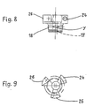
- the eccentric shaft 10 in its peripheral region z. B. three lugs 21, 22, 23 arranged around the circumference on that extend approximately axially.
- the eccentric bushing 18 also has in its peripheral area three arranged around the circumference also axially extending lugs 24, 25, 26, wherein e.g. B. the approach 21 of the eccentric shaft 10 between the adjacent Approaches 24, 26 of the eccentric bush 18 comes to rest.
- mass bodies three freely movable balls 27, 28, 29 arranged at Rotation of the eccentric drive under centrifugal force and act as actuators as follows:
- Fig. 2 shows the eccentric drive in the rest position, i. H. before the Switch on the drive motor.
- Eccentric 16 of the eccentric shaft 10 in the cylinder bore 17 of the eccentric bush 18 so that the eccentricities x and y of Eccentric of the eccentric shaft and cylinder bore of the eccentric bush to bring about the exact concentricity of the system straight cancel.
- the balls 27, 28, 29 are subjected to centrifugal force on the periphery hurled and they press radially outwards against themselves Working surfaces or wedge surfaces narrowing at an acute angle the approaches of the eccentric shaft and eccentric bush. So you see in Figures 2 and 3, such as. B.
- the invention is not only for eccentric drives, but also for crank drives, Cam drives etc. applicable, their stroke or eccentricity should be automatically adjustable for certain areas of application.
Landscapes
- Engineering & Computer Science (AREA)
- General Engineering & Computer Science (AREA)
- Mechanical Engineering (AREA)
- Transmission Devices (AREA)
Applications Claiming Priority (2)
| Application Number | Priority Date | Filing Date | Title |
|---|---|---|---|
| DE19832511A DE19832511A1 (de) | 1998-07-20 | 1998-07-20 | Exzentertrieb mit verstellbarem Hub |
| DE19832511 | 1998-07-20 |
Publications (2)
| Publication Number | Publication Date |
|---|---|
| EP0974772A1 true EP0974772A1 (fr) | 2000-01-26 |
| EP0974772B1 EP0974772B1 (fr) | 2003-03-19 |
Family
ID=7874629
Family Applications (1)
| Application Number | Title | Priority Date | Filing Date |
|---|---|---|---|
| EP99113210A Expired - Lifetime EP0974772B1 (fr) | 1998-07-20 | 1999-07-08 | Mécanisme d'entraínement excentrique à course réglable |
Country Status (4)
| Country | Link |
|---|---|
| US (1) | US6250178B1 (fr) |
| EP (1) | EP0974772B1 (fr) |
| DE (2) | DE19832511A1 (fr) |
| ES (1) | ES2193629T3 (fr) |
Families Citing this family (1)
| Publication number | Priority date | Publication date | Assignee | Title |
|---|---|---|---|---|
| DE112017001066T5 (de) | 2016-02-29 | 2018-11-08 | Fenner U.S., Inc. | Förderbandverbinder und verfahren zum bilden eines bandes |
Citations (4)
| Publication number | Priority date | Publication date | Assignee | Title |
|---|---|---|---|---|
| US3180178A (en) * | 1962-09-10 | 1965-04-27 | Ingersoll Rand Co | Variable stroke reciprocating machine |
| US3554846A (en) * | 1968-03-21 | 1971-01-12 | Fmc Corp | Friction welding apparatus |
| DE3441213C1 (de) * | 1984-11-10 | 1986-02-20 | Dornier System Gmbh, 7990 Friedrichshafen | Kurbelgetriebe |
| DE4226361A1 (de) * | 1992-08-10 | 1994-04-07 | Alex Zimmer | Brennkraftmaschine |
-
1998
- 1998-07-20 DE DE19832511A patent/DE19832511A1/de not_active Withdrawn
-
1999
- 1999-07-08 ES ES99113210T patent/ES2193629T3/es not_active Expired - Lifetime
- 1999-07-08 EP EP99113210A patent/EP0974772B1/fr not_active Expired - Lifetime
- 1999-07-08 DE DE59904596T patent/DE59904596D1/de not_active Expired - Lifetime
- 1999-07-19 US US09/356,455 patent/US6250178B1/en not_active Expired - Lifetime
Patent Citations (4)
| Publication number | Priority date | Publication date | Assignee | Title |
|---|---|---|---|---|
| US3180178A (en) * | 1962-09-10 | 1965-04-27 | Ingersoll Rand Co | Variable stroke reciprocating machine |
| US3554846A (en) * | 1968-03-21 | 1971-01-12 | Fmc Corp | Friction welding apparatus |
| DE3441213C1 (de) * | 1984-11-10 | 1986-02-20 | Dornier System Gmbh, 7990 Friedrichshafen | Kurbelgetriebe |
| DE4226361A1 (de) * | 1992-08-10 | 1994-04-07 | Alex Zimmer | Brennkraftmaschine |
Also Published As
| Publication number | Publication date |
|---|---|
| ES2193629T3 (es) | 2003-11-01 |
| DE59904596D1 (de) | 2003-04-24 |
| DE19832511A1 (de) | 2000-01-27 |
| US6250178B1 (en) | 2001-06-26 |
| EP0974772B1 (fr) | 2003-03-19 |
Similar Documents
| Publication | Publication Date | Title |
|---|---|---|
| DE869892C (de) | Spannvorrichtung | |
| DE69109338T2 (de) | Schneidscheibespindel, insbesondere für Teilmaschinen. | |
| DE3704412A1 (de) | Befestigungsvorrichtung fuer ein lenkgetriebegehaeuse | |
| DE3825944A1 (de) | Vorrichtung zum reibschweissen | |
| DE4001061A1 (de) | Spannring und vorrichtung zum zentrierten aufspannen eines rotationskoerpers auf einer aufspannwelle einer maschine | |
| CH647699A5 (de) | Antriebseinrichtung fuer biegeschlitten von stanz-biegeautomaten. | |
| DE2837801B1 (de) | Federbein fuer Trommelwaschmaschine | |
| DE3641295C2 (fr) | ||
| DE20014811U1 (de) | Invertmechanismus für eine Glasformmaschine | |
| EP0439684A1 (fr) | Presse à poinçonner | |
| DE2908422C2 (de) | Hon- oder Läppkopf | |
| EP0974772B1 (fr) | Mécanisme d'entraínement excentrique à course réglable | |
| DE102005034340B4 (de) | Planetengetriebe und Stellantrieb für Armaturen mit einem Planetengetriebe | |
| DE1901184A1 (de) | Vorrichtung zum dynamischen Auswuchten von Werkstuecken | |
| CH709379A1 (de) | Vorrichtung und Verfahren zur Herstellung einer Funktionswelle. | |
| DE2126059A1 (de) | Kurbelwelle mit Pleuellager fur Hub kolbenmaschinen | |
| DE20320068U1 (de) | Verbindung zweier Maschinenteile | |
| DE68903182T2 (de) | Loesbarer linearschrittmotor mit einem rueckzentrierten laeufer. | |
| DE3507328C2 (fr) | ||
| EP3541575B1 (fr) | Appareil de pose entraîné par volant d'inertie | |
| DE1897206U (de) | Schwingungsdaempfer. | |
| DE69019939T2 (de) | Presse und methode für materialbearbeitung. | |
| DE102012214058A1 (de) | Selbstsynchronisierende Gewindeschneideinrichtung zum starren oder synchronen Gewindeschneiden mit einstellbarer Spannunq und/oder Kompression | |
| DE69032677T2 (de) | Honwerkzeug und dieses honwerkzeug verwendendes hochgenaues feinstbearbeitungsverfahren | |
| DE3508186A1 (de) | Vorrichtung zum erzeugen einer bewegung |
Legal Events
| Date | Code | Title | Description |
|---|---|---|---|
| PUAI | Public reference made under article 153(3) epc to a published international application that has entered the european phase |
Free format text: ORIGINAL CODE: 0009012 |
|
| AK | Designated contracting states |
Kind code of ref document: A1 Designated state(s): CH DE ES FR GB IT LI |
|
| AX | Request for extension of the european patent |
Free format text: AL;LT;LV;MK;RO;SI |
|
| 17P | Request for examination filed |
Effective date: 20000519 |
|
| AKX | Designation fees paid |
Free format text: CH DE ES FR GB IT LI |
|
| 17Q | First examination report despatched |
Effective date: 20011218 |
|
| GRAH | Despatch of communication of intention to grant a patent |
Free format text: ORIGINAL CODE: EPIDOS IGRA |
|
| RAP1 | Party data changed (applicant data changed or rights of an application transferred) |
Owner name: BEHA INNOVATION GMBH |
|
| GRAH | Despatch of communication of intention to grant a patent |
Free format text: ORIGINAL CODE: EPIDOS IGRA |
|
| GRAA | (expected) grant |
Free format text: ORIGINAL CODE: 0009210 |
|
| AK | Designated contracting states |
Designated state(s): CH DE ES FR GB IT LI |
|
| REG | Reference to a national code |
Ref country code: GB Ref legal event code: FG4D Free format text: NOT ENGLISH |
|
| REG | Reference to a national code |
Ref country code: CH Ref legal event code: EP |
|
| REG | Reference to a national code |
Ref country code: CH Ref legal event code: NV Representative=s name: R. A. EGLI & CO. PATENTANWAELTE |
|
| REF | Corresponds to: |
Ref document number: 59904596 Country of ref document: DE Date of ref document: 20030424 Kind code of ref document: P |
|
| GBT | Gb: translation of ep patent filed (gb section 77(6)(a)/1977) | ||
| REG | Reference to a national code |
Ref country code: ES Ref legal event code: FG2A Ref document number: 2193629 Country of ref document: ES Kind code of ref document: T3 |
|
| ET | Fr: translation filed | ||
| PLBE | No opposition filed within time limit |
Free format text: ORIGINAL CODE: 0009261 |
|
| STAA | Information on the status of an ep patent application or granted ep patent |
Free format text: STATUS: NO OPPOSITION FILED WITHIN TIME LIMIT |
|
| 26N | No opposition filed |
Effective date: 20031222 |
|
| REG | Reference to a national code |
Ref country code: FR Ref legal event code: PLFP Year of fee payment: 18 |
|
| PGFP | Annual fee paid to national office [announced via postgrant information from national office to epo] |
Ref country code: ES Payment date: 20160722 Year of fee payment: 18 |
|
| REG | Reference to a national code |
Ref country code: FR Ref legal event code: PLFP Year of fee payment: 19 |
|
| PGFP | Annual fee paid to national office [announced via postgrant information from national office to epo] |
Ref country code: IT Payment date: 20170721 Year of fee payment: 19 Ref country code: GB Payment date: 20170724 Year of fee payment: 19 Ref country code: CH Payment date: 20170724 Year of fee payment: 19 Ref country code: FR Payment date: 20170720 Year of fee payment: 19 |
|
| PGFP | Annual fee paid to national office [announced via postgrant information from national office to epo] |
Ref country code: DE Payment date: 20180828 Year of fee payment: 20 |
|
| REG | Reference to a national code |
Ref country code: ES Ref legal event code: FD2A Effective date: 20181102 |
|
| PG25 | Lapsed in a contracting state [announced via postgrant information from national office to epo] |
Ref country code: ES Free format text: LAPSE BECAUSE OF NON-PAYMENT OF DUE FEES Effective date: 20170709 |
|
| REG | Reference to a national code |
Ref country code: CH Ref legal event code: PL |
|
| GBPC | Gb: european patent ceased through non-payment of renewal fee |
Effective date: 20180708 |
|
| PG25 | Lapsed in a contracting state [announced via postgrant information from national office to epo] |
Ref country code: LI Free format text: LAPSE BECAUSE OF NON-PAYMENT OF DUE FEES Effective date: 20180731 Ref country code: FR Free format text: LAPSE BECAUSE OF NON-PAYMENT OF DUE FEES Effective date: 20180731 Ref country code: CH Free format text: LAPSE BECAUSE OF NON-PAYMENT OF DUE FEES Effective date: 20180731 Ref country code: GB Free format text: LAPSE BECAUSE OF NON-PAYMENT OF DUE FEES Effective date: 20180708 |
|
| REG | Reference to a national code |
Ref country code: DE Ref legal event code: R071 Ref document number: 59904596 Country of ref document: DE |
|
| PG25 | Lapsed in a contracting state [announced via postgrant information from national office to epo] |
Ref country code: IT Free format text: LAPSE BECAUSE OF NON-PAYMENT OF DUE FEES Effective date: 20180708 |