EP0974789B1 - Procédé de fonctionnement d'une chambre de combustion de turbine à gaz à carburant liquide - Google Patents
Procédé de fonctionnement d'une chambre de combustion de turbine à gaz à carburant liquide Download PDFInfo
- Publication number
- EP0974789B1 EP0974789B1 EP19980810708 EP98810708A EP0974789B1 EP 0974789 B1 EP0974789 B1 EP 0974789B1 EP 19980810708 EP19980810708 EP 19980810708 EP 98810708 A EP98810708 A EP 98810708A EP 0974789 B1 EP0974789 B1 EP 0974789B1
- Authority
- EP
- European Patent Office
- Prior art keywords
- fuel
- burners
- burner
- water
- gas turbine
- Prior art date
- Legal status (The legal status is an assumption and is not a legal conclusion. Google has not performed a legal analysis and makes no representation as to the accuracy of the status listed.)
- Expired - Lifetime
Links
Images






Classifications
-
- F—MECHANICAL ENGINEERING; LIGHTING; HEATING; WEAPONS; BLASTING
- F02—COMBUSTION ENGINES; HOT-GAS OR COMBUSTION-PRODUCT ENGINE PLANTS
- F02C—GAS-TURBINE PLANTS; AIR INTAKES FOR JET-PROPULSION PLANTS; CONTROLLING FUEL SUPPLY IN AIR-BREATHING JET-PROPULSION PLANTS
- F02C9/00—Controlling gas-turbine plants; Controlling fuel supply in air- breathing jet-propulsion plants
- F02C9/26—Control of fuel supply
- F02C9/28—Regulating systems responsive to plant or ambient parameters, e.g. temperature, pressure, rotor speed
-
- F—MECHANICAL ENGINEERING; LIGHTING; HEATING; WEAPONS; BLASTING
- F02—COMBUSTION ENGINES; HOT-GAS OR COMBUSTION-PRODUCT ENGINE PLANTS
- F02C—GAS-TURBINE PLANTS; AIR INTAKES FOR JET-PROPULSION PLANTS; CONTROLLING FUEL SUPPLY IN AIR-BREATHING JET-PROPULSION PLANTS
- F02C3/00—Gas-turbine plants characterised by the use of combustion products as the working fluid
- F02C3/20—Gas-turbine plants characterised by the use of combustion products as the working fluid using a special fuel, oxidant, or dilution fluid to generate the combustion products
- F02C3/30—Adding water, steam or other fluids for influencing combustion, e.g. to obtain cleaner exhaust gases
-
- F—MECHANICAL ENGINEERING; LIGHTING; HEATING; WEAPONS; BLASTING
- F02—COMBUSTION ENGINES; HOT-GAS OR COMBUSTION-PRODUCT ENGINE PLANTS
- F02C—GAS-TURBINE PLANTS; AIR INTAKES FOR JET-PROPULSION PLANTS; CONTROLLING FUEL SUPPLY IN AIR-BREATHING JET-PROPULSION PLANTS
- F02C7/00—Features, components parts, details or accessories, not provided for in, or of interest apart form groups F02C1/00 - F02C6/00; Air intakes for jet-propulsion plants
- F02C7/22—Fuel supply systems
- F02C7/228—Dividing fuel between various burners
-
- F—MECHANICAL ENGINEERING; LIGHTING; HEATING; WEAPONS; BLASTING
- F02—COMBUSTION ENGINES; HOT-GAS OR COMBUSTION-PRODUCT ENGINE PLANTS
- F02C—GAS-TURBINE PLANTS; AIR INTAKES FOR JET-PROPULSION PLANTS; CONTROLLING FUEL SUPPLY IN AIR-BREATHING JET-PROPULSION PLANTS
- F02C7/00—Features, components parts, details or accessories, not provided for in, or of interest apart form groups F02C1/00 - F02C6/00; Air intakes for jet-propulsion plants
- F02C7/22—Fuel supply systems
- F02C7/232—Fuel valves; Draining valves or systems
-
- F—MECHANICAL ENGINEERING; LIGHTING; HEATING; WEAPONS; BLASTING
- F23—COMBUSTION APPARATUS; COMBUSTION PROCESSES
- F23R—GENERATING COMBUSTION PRODUCTS OF HIGH PRESSURE OR HIGH VELOCITY, e.g. GAS-TURBINE COMBUSTION CHAMBERS
- F23R3/00—Continuous combustion chambers using liquid or gaseous fuel
- F23R3/02—Continuous combustion chambers using liquid or gaseous fuel characterised by the air-flow or gas-flow configuration
- F23R3/26—Controlling the air flow
-
- F—MECHANICAL ENGINEERING; LIGHTING; HEATING; WEAPONS; BLASTING
- F23—COMBUSTION APPARATUS; COMBUSTION PROCESSES
- F23R—GENERATING COMBUSTION PRODUCTS OF HIGH PRESSURE OR HIGH VELOCITY, e.g. GAS-TURBINE COMBUSTION CHAMBERS
- F23R3/00—Continuous combustion chambers using liquid or gaseous fuel
- F23R3/28—Continuous combustion chambers using liquid or gaseous fuel characterised by the fuel supply
- F23R3/34—Feeding into different combustion zones
-
- F—MECHANICAL ENGINEERING; LIGHTING; HEATING; WEAPONS; BLASTING
- F23—COMBUSTION APPARATUS; COMBUSTION PROCESSES
- F23R—GENERATING COMBUSTION PRODUCTS OF HIGH PRESSURE OR HIGH VELOCITY, e.g. GAS-TURBINE COMBUSTION CHAMBERS
- F23R2900/00—Special features of, or arrangements for continuous combustion chambers; Combustion processes therefor
- F23R2900/00013—Reducing thermo-acoustic vibrations by active means
Definitions
- the present invention relates to the field of gas turbines. It concerns a procedure for operating a gas turbine in which a liquid fuel in a combustion chamber burned and the resulting hot combustion gases from the gas turbine are passed, and by which method the liquid fuel of the combustion chamber a plurality of controllable burners working in parallel are fed and into the combustion chamber is injected via fuel nozzles.
- Gas turbines are increasingly being equipped with multiple burners with lean premix technology.
- the fuel and combustion air become as uniform as possible premixed and only then fed to the flame. Will this be with a high excess of air carried out, this results in relatively low flame temperatures and thus a low one Formation of nitrogen oxides.
- the local Flame temperature can be lowered by injecting water. The effective ones Experience has shown that nitrogen oxide values are exponential to the amount of water.
- the majority of burners often become ring-shaped arranged in the form of an annular combustion chamber.
- gas turbine annular combustion chambers are known for example from EP 0597137 and EP 0597138.
- the liquid Fuels are the burners arranged in multiple rings via fuel feed rings fed where they are injected into the ring combustion chamber and burned. Likewise, the water supply to the burners is ensured via water rings, which next to the fuel feed rings are arranged.
- US-A-5 729 968 discloses a gas turbine combustor with water injection.
- the invention is therefore based on the object of specifying a method by which the formation of explosive mixtures and / or coking residues in the fuel lines inactive groups of burners is avoided.
- the object is achieved in a method of the type mentioned at the outset in that burner sections of the fuel lines from inactive groups to control valves be flooded with inert fuel additive, and that with inert fuel additive flooded near-fuel sections of fuel lines from inactive groups before Activation of these groups completely flooded by opening control valves with fuel be, the inert fuel additive via ventilation valves in leakage oil tanks is dissipated.
- the first step in which the fuel in the fuel line sections near the burner is replaced by inert fuel additive prevents the explosive fuel, which represents a potential safety risk, in the vicinity of the combustion chamber Fuel lines from inactive groups remain. Should inactive groups are switched on again, so the second step allows flooding of the near fuel Fuel lines with fuel so that the groups to be activated immediately after the Connect are fully available. The connection process is safe and through this procedure guaranteed uninterrupted.
- FIG. 1 gives a schematic representation of fuel system 10, water system 11 and Burner 12 of an embodiment.
- the burners 12 can be controlled individually in three Rings 70-72 divided by having three independent fuel feed rings 24-26 Fuel and are supplied by three also independent water rings 41-43 Water are supplied.
- the fuel supply of all burners via the fuel feed line 47 is via a fuel quick shutoff valve located directly behind a fuel pump 15 16 centrally regulated. After the fuel quick shutoff valve 16 The fuel line branches into three lines, the three fuel feed rings 24-26 supply and regulated individually by means of control valves 18-20.
- Fuel control valves 18-20 and the fuel supply rings 24-26 are also located each have a branch of the fuel lines in a leakage oil tank 13, which Branches are regulated by means of drainage valves 21-23 and emptied into the Allow fuel supply rings 24-26 contained fuel.
- the fuel feed rings 24-26 in turn have 13 leading to the leakage oil tank with ventilation valves 27-29 adjustable lines to drain the contained in the fuel feed rings 24-26 Allow water in the leakage oil tank 13.
- the fuel feed rings 24-26 are still divided into six sectors 61-66, each with fuel circuit sector outlets 30-32 be supplied.
- the water rings 41-43 are supplied via the water inlet 48 and with one of the Water pump 35 downstream water quick shutoff valve 36 centrally controlled.
- the Water line branches after the quick shut-off valve 36 in three lines with Control valves 38-40 are regulated independently and lead to the three water rings 41-43.
- the water rings 41-43 are each in six Sectors 61-66 are classified and the burners of these sectors are via water ring sector outlets 44-46 individually supplied.
- Such a sector 61-66 of a burner ring 70-72 is via a fuel sector inlet 50, which is one of the fuel supply ring sector outlets 30-32 via a water sector inlet 54 which is one of the water ring sector outlets 44-46 Water supplied.
- the fuel supply is regulated via a fuel sector valve 51, which Water supply through a water sector valve 53 before the lines branch and shut the burners in the sector.
- a connecting line 55 which connects to a Check valve 52 is regulated, and which connecting line 55 flooding the fuel supply rings Allowed 24-26 with water.
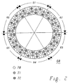
- Figure 2 shows a section through the annular combustion chamber with the burner rings 60 opposite the direction of gas flow.
- the three groups 70-72 of the 72 burners are by corresponding ones Hatching. Empty circles denote the 12 burners of the first burner ring 70, diagonally hatched circles the 24 burners of the second burner ring 71, and triangular grid filled Circles denote the 36 burners of the third burner ring 72. Furthermore the sector breakdown into six sectors 61-66 is given.
- Figure 3 again shows the section through the annular combustion chamber against the gas flow direction. Only the 12 burners of the first burner ring 70.1-70.12 are specified and labeled.
- Figure 4 shows the section through the annular combustion chamber against the gas flow direction. Just the 24 burners of the second burner ring 71.1-71.24 are indicated and labeled.
- Figure 5 shows the section through the annular combustion chamber against the gas flow direction. Just the 36 burners of the third burner ring 72.1-72.36 are indicated and labeled.
- FIG. 6 shows the number of active burners (ordinate) when the gas turbine is started up from standstill to idling as a function of the relative speed, expressed in% of the idling speed of 3000 min ⁇ 1 (abscissa).
- the gas turbine is first accelerated from the outside with a static starting device (SSD) to approx. 950 min -1 .
- the control valves 18 and 19 are opened by the first and second burner rings (24 and 25) with a filling mass flow of 7.8 and 16.0 kg / s already at 850 min -1 .
- the fuel quick shutoff valve 16 is opened and the fuel lines of the burner rings 24 and 25 are filled, the ventilation valves 27 and 28 being open.
- the sector valves 51 are closed during this filling. This separates the combustion chamber from the fuel and ensures safety during filling.
- the pressure behind the fuel pump 15 drops from approximately 100 bar to approximately 77 bar.
- the pressure in the fuel supply rings 24 and 25 is low because only air flows through the vent valves 27 and 28.
- pressure builds up, and as soon as the pressure in the lines exceeds 20 bar, the lines are full and the control valves of the first and second fuel feed ring begin to close.
- the gradient of this closing process is controlled in such a way that the mass flow via a PT1 is regulated to 0.5s for the first ring and to 1s for the second ring.
- the sector valves 51 of the sectors 62, 63, 65 and 66 are opened in the first 70 and second 71 fuel supply rings and fuel fills the lines between the sector valves 51 and the combustion chamber.
- the ventilation valves 27 and 28 are also closed.
- the pressure in the fuel supply rings 24 and 25 suddenly increases and the ignition starts.
- burners 70.3-70.6, 70.9-70.12, 71.5-71.12, 71.17-71.24 are ignited, namely the burners of the first burner ring 70 without the two opposite sectors 61 and 64.
- the ignition takes place at 950 min -1 and is very gentle and well controlled.
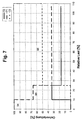
- FIG. 7 shows the relative distribution of the oil supply to the three burner rings 70-72 (ordinate) when starting up the gas turbine from idle to load operation as a function of Load (abscissa) relative to the defined full load (100%).
- FIG. 8 shows the fuel-air ratio ⁇ (ordinate) as a function of the load (abscissa) applied to the gas turbine in relation to the full load in the various driving ranges, the curves shown for a water to fuel ratio ⁇ of 0.9.
- the first phase 94 of 0-10% relative load only the second burner ring is active, which continuously receives more fuel, so that the fuel-air ratio ⁇ increases more and more.
- the first burner ring is then switched on again within 12s, the fuel being distributed homogeneously over all burners.
- the fuel supply ring 24 of the first burner ring 70 is initially still full of water, since it was flooded with water when it was idling at 2500 min ⁇ 1 .
- the control valve of the first fuel supply ring 18 is opened with the sector valves 51 closed and the ventilation valve 27 open.
- fuel is driven into the line system and the water in the line system is flushed through the ventilation valve 27 into the leakage oil tank 13.
- the ventilation valve 27 is closed and the sector valves 51 are opened.
- the first and the second are now Burner ring continuously controlled with fuel, as well as from the driving area 95 can be seen in FIG.
- the third burner ring 72 is switched on. This happens in the same way as the connection of the first burner ring 70 at 10% relative load, only when the third burner ring 72 is switched on is the switch-on time 30s.
- All 72 burners of the ring combustion chamber are then of 25% relative load in phase 96 in operation, and in turn the fuel supply becomes homogeneous on all burners continuously increased.
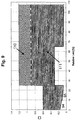
- FIG. 9 shows the water to fuel ratio ⁇ (ordinate) as a function of that on the gas turbine, which is dimensioned relative to full load applied load (abscissa) in the different driving areas.
- ⁇ defined as the ratio of mass of water to mass of fuel, hatched horizontally Area 111 of FIG. 9, the behavior of the gas turbine is absolutely safe, and without the development of smoke being visible.
- the specifically chosen value for ⁇ can accordingly nitrogen oxide emission regulations.
- the third burner ring proves to be advantageous 72 can only be switched off at 24.5% relative load.
- the third burner ring 72 is switched on and activated as can be seen from FIGS. 10 and 11.
- the third burner ring 72 receives when switched on less fuel than the second 71 and the first 70 ring (phase 121). Starting at approximately 38% This inhomogeneity of the fuel supply then becomes up to approx. 66% relative load (phase 122) continuously balanced, and in the fourth phase 123 you make the same Ratios as for the method using water. In this way, a pulsation the gas turbine can be avoided efficiently.
- phase 94 and 95 the unused ones Flush the burner with a minimal amount of water to avoid possible leakage oil to actually bring closed control valves into the combustion chamber in a controlled manner and thus prevent coking of individual burner lances.
Landscapes
- Engineering & Computer Science (AREA)
- Chemical & Material Sciences (AREA)
- Combustion & Propulsion (AREA)
- Mechanical Engineering (AREA)
- General Engineering & Computer Science (AREA)
- Feeding And Controlling Fuel (AREA)
Claims (2)
- Procédé de fonctionnement d'une turbine à gaz, dans laquelle un combustible liquide est brûlé dans une chambre de combustion et les gaz de combustion chauds produits sont conduits à travers la turbine à gaz, et dans lequel procédé le combustible liquide est acheminé à la chambre de combustion par le biais d'une pluralité de brûleurs (12) commandables, fonctionnant en parallèle, et est injecté dans la chambre de combustion par le biais d'injecteurs de combustible, et les brûleurs (12) sont divisés en au moins deux groupes (61-66, 70-72) de brûleurs (12), et ces groupes sont commandés individuellement en fonction de l'état de fonctionnement de la turbine à gaz, les brûleurs (12) étant alimentés au moyen de conduites de combustible (50) en combustible et au moyen de conduites supplémentaires de combustible (54) en supplément de combustible inerte, et à la fois les conduites de combustible (50) et les conduites supplémentaires de combustible (54) étant commandées individuellement par groupe, caractérisé en ce que des portions proches des brûleurs des conduites de combustible (50) de groupes inactifs sont remplies de supplément de combustible inerte jusqu'aux soupapes de commande (18-20), et en ce que les portions proches des brûleurs des conduites de combustible (50) de groupes inactifs remplies de supplément de combustible inerte sont complètement remplies de combustible avant l'activation de ces groupes par l'ouverture des soupapes de commande (18-20), le supplément de combustible inerte étant évacué dans le réservoir d'huile de fuite (13) par le biais de soupapes d'aération (27-29).
- Procédé selon la revendication 1, caractérisé en ce que l'on utilise de l'eau comme supplément de combustible inerte.
Priority Applications (2)
| Application Number | Priority Date | Filing Date | Title |
|---|---|---|---|
| EP19980810708 EP0974789B1 (fr) | 1998-07-22 | 1998-07-22 | Procédé de fonctionnement d'une chambre de combustion de turbine à gaz à carburant liquide |
| DE59811336T DE59811336D1 (de) | 1998-07-22 | 1998-07-22 | Verfahren zum Betrieb einer Gasturbinenbrennkammer mit flüssigem Brennstoff |
Applications Claiming Priority (1)
| Application Number | Priority Date | Filing Date | Title |
|---|---|---|---|
| EP19980810708 EP0974789B1 (fr) | 1998-07-22 | 1998-07-22 | Procédé de fonctionnement d'une chambre de combustion de turbine à gaz à carburant liquide |
Publications (2)
| Publication Number | Publication Date |
|---|---|
| EP0974789A1 EP0974789A1 (fr) | 2000-01-26 |
| EP0974789B1 true EP0974789B1 (fr) | 2004-05-06 |
Family
ID=8236208
Family Applications (1)
| Application Number | Title | Priority Date | Filing Date |
|---|---|---|---|
| EP19980810708 Expired - Lifetime EP0974789B1 (fr) | 1998-07-22 | 1998-07-22 | Procédé de fonctionnement d'une chambre de combustion de turbine à gaz à carburant liquide |
Country Status (2)
| Country | Link |
|---|---|
| EP (1) | EP0974789B1 (fr) |
| DE (1) | DE59811336D1 (fr) |
Cited By (3)
| Publication number | Priority date | Publication date | Assignee | Title |
|---|---|---|---|---|
| US8484979B2 (en) | 2007-03-15 | 2013-07-16 | Siemens Aktiengesellschaft | Burner fuel staging |
| RU2555427C1 (ru) * | 2014-07-31 | 2015-07-10 | Федеральное государственное унитарное предприятие "Научно-производственный центр газотурбостроения "Салют" (ФГУП "НПЦ газотурбостроения "Салют") | Способ заполнения топливных коллекторов камер сгорания газотурбинного двигателя |
| DE102006059532B4 (de) | 2006-02-20 | 2020-07-09 | Ansaldo Energia Ip Uk Limited | Verfahren zum Betreiben einer Gasturbinenanordnung mit sequentieller Verbrennung |
Families Citing this family (13)
| Publication number | Priority date | Publication date | Assignee | Title |
|---|---|---|---|---|
| US6983605B1 (en) | 2000-04-07 | 2006-01-10 | General Electric Company | Methods and apparatus for reducing gas turbine engine emissions |
| US6427447B1 (en) * | 2001-02-06 | 2002-08-06 | United Technologies Corporation | Bulkhead for dual fuel industrial and aeroengine gas turbines |
| US6962055B2 (en) | 2002-09-27 | 2005-11-08 | United Technologies Corporation | Multi-point staging strategy for low emission and stable combustion |
| EP1531305A1 (fr) * | 2003-11-12 | 2005-05-18 | United Technologies Corporation | Injecteur de carburant multi-point |
| JP4486549B2 (ja) * | 2005-06-06 | 2010-06-23 | 三菱重工業株式会社 | ガスタービンの燃焼器 |
| JP4418442B2 (ja) | 2006-03-30 | 2010-02-17 | 三菱重工業株式会社 | ガスタービンの燃焼器及び燃焼制御方法 |
| EP2024620B1 (fr) * | 2006-06-07 | 2015-07-29 | Alstom Technology Ltd | Procédé pour faire fonctionner une turbine à gaz et centrale combinée pour la mise en oeuvre du procédé |
| CH700796A1 (de) | 2009-04-01 | 2010-10-15 | Alstom Technology Ltd | Verfahren zum CO-emissionsarmen Betrieb einer Gasturbine mit sequentieller Verbrennung und Gasturbine mit verbessertem Teillast- Emissionsverhalten. |
| EP2423591B1 (fr) * | 2010-08-24 | 2018-10-31 | Ansaldo Energia IP UK Limited | Procédé de fonctionnement d'une chambre de combustion |
| JP5721447B2 (ja) * | 2011-01-17 | 2015-05-20 | 三菱日立パワーシステムズ株式会社 | ガスタービン燃焼器、これを備えたガスタービン、これを備えたガスタービンプラントおよびこの制御方法 |
| CA2829613C (fr) | 2012-10-22 | 2016-02-23 | Alstom Technology Ltd. | Procede pour faire fonctionner une turbine a gaz a combustion sequentielle et turbine a gaz pour executer ladite methode |
| EP4019844B1 (fr) * | 2020-12-24 | 2024-04-03 | Ansaldo Energia Switzerland AG | Moteur à turbine à gaz avec commande de carburant du premier et du second étage et procédé de commande d'un moteur à turbine à gaz |
| EP4426970A2 (fr) * | 2021-11-03 | 2024-09-11 | Power Systems Mfg., LLC | Injecteur pilote multitube ayant un ancrage de flamme pour un moteur à turbine à gaz |
Family Cites Families (6)
| Publication number | Priority date | Publication date | Assignee | Title |
|---|---|---|---|---|
| US4027473A (en) * | 1976-03-05 | 1977-06-07 | United Technologies Corporation | Fuel distribution valve |
| US4903478A (en) * | 1987-06-25 | 1990-02-27 | General Electric Company | Dual manifold fuel system |
| US5339635A (en) * | 1987-09-04 | 1994-08-23 | Hitachi, Ltd. | Gas turbine combustor of the completely premixed combustion type |
| US5289685A (en) * | 1992-11-16 | 1994-03-01 | General Electric Company | Fuel supply system for a gas turbine engine |
| US5402634A (en) * | 1993-10-22 | 1995-04-04 | United Technologies Corporation | Fuel supply system for a staged combustor |
| US5722230A (en) * | 1995-08-08 | 1998-03-03 | General Electric Co. | Center burner in a multi-burner combustor |
-
1998
- 1998-07-22 EP EP19980810708 patent/EP0974789B1/fr not_active Expired - Lifetime
- 1998-07-22 DE DE59811336T patent/DE59811336D1/de not_active Expired - Lifetime
Cited By (3)
| Publication number | Priority date | Publication date | Assignee | Title |
|---|---|---|---|---|
| DE102006059532B4 (de) | 2006-02-20 | 2020-07-09 | Ansaldo Energia Ip Uk Limited | Verfahren zum Betreiben einer Gasturbinenanordnung mit sequentieller Verbrennung |
| US8484979B2 (en) | 2007-03-15 | 2013-07-16 | Siemens Aktiengesellschaft | Burner fuel staging |
| RU2555427C1 (ru) * | 2014-07-31 | 2015-07-10 | Федеральное государственное унитарное предприятие "Научно-производственный центр газотурбостроения "Салют" (ФГУП "НПЦ газотурбостроения "Салют") | Способ заполнения топливных коллекторов камер сгорания газотурбинного двигателя |
Also Published As
| Publication number | Publication date |
|---|---|
| DE59811336D1 (de) | 2004-06-09 |
| EP0974789A1 (fr) | 2000-01-26 |
Similar Documents
| Publication | Publication Date | Title |
|---|---|---|
| EP0974789B1 (fr) | Procédé de fonctionnement d'une chambre de combustion de turbine à gaz à carburant liquide | |
| EP0976982B1 (fr) | Procédé de fonctionnement d'une chambre de combustion de turbine à gaz à carburant liquide | |
| DE19903770B4 (de) | Vergasungsbrenner für einen Gasturbinenmotor | |
| EP0576697B1 (fr) | Chambre de combustion pour turbine à gaz | |
| DE69207073T2 (de) | Zufuhranlage für die Brennstoff- und Wassereinspritzung in den Verbrennungsteil einer rotierenden Maschine und Verfahren zum Betrieb der Brennstoffzufuhranlage | |
| EP1812756B1 (fr) | Procede pour mettre en marche un bruleur | |
| EP0108361B1 (fr) | Brûleur de prémélange avec brûleur à diffusion intégré | |
| EP0274630B1 (fr) | Agencement pour un brûleur | |
| DE112015002636B4 (de) | Verfahren zum Spülen eines Kraftstoffkanals, Spülvorrichtung zur Ausführung des Verfahrens und Gasturbineninstallation mit der Spülvorrichtung | |
| DE112018002520B4 (de) | Gasturbinen-verbrenner und betriebsverfahren dafür | |
| DE3543908C1 (de) | Einrichtung zur Steuerung der Brennstoffzufuhr zum Nachbrenner eines Nebenstrom-Gasturbinenstrahltriebwerkes | |
| DE60022457T2 (de) | Verfahren zur gestuften Brennstoffzufuhr in zugleich mit flüssig- und gasförmigen Brennstoffen getriebenen Gasturbinen | |
| EP2414653B1 (fr) | Turbine à gaz avec le comportement d'émission améliorée à charge partielle | |
| DE60114912T2 (de) | Verfahren und Vorrichtung zur Verminderung der Emissionen eines Gasturbinen-Triebwerkes | |
| DE3781276T2 (de) | Einen weiten bereich gasfoermiger brennstoffe ueberdeckendes verbrennungssystem fuer gasturbinen. | |
| DE102016107207B4 (de) | Brennstoffgasbetriebenes Fahrzeugheizgerät | |
| EP1319895B1 (fr) | Brûleur à prémélange à combustion pauvre pour turbine à gaz et son procédé de fonctionnement | |
| CH697790B1 (de) | Düse zum Leiten eines Fluids in einen Brennkammeraufbau. | |
| DE4240222A1 (fr) | ||
| CH702737B1 (de) | Brennkammer mit zwei Brennräumen. | |
| DE3000672A1 (de) | Gasturbinenbrenner und betriebsverfahren | |
| WO2005121649A2 (fr) | Injecteur pour carburant liquide et bruleur a premelange etage pourvu dudit injecteur | |
| DE60132922T2 (de) | Verfahren und vorrichtung zur versorgung einer brennkammer mit brennstoff | |
| WO2002029318A1 (fr) | Procede et dispositif pour alimenter un bruleur a melange prealable en combustible | |
| DE19712806A1 (de) | Brennstoffeinspritzdüse |
Legal Events
| Date | Code | Title | Description |
|---|---|---|---|
| PUAI | Public reference made under article 153(3) epc to a published international application that has entered the european phase |
Free format text: ORIGINAL CODE: 0009012 |
|
| AK | Designated contracting states |
Kind code of ref document: A1 Designated state(s): DE |
|
| AX | Request for extension of the european patent |
Free format text: AL;LT;LV;MK;RO;SI |
|
| 17P | Request for examination filed |
Effective date: 20000512 |
|
| RAP1 | Party data changed (applicant data changed or rights of an application transferred) |
Owner name: ASEA BROWN BOVERI AG |
|
| RAP1 | Party data changed (applicant data changed or rights of an application transferred) |
Owner name: ABB ALSTOM POWER (SCHWEIZ) AG |
|
| AKX | Designation fees paid |
Free format text: DE |
|
| RAP1 | Party data changed (applicant data changed or rights of an application transferred) |
Owner name: ALSTOM |
|
| RAP1 | Party data changed (applicant data changed or rights of an application transferred) |
Owner name: ALSTOM (SWITZERLAND) LTD |
|
| 17Q | First examination report despatched |
Effective date: 20030612 |
|
| GRAP | Despatch of communication of intention to grant a patent |
Free format text: ORIGINAL CODE: EPIDOSNIGR1 |
|
| GRAS | Grant fee paid |
Free format text: ORIGINAL CODE: EPIDOSNIGR3 |
|
| GRAA | (expected) grant |
Free format text: ORIGINAL CODE: 0009210 |
|
| RAP1 | Party data changed (applicant data changed or rights of an application transferred) |
Owner name: ALSTOM TECHNOLOGY LTD |
|
| AK | Designated contracting states |
Kind code of ref document: B1 Designated state(s): DE |
|
| REF | Corresponds to: |
Ref document number: 59811336 Country of ref document: DE Date of ref document: 20040609 Kind code of ref document: P |
|
| PLBE | No opposition filed within time limit |
Free format text: ORIGINAL CODE: 0009261 |
|
| STAA | Information on the status of an ep patent application or granted ep patent |
Free format text: STATUS: NO OPPOSITION FILED WITHIN TIME LIMIT |
|
| 26N | No opposition filed |
Effective date: 20050208 |
|
| REG | Reference to a national code |
Ref country code: DE Ref legal event code: R082 Ref document number: 59811336 Country of ref document: DE Representative=s name: ROESLER, UWE, DIPL.-PHYS.UNIV., DE Ref country code: DE Ref legal event code: R081 Ref document number: 59811336 Country of ref document: DE Owner name: ANSALDO ENERGIA IP UK LIMITED, GB Free format text: FORMER OWNER: ALSTOM TECHNOLOGY LTD., BADEN, CH Ref country code: DE Ref legal event code: R081 Ref document number: 59811336 Country of ref document: DE Owner name: GENERAL ELECTRIC TECHNOLOGY GMBH, CH Free format text: FORMER OWNER: ALSTOM TECHNOLOGY LTD., BADEN, CH |
|
| REG | Reference to a national code |
Ref country code: DE Ref legal event code: R082 Ref document number: 59811336 Country of ref document: DE Representative=s name: ROESLER, UWE, DIPL.-PHYS.UNIV., DE Ref country code: DE Ref legal event code: R081 Ref document number: 59811336 Country of ref document: DE Owner name: ANSALDO ENERGIA IP UK LIMITED, GB Free format text: FORMER OWNER: GENERAL ELECTRIC TECHNOLOGY GMBH, BADEN, CH |
|
| PGFP | Annual fee paid to national office [announced via postgrant information from national office to epo] |
Ref country code: DE Payment date: 20170724 Year of fee payment: 20 |
|
| REG | Reference to a national code |
Ref country code: DE Ref legal event code: R071 Ref document number: 59811336 Country of ref document: DE |