EP0974864A2 - Support photographique muni d'une partie réceptrice pour images obtenues par rayonnement - Google Patents
Support photographique muni d'une partie réceptrice pour images obtenues par rayonnement Download PDFInfo
- Publication number
- EP0974864A2 EP0974864A2 EP99114438A EP99114438A EP0974864A2 EP 0974864 A2 EP0974864 A2 EP 0974864A2 EP 99114438 A EP99114438 A EP 99114438A EP 99114438 A EP99114438 A EP 99114438A EP 0974864 A2 EP0974864 A2 EP 0974864A2
- Authority
- EP
- European Patent Office
- Prior art keywords
- receiving portion
- image receiving
- radiation image
- top plate
- stand
- Prior art date
- Legal status (The legal status is an assumption and is not a legal conclusion. Google has not performed a legal analysis and makes no representation as to the accuracy of the status listed.)
- Granted
Links
Images


Classifications
-
- G—PHYSICS
- G03—PHOTOGRAPHY; CINEMATOGRAPHY; ANALOGOUS TECHNIQUES USING WAVES OTHER THAN OPTICAL WAVES; ELECTROGRAPHY; HOLOGRAPHY
- G03B—APPARATUS OR ARRANGEMENTS FOR TAKING PHOTOGRAPHS OR FOR PROJECTING OR VIEWING THEM; APPARATUS OR ARRANGEMENTS EMPLOYING ANALOGOUS TECHNIQUES USING WAVES OTHER THAN OPTICAL WAVES; ACCESSORIES THEREFOR
- G03B42/00—Obtaining records using waves other than optical waves; Visualisation of such records by using optical means
- G03B42/02—Obtaining records using waves other than optical waves; Visualisation of such records by using optical means using X-rays
- G03B42/025—Positioning or masking the X-ray film cartridge in the radiographic apparatus
Definitions
- This invention relates to a photographing stand with a radiation image receiving portion for projecting radiation such as X-ray onto a subject lying down on the top plate of a lying stand such as a table or a bed, and photographing the radiation transmitted through the subject by a radiation image receiving portion disposed below or sideways of the top plate.
- a radiation photographing apparatus has heretofore been used in various fields such as the medical diagnosis of subjects and the non-descruction inspection of substances, and a so-called radiation photographing method using an intensifying screen and radiation photographic film brought into close contact with each other is adopted in the apparatus of this kind.
- a fluorescent material included in the intensifying screen absorbs the energy of the radiation and creates fluorescence, and the radiation photographic film is sensitized by this fluorescence and records a radiation image as a visible image.
- an image recording-reproducing apparatus provided with a radiation detector comprising an accumulative fluorescent material.
- the accumulative fluorescent material when radiation transmitted through an object enters the accumulative fluorescent material, the accumulative fluorescent material accumulates part of radiation energy therein.
- a light such as visible light is applied to the accumulative fluorescent material, the accumulative fluorescent material exhibits accelerated phosphorescence emission conforming to the energy accumulated therein.
- the accumulative fluorescent material accumulates the radiation image information of the object therein, and scanning means scans the accumulative fluorescent material by excited light such as a laser beam, and reading means photoelectrically reads the accelerated phosphorescence emitted light, and an image signal read by the reading means is recorded or displayed as a visible image by a recording material such as a photosensitive material or display means such as a CRT.
- the radiation detector is constructed of a scintillator and a solid state photodetector stacked one upon the other, and the scintillator is adapted to convert radiation into visible light, and the solid state photodetector is adapted to photoelectrically convert the visible light.
- the solid state photodetector can be made by arranging solid state photodetector elements comprising transparent electrically conductive film and electrically conductive film in a matrix-like form on a substrate comprising quartz glass with amorphous semiconductor film interposed therebetween.
- Such a radiation detector is in the form of a flat panel having a thickness of several millimeters and therefore, a radiation image receiving portion using the radiation detector can be easily made thin and light in weight.
- Figs. 1A and 1B of the accompanying drawings show a prior-art photographing stand with a radiation image receiving portion having a radiation image receiving portion 1 containing a radiation detector therein and provided on a table 2, and the table 2 is of a construction in which a top plate 5 is supported on a supporting stand 3 through struts 4.
- the radiation image receiving portion 1 is supported on the upper portion of the supporting stand 3 through a rail stand 6 for movement in the axial direction of the top plate 5.
- a signal reading circuit, together with the radiation detector, is contained in the radiation image receiving portion 1, and the signal reading circuit is connected to an image processing portion, not shown, through a cable 7.
- the photographing stand of this kind is provided with the radiation image receiving portion 1 using a radiation detector and therefore, the work of mounting and dismounting a cassette containing radiation photographic film or accumulative fluorescent material sheets therein, as in the prior art, or developing the radiation photographic film, or scanning a laser beam on the accumulative fluorescent material sheet becomes unnecessary, and the photographer can be liberated from a series of cumbersomes work of this kind. That is, the photographer can move the radiation image receiving portion 1 to a desired position relative to a subject S lying down on the top plate 5 and photograph the desired region of the subject S, and can utilize a radiation image displayed by display means such as a CRT for diagnosis.
- display means such as a CRT for diagnosis.
- FIGs. 1C and 1D of the accompanying drawings show a prior-art photographing stand with a radiation image receiving portion using a cassette 1' containing radiation photographic film on accumulative fluorescent material sheets therein together with a table 2' which is comprised of a supporting stand 3, struts 4 and a top plate 5.
- a table 2' which is comprised of a supporting stand 3, struts 4 and a top plate 5.
- the bed of the prior-art ICU is often provided with a tiltable movable top plate on at least one axial end portion of the top plate.
- this bed it is necessary to dispose the cassette 1' behind the movable top plate after the latter is erected and moreover, it is necessary to photograph the lower half of the body of the subject S with the upper half of the body of the subject S erected.
- Fig. 2A is a side view of a first embodiment
- Fig. 2B is a front view of the second embodiment
- a photographing stand with an X-ray image receiving portion is capable of effecting the simple photographing of a subject's limbs, head, abdomen, etc.
- an X-ray image receiving portion 11 for photographing the subject is assembled to a table 12 which is a lying stand on which the subject can lie down, through a moving mechanism 13.
- the X-ray image receiving portion 11 contains therein an X-ray detector and a signal reading circuit, not shown, and the signal reading circuit is connected to a signal processing portion through a cable, not shown.
- the table 12 comprises a supporting stand 14 which can be disposed on the floor of a photographing room or the like, and a top plate 16 horizontally supported above the supporting stand 14 through struts 15 at the four corners, and the top plate 16 is formed by an acrylic plate, a carbon plate or the like.
- a fixed rail stand 17 is fixed to substantially the center of the supporting stand 14 in the lengthwise direction thereof toward the lengthwise direction of the top plate 16.
- a movable stand 18 is assembled to the fixed rail stand 17 for movement in the direction of arrow A which is the widthwise direction of the top plate 16.
- a support shaft 19 is supported on one end of the movable stand 18 toward the lengthwise direction of the top plate 16, and the opposite surfaces of one end of the X-ray image receiving portion 11 are supported on this support shaft 19.
- a bearing member such as an anti-friction bearing or a slide bearing, not shown, is interposed between the X-ray image receiving portion 11 and the support shaft 19, and the X-ray image receiving portion 11 is rotatable by 90° in the direction of arrow B between a horizontal position and a vertical position.
- the photographer makes the X-ray image receiving portion 11 horizontal and pushes the movable stand 18 into under the top plate 16.
- the subject is then made to lie down on the top plate 16 and X-ray are projected from above the top plate 16, and the subject is photographed by the X-ray image receiving portion 11 located under the top plate 16.
- the photographer pushes the movable stand 18 in the direction of arrow A and exposes the X-ray image receiving portion 11 from the lower portion of the top plate 16 as indicated by broken lines.
- the X-ray image receiving portion 11 is rotated in the direction of arrow B about the support shaft 19 and is erected vertically. X-rays are then projected from the sideways of the subject and the subject is photographed by the X-ray image receiving portion 11 erected sideways of the top plate 16.
- the photographer can guide the X-ray image receiving portion 11 to any desired position and change it to any desired posture without detaching the X-ray image receiving portion 11 from the table 12 and can therefore easily photograph the subject from a plurality of different directions.
- the X-ray image receiving portion 11 is stepwisely moved, that is, is horizontally moved and thereafter is erected vertically, or is horizontally brought down and thereafter is moved horizontally and therefore, the space between the supporting stand 14 and the top plate 16 can be narrowed and the whole does not become bulky.
- a moving mechanism not shown, for moving the moving mechanism 13 in the lengthwise direction of the top plate 16, the whole of the side of the subject can be photographed easily.
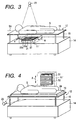
- Fig. 3 is a perspective view illustrating the use of a grid for preventing the scattering of X-rays, and in Fig. 3, the same reference numerals as those in Figs. 2A and 2B designate the same members.
- An X-ray image receiving portion 11' has an X-ray detector 21 and a grid 22 incorporated therein, and a vessel 23 emitting X-rays is movably provided above the top plate 16.
- the grid 22 comprises a plurality of strips of lead foil 22a arranged parallel to one another at predetermined equal intervals d, and the direction of arrangement of the lead foil 22a is made coincident with the widthwise direction of the top plate 16.
- the lengthwise direction of the lead foil 22a and the body axis S 0 of a subject S are made coincident with each other and a positional relation preferable to a clinical image is maintained.
- X-rays having entered the subject S from the vessel 23 are transmitted through the top plate 16 and thereafter enter the grid 22, and arrive at an X-ray detector 21 with their scattered rays removed.
- the grid 22 is moved in the lengthwise direction of the top plate 16, the positions of the lead foil 22a relative to the widethwise direction of the top plate 16 do not change and therefore, the lead foil 22a appears in the image. Therefore, it is necessary to move (e.g. pivotally move) the grid 22 in the direction of arrow A which is the widthwise direction of the top plate 16 in Fig. 3 in the X-ray image receiving portion 11' by driving means, not shown.
- the X-ray image receiving portion 11' When as shown in Fig. 4, the X-ray image receiving portion 11' is in a position for photographing a side of the subject S, the lengthwise direction of the lead foil 22a and the body axis S 0 of the subject S coincide with each other and the X-ray image receiving portion 11' maintains its preferable state. Also, when a side of the whole body of the subject S is to be photographed, the vessel 23 and the X-ray image receiving portion 11' are moved at a time.
- the grid 22 is held in a vertical position with respect to the lengthwise direction of the top plate 16 and they are moved at a time along the lengthwise direction of the head foil 22a, i.e., the lengthwise direction of the top plate 16, but the vessel 23 need not be accurately held in the vertical position relative to the X-ray image receiving portion 11' and therefore, the photographing work becomes easy.
- a spacer 24 of a predetermined thickness can be interposed between the top plate 16 and the subject S or provision can be made of a moving mechanism, not shown, for moving the X-ray image receiving portion 11' in the vertical direction. This adjusting work can be done before photographing and therefore, photographing can be done continuously.
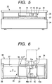
- Fig. 5 is a side view of a second embodiment of the present invention
- Fig. 6 is a partly cut-away plan view thereof
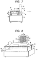
- Fig. 7 is a front view thereof
- an X-ray image receiving portion 31 is supported on a table 32 through a moving mechanism 33.
- the X-ray image receiving portion 31 and the table 32 are similar to those in the first embodiment, and in the table 32, a top plate 36 is supported on a supporting stand 34 through struts 35.
- a fixed rail stand 37 is fixed to the upper surface of the supporting stand 34 toward the lengthwise direction of the top plate 36, and a movable stand 38 is incorporated in the fixed rail stand 37 for movement in the direction of arrow C.
- a support shaft 39 is uprightly provided on the upper surface of one end portion of the movable stand 38, and a rotatable stand 40 is mounted on this support shaft 39 for rotation in the direction of arrow D.
- the rotatable stand 40 is of a flat T-shape, and the support shaft 39 is fitted in a hole in one end portion of the laterally long portion 40a of the T-shape of the rotatable stand 40.
- a support shaft 41 is provided parallel to the laterally long portion 40a, and the opposite end portions of the support shaft 41 are fitted in holes in the protruded portions 31a on the opposite sides of the X-ray image receiving portion 31, and the X-ray image receiving portion 31 is rotatable in the direction of arrow E of a horizontal position and a vertical position.
- the photographer positions the X-ray image receiving portion 31 below the top plate 36.
- the photographer rotates the X-ray image receiving portion 31 by 90° in the widthwise direction of the rotatable stand 40 and the top plate 36 to thereby expose the X-ray image receiving portion 31 from the lower portion of the top plate 36.
- the X-ray image receiving portion 31 is vertically erected by 90°. The side of the whole body of the subject is photographed while the erected X-ray image receiving portion 31 is moved in the lengthwise direction of the top plate 36 with the movable stand 38.
- This second embodiment can achieve an effect similar to that of the first embodiment and moreover can photograph the whole of the side of the subject.
- Fig. 8 is a perspective view illustrating the use of a grid for preventing the scattering of X-rays, and an X-ray image receiving portion 31' contains therein an X-ray detector 21 and a grid 22 similar to those in the first embodiment.
- the X-ray image receiving portion 31' is in a position for photographing a side of the subject S, the lengthwise direction of the lead foil 22a of the grid 22 differs by 90° from the direction of arrow C which is the direction of movement of the grid 22.
- the top plate 36 can be moved in the lengthwise direction instead of the X-ray image receiving portion 31' being moved in the lengthwise direction of the top plate 36. In this case, the photographing work becomes easy.
- the posture of the X-ray image receiving portions 11, 31 has been shown as being substantially vertically changed, whereas this is not restrictive, but if the posture of the X-ray image receiving portions 11, 31 is changed to an inclined angle which is not a right angle with respect to the top plates 16, 36, the subject S can be photographed from an oblique direction without the posture of the subject S being inclined with respect to the top plates 16, 36.
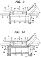
- a radiation image receiving portion 51 is movably supported on the bed 52 of an ICU through a moving mechanism 53.
- a top plate 56 is supported on the horizontal portion 54a of the supporting stand 54 of the bed 52 through struts 45, and casters 57 are provided on the lower ends of the legs 54b of the supporting stand 54, whereby the bed 52 is movable.
- An auxiliary breathing appliance such as an oxygen cylinder and a measuring appliance such as an electrocardiograph can be carried in a space 58 surrounded by the legs 54b of the supporting stand 54.
- the top plate 56 is comprised of a fixed top plate 59 positioned in the central portion in the lengthwise direction thereof, and movable top plates 62, 63 supported on the opposite end portions of the fixed top plate 59 through hinges 60, 61 for rotation in a vertical direction, and the movable top plates 62, 63 can be fixed at any angle.
- the moving mechanism 53 is comprised of a fixed rail stand 64 positioned in the central portion thereof, and movable rail stands 67, 68 supported on the opposite end portions of the fixed rail stand 64 through hinges 65, 66 for rotation in a vertical direction, and these movable rail stands 67, 68 can also be fixed at any angle.
- the fixed top plate 59 and the movable top plates 62, 63 form horizontal
- the fixed rail stand 64 and the movable rail stands 67, 68 also form horizontal
- the radiation image receiving portion 51 becomes movable to below the movable top plates 62, 63.
- the movable top plate 62 on which the upper half of the subject's body is positioned is erected by about 45° in a vertical direction, and as indicated by broken lines, the radiation image receiving portion 51 is moved and fixed onto the movable rail stand 67, which is then rotated and fixed so as to become parallel to the movable top plate 62.
- the photographer can photograph the subject from different directions without detaching the radiation image receiving portion 51 from the bed 52.
- the radiation image receiving portion 51 is moved only in the lengthwise direction of the top plate 56 and therefore, the space 69 between the supporting stand 54 and the top plate 56 can be narrowed. If in this case, as in the first and second embodiments, the radiation image receiving portion 51 is designed to be moved in the widthwise direction of the top plate 56 and erectile, side photographing will also become possible.
- Fig. 10 is a side view of a fourth embodiment of the present invention
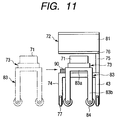
- Fig. 11 is a front view thereof, and provision is made of an X-ray image receiving portion 71, a bed 72 and a moving mechanism 73, and the bed 72 is provided with a supporting stand 74, struts 75, a top plate 76 and casters 77.
- the top plate 76 is provided with a fixed top plate 78, hinges 79, 80 and movable top plates 81, 82.
- the top plate 76 has its one side supported by two struts 75.
- the X-ray image receiving portion 71 and the moving mechanism 73 are supported on a second supporting stand 83 discrete from the bed 72.
- the second supporting stand 83 is removably insertable into the bed 72, and is comprised of a horizontal portion 83a located above the horizontal portion 74a of the supporting stand 74 of the bed 72, legs 83b located outwardly of the legs 74b of the supporting stand 74 of the bed 72, and casters 84 mounted on the lower ends of these legs 83b.
- the moving mechanism 73 is installed on the horizontal portion 83a of the second supporting stand 83, and this moving mechanism 73 is comprised of a fixed rail stand 85, hinges 86, 87 and movable rail stands 88, 89 similar to those in the third embodiment.
- the second supporting stand 83 can be moved to thereby locate the X-ray image receiving portion 71 below the top plate 76, and it is not necessary to incorporate the X-ray image receiving portion 71 into the table 72 from the first.
- the supporting stands 74 and 83 when the subject is to be photographed with the grid moved in the X-ray image receiving portion, it is necessary to fix the supporting stands 74 and 83 to each other, for example, by the use of a lock mechanism 90, and prevent their relative position from deviating during the movement of the grid. It is desirable that the fixing by the lock mechanism 90 be done at positions near the lengthwisely opposite ends of the horizontal portion 74a of the supporting stand 74. When the relative position of the supporting stand 74 supporting the subject thereon and the supporting stand 83 supporting the X-ray image receiving portion thereon deviates during photographing, the photographed image may be aggravated.
- fixing means like this lock mechanism need not always be provided.
- a photographing stand with a radiation image receiving portion has a lying stand having a top plate on which a subject lies down, a radiation image receiving portion located below the top plate, a moving mechanism for making the radiation image receiving portion movable in the widthwise direction or the lengthwise direction of the top plate, and an erecting mechanism for erecting the radiation image receiving portion in a vertical direction.
Landscapes
- Physics & Mathematics (AREA)
- General Physics & Mathematics (AREA)
- Apparatus For Radiation Diagnosis (AREA)
- Analysing Materials By The Use Of Radiation (AREA)
Applications Claiming Priority (4)
| Application Number | Priority Date | Filing Date | Title |
|---|---|---|---|
| JP22363698 | 1998-07-23 | ||
| JP22363698 | 1998-07-23 | ||
| JP8249899 | 1999-03-25 | ||
| JP8249899 | 1999-03-25 |
Publications (3)
| Publication Number | Publication Date |
|---|---|
| EP0974864A2 true EP0974864A2 (fr) | 2000-01-26 |
| EP0974864A3 EP0974864A3 (fr) | 2000-09-20 |
| EP0974864B1 EP0974864B1 (fr) | 2005-06-15 |
Family
ID=26423509
Family Applications (1)
| Application Number | Title | Priority Date | Filing Date |
|---|---|---|---|
| EP99114438A Expired - Lifetime EP0974864B1 (fr) | 1998-07-23 | 1999-07-22 | Support photographique muni d'une partie réceptrice pour images obtenues par rayonnement |
Country Status (3)
| Country | Link |
|---|---|
| US (1) | US6341893B1 (fr) |
| EP (1) | EP0974864B1 (fr) |
| DE (1) | DE69925786T2 (fr) |
Families Citing this family (7)
| Publication number | Priority date | Publication date | Assignee | Title |
|---|---|---|---|---|
| US6603988B2 (en) * | 2001-04-13 | 2003-08-05 | Kelsey, Inc. | Apparatus and method for delivering ablative laser energy and determining the volume of tumor mass destroyed |
| JP3624173B2 (ja) * | 2001-07-26 | 2005-03-02 | キヤノン株式会社 | 放射線画像撮影装置 |
| US6899459B1 (en) * | 2002-07-18 | 2005-05-31 | Analogic Corporation | Bucky presentation assembly for patient table |
| US7041109B2 (en) * | 2002-12-12 | 2006-05-09 | Kelsey, Inc. | Apparatus and method for interstitial laser therapy of small breast cancers and adjunctive therapy |
| EP2131773B1 (fr) | 2007-02-05 | 2011-11-23 | Novian Health Inc. | Coffrets de therapie laser interstitielle et systeme de commande de therapie laser interstitielle |
| US8092507B2 (en) | 2007-02-05 | 2012-01-10 | Novian Health, Inc. | Interstitial energy treatment probe holders |
| JP7030478B2 (ja) * | 2017-11-09 | 2022-03-07 | キヤノン株式会社 | 撮影台および放射線撮影システム |
Family Cites Families (13)
| Publication number | Priority date | Publication date | Assignee | Title |
|---|---|---|---|---|
| US3397411A (en) * | 1965-09-21 | 1968-08-20 | Generay Gen Radiologica | Patient-supporting device for radiological treatments |
| US4468803A (en) | 1982-09-29 | 1984-08-28 | Ronci Mary R | X-Ray film cassette frame suspension apparatus |
| US4760591A (en) | 1986-05-19 | 1988-07-26 | B. F. Wehmer Co., Inc. | Cephalostat for cephalometric roentgenography |
| US4905266A (en) * | 1988-01-29 | 1990-02-27 | Midmark Corporation | Film cartridge support for bed-like stretcher |
| DE8900948U1 (de) * | 1989-01-27 | 1989-03-23 | Siemens AG, 1000 Berlin und 8000 München | Röntgendiagnostikgerät für Mammographieaufnahmen |
| US5014292A (en) * | 1990-01-29 | 1991-05-07 | Siczek Bernard W | Tiltable x-ray table integrated with carriage for x-ray source and receptor |
| JP2688123B2 (ja) * | 1991-04-19 | 1997-12-08 | 富士写真フイルム株式会社 | 放射線画像情報記録読取装置 |
| JPH0767870A (ja) * | 1993-09-02 | 1995-03-14 | Sony Corp | 医用検査装置と医用検査装置の患者テーブルの移動検出方法 |
| US5764724A (en) * | 1994-07-28 | 1998-06-09 | Ao Medical Products Ab | Method of making X-ray photographs or exposures or other type of radiation sensoring, such as electronic image storage, and a patient table having a receptor unit for such photography, exposure or image storage |
| US5537454A (en) * | 1994-12-27 | 1996-07-16 | Med-Tec, Inc. | Radiation therapy grid for use with treatment couch |
| US6027247A (en) * | 1995-04-04 | 2000-02-22 | Hitachi Medical Corporation | X-ray photographing apparatus |
| EP0788767B1 (fr) * | 1996-02-06 | 2003-04-16 | Philips Corporate Intellectual Property GmbH | Appareil diagnostique à rayons X |
| JPH10258049A (ja) * | 1997-03-19 | 1998-09-29 | Hitachi Medical Corp | 医用診断装置の寝台制御装置 |
-
1999
- 1999-07-20 US US09/356,699 patent/US6341893B1/en not_active Expired - Lifetime
- 1999-07-22 EP EP99114438A patent/EP0974864B1/fr not_active Expired - Lifetime
- 1999-07-22 DE DE69925786T patent/DE69925786T2/de not_active Expired - Lifetime
Also Published As
| Publication number | Publication date |
|---|---|
| EP0974864A3 (fr) | 2000-09-20 |
| EP0974864B1 (fr) | 2005-06-15 |
| DE69925786D1 (de) | 2005-07-21 |
| DE69925786T2 (de) | 2006-05-18 |
| US6341893B1 (en) | 2002-01-29 |
Similar Documents
| Publication | Publication Date | Title |
|---|---|---|
| EP0557981B1 (fr) | Appareil à rayons X pour utilisation médicale | |
| JP4810182B2 (ja) | 放射線撮影装置 | |
| EP1643305A1 (fr) | Appareil pour rayons-x | |
| US6592257B1 (en) | Detachable device for radiological digital imaging | |
| JP2000037374A (ja) | 放射線撮影装置 | |
| EP0974864B1 (fr) | Support photographique muni d'une partie réceptrice pour images obtenues par rayonnement | |
| EP0135723A1 (fr) | Appareil photographique pour image de radiation | |
| JP4497677B2 (ja) | 放射線撮影装置 | |
| JP4574202B2 (ja) | 放射線撮影支持台 | |
| JP4454970B2 (ja) | X線画像撮影装置 | |
| CA2351534A1 (fr) | Appareil et procede de positionnement d'une mosaique de detecteurs de rayons x numeriques | |
| JP2002214747A (ja) | 画像を揃える補助器具を有するコンピューテッド・ラジオグラフィ用の細長いカセッテ | |
| JP2005261666A (ja) | 放射線画像撮影装置 | |
| JP3592145B2 (ja) | 放射線受像部付撮影台 | |
| WO1987003795A1 (fr) | Procede et dispositif de radiographie, utilisant un montant de support mobile dans le voisinage d'une table d'examen pour patient | |
| JP2005000371A (ja) | 放射線撮影装置 | |
| JP4360006B2 (ja) | X線透視撮影台 | |
| JP3631075B2 (ja) | 放射線受像部付撮影台 | |
| JP2003010164A (ja) | X線撮影装置 | |
| JP2000037382A (ja) | ブッキー撮影台 | |
| JP3772705B2 (ja) | X線透視撮影装置 | |
| JP2000245720A (ja) | 放射線撮影装置 | |
| JPH0612735Y2 (ja) | X線透視撮影装置 | |
| JP3207050B2 (ja) | 断層x線撮影装置 | |
| JP3853647B2 (ja) | 放射線透過撮影装置 |
Legal Events
| Date | Code | Title | Description |
|---|---|---|---|
| PUAI | Public reference made under article 153(3) epc to a published international application that has entered the european phase |
Free format text: ORIGINAL CODE: 0009012 |
|
| AK | Designated contracting states |
Kind code of ref document: A2 Designated state(s): DE FR GB IT NL |
|
| AX | Request for extension of the european patent |
Free format text: AL;LT;LV;MK;RO;SI |
|
| PUAL | Search report despatched |
Free format text: ORIGINAL CODE: 0009013 |
|
| AK | Designated contracting states |
Kind code of ref document: A3 Designated state(s): AT BE CH CY DE DK ES FI FR GB GR IE IT LI LU MC NL PT SE |
|
| AX | Request for extension of the european patent |
Free format text: AL;LT;LV;MK;RO;SI |
|
| 17P | Request for examination filed |
Effective date: 20010130 |
|
| AKX | Designation fees paid |
Free format text: DE FR GB IT NL |
|
| 17Q | First examination report despatched |
Effective date: 20040316 |
|
| GRAP | Despatch of communication of intention to grant a patent |
Free format text: ORIGINAL CODE: EPIDOSNIGR1 |
|
| GRAS | Grant fee paid |
Free format text: ORIGINAL CODE: EPIDOSNIGR3 |
|
| GRAA | (expected) grant |
Free format text: ORIGINAL CODE: 0009210 |
|
| AK | Designated contracting states |
Kind code of ref document: B1 Designated state(s): DE FR GB IT NL |
|
| REG | Reference to a national code |
Ref country code: GB Ref legal event code: FG4D |
|
| REF | Corresponds to: |
Ref document number: 69925786 Country of ref document: DE Date of ref document: 20050721 Kind code of ref document: P |
|
| ET | Fr: translation filed | ||
| PLBE | No opposition filed within time limit |
Free format text: ORIGINAL CODE: 0009261 |
|
| STAA | Information on the status of an ep patent application or granted ep patent |
Free format text: STATUS: NO OPPOSITION FILED WITHIN TIME LIMIT |
|
| 26N | No opposition filed |
Effective date: 20060316 |
|
| PGFP | Annual fee paid to national office [announced via postgrant information from national office to epo] |
Ref country code: NL Payment date: 20140630 Year of fee payment: 16 Ref country code: DE Payment date: 20140731 Year of fee payment: 16 |
|
| PGFP | Annual fee paid to national office [announced via postgrant information from national office to epo] |
Ref country code: FR Payment date: 20140728 Year of fee payment: 16 Ref country code: GB Payment date: 20140724 Year of fee payment: 16 |
|
| PGFP | Annual fee paid to national office [announced via postgrant information from national office to epo] |
Ref country code: IT Payment date: 20140702 Year of fee payment: 16 |
|
| REG | Reference to a national code |
Ref country code: DE Ref legal event code: R119 Ref document number: 69925786 Country of ref document: DE |
|
| GBPC | Gb: european patent ceased through non-payment of renewal fee |
Effective date: 20150722 |
|
| REG | Reference to a national code |
Ref country code: NL Ref legal event code: MM Effective date: 20150801 |
|
| PG25 | Lapsed in a contracting state [announced via postgrant information from national office to epo] |
Ref country code: IT Free format text: LAPSE BECAUSE OF NON-PAYMENT OF DUE FEES Effective date: 20150722 Ref country code: DE Free format text: LAPSE BECAUSE OF NON-PAYMENT OF DUE FEES Effective date: 20160202 Ref country code: GB Free format text: LAPSE BECAUSE OF NON-PAYMENT OF DUE FEES Effective date: 20150722 |
|
| REG | Reference to a national code |
Ref country code: FR Ref legal event code: ST Effective date: 20160331 |
|
| PG25 | Lapsed in a contracting state [announced via postgrant information from national office to epo] |
Ref country code: FR Free format text: LAPSE BECAUSE OF NON-PAYMENT OF DUE FEES Effective date: 20150731 Ref country code: NL Free format text: LAPSE BECAUSE OF NON-PAYMENT OF DUE FEES Effective date: 20150801 |