EP0974886A2 - Mécanisme pour pédale - Google Patents
Mécanisme pour pédale Download PDFInfo
- Publication number
- EP0974886A2 EP0974886A2 EP99305763A EP99305763A EP0974886A2 EP 0974886 A2 EP0974886 A2 EP 0974886A2 EP 99305763 A EP99305763 A EP 99305763A EP 99305763 A EP99305763 A EP 99305763A EP 0974886 A2 EP0974886 A2 EP 0974886A2
- Authority
- EP
- European Patent Office
- Prior art keywords
- pedal
- arm
- pedal mechanism
- friction
- base
- Prior art date
- Legal status (The legal status is an assumption and is not a legal conclusion. Google has not performed a legal analysis and makes no representation as to the accuracy of the status listed.)
- Granted
Links
- 230000007246 mechanism Effects 0.000 title claims abstract description 80
- 239000004033 plastic Substances 0.000 claims description 20
- 229920003023 plastic Polymers 0.000 claims description 20
- 230000006835 compression Effects 0.000 claims description 11
- 238000007906 compression Methods 0.000 claims description 11
- 239000000463 material Substances 0.000 claims description 9
- 230000002708 enhancing effect Effects 0.000 claims description 4
- 238000013016 damping Methods 0.000 claims description 2
- XDDAORKBJWWYJS-UHFFFAOYSA-N glyphosate Chemical compound OC(=O)CNCP(O)(O)=O XDDAORKBJWWYJS-UHFFFAOYSA-N 0.000 description 17
- 230000008901 benefit Effects 0.000 description 7
- 238000010276 construction Methods 0.000 description 5
- 238000004519 manufacturing process Methods 0.000 description 5
- 238000001746 injection moulding Methods 0.000 description 4
- 239000007787 solid Substances 0.000 description 4
- 229910000831 Steel Inorganic materials 0.000 description 3
- 230000001419 dependent effect Effects 0.000 description 3
- 238000010586 diagram Methods 0.000 description 3
- 239000003365 glass fiber Substances 0.000 description 3
- 238000002347 injection Methods 0.000 description 3
- 239000007924 injection Substances 0.000 description 3
- 239000010959 steel Substances 0.000 description 3
- 229920002430 Fibre-reinforced plastic Polymers 0.000 description 2
- 238000004458 analytical method Methods 0.000 description 2
- 238000004364 calculation method Methods 0.000 description 2
- 230000008859 change Effects 0.000 description 2
- 230000001276 controlling effect Effects 0.000 description 2
- 239000000446 fuel Substances 0.000 description 2
- 238000009434 installation Methods 0.000 description 2
- 230000010354 integration Effects 0.000 description 2
- 238000000034 method Methods 0.000 description 2
- 230000008569 process Effects 0.000 description 2
- 230000000630 rising effect Effects 0.000 description 2
- 229910000639 Spring steel Inorganic materials 0.000 description 1
- 230000001133 acceleration Effects 0.000 description 1
- 230000004913 activation Effects 0.000 description 1
- 230000005540 biological transmission Effects 0.000 description 1
- 230000015556 catabolic process Effects 0.000 description 1
- 239000011248 coating agent Substances 0.000 description 1
- 238000000576 coating method Methods 0.000 description 1
- 238000002485 combustion reaction Methods 0.000 description 1
- 150000001875 compounds Chemical group 0.000 description 1
- 239000002826 coolant Substances 0.000 description 1
- 230000000994 depressogenic effect Effects 0.000 description 1
- 238000002474 experimental method Methods 0.000 description 1
- 230000006872 improvement Effects 0.000 description 1
- 238000005461 lubrication Methods 0.000 description 1
- 239000002184 metal Substances 0.000 description 1
- 239000002991 molded plastic Substances 0.000 description 1
- 230000007935 neutral effect Effects 0.000 description 1
- 230000007363 regulatory process Effects 0.000 description 1
- 239000011347 resin Substances 0.000 description 1
- 229920005989 resin Polymers 0.000 description 1
- 230000000284 resting effect Effects 0.000 description 1
- 239000005060 rubber Substances 0.000 description 1
- 238000007789 sealing Methods 0.000 description 1
- 238000005507 spraying Methods 0.000 description 1
- 230000000007 visual effect Effects 0.000 description 1
Images


Classifications
-
- G—PHYSICS
- G05—CONTROLLING; REGULATING
- G05G—CONTROL DEVICES OR SYSTEMS INSOFAR AS CHARACTERISED BY MECHANICAL FEATURES ONLY
- G05G1/00—Controlling members, e.g. knobs or handles; Assemblies or arrangements thereof; Indicating position of controlling members
- G05G1/30—Controlling members actuated by foot
- G05G1/38—Controlling members actuated by foot comprising means to continuously detect pedal position
-
- G—PHYSICS
- G05—CONTROLLING; REGULATING
- G05G—CONTROL DEVICES OR SYSTEMS INSOFAR AS CHARACTERISED BY MECHANICAL FEATURES ONLY
- G05G5/00—Means for preventing, limiting or returning the movements of parts of a control mechanism, e.g. locking controlling member
- G05G5/03—Means for enhancing the operator's awareness of arrival of the controlling member at a command or datum position; Providing feel, e.g. means for creating a counterforce
-
- Y—GENERAL TAGGING OF NEW TECHNOLOGICAL DEVELOPMENTS; GENERAL TAGGING OF CROSS-SECTIONAL TECHNOLOGIES SPANNING OVER SEVERAL SECTIONS OF THE IPC; TECHNICAL SUBJECTS COVERED BY FORMER USPC CROSS-REFERENCE ART COLLECTIONS [XRACs] AND DIGESTS
- Y10—TECHNICAL SUBJECTS COVERED BY FORMER USPC
- Y10T—TECHNICAL SUBJECTS COVERED BY FORMER US CLASSIFICATION
- Y10T74/00—Machine element or mechanism
- Y10T74/20—Control lever and linkage systems
- Y10T74/20528—Foot operated
- Y10T74/20534—Accelerator
-
- Y—GENERAL TAGGING OF NEW TECHNOLOGICAL DEVELOPMENTS; GENERAL TAGGING OF CROSS-SECTIONAL TECHNOLOGIES SPANNING OVER SEVERAL SECTIONS OF THE IPC; TECHNICAL SUBJECTS COVERED BY FORMER USPC CROSS-REFERENCE ART COLLECTIONS [XRACs] AND DIGESTS
- Y10—TECHNICAL SUBJECTS COVERED BY FORMER USPC
- Y10T—TECHNICAL SUBJECTS COVERED BY FORMER US CLASSIFICATION
- Y10T74/00—Machine element or mechanism
- Y10T74/20—Control lever and linkage systems
- Y10T74/20576—Elements
- Y10T74/20888—Pedals
Definitions
- This invention relates to a pedal mechanism.
- the invention is particularly, but not exclusively, intended for use in a motor vehicle, for controlling a function of the vehicle.
- the pedal may be an accelerator pedal.
- the accelerator pedal can be formed in one or more parts and is conventionally mounted in a floor assembly of the driver cell of a motor vehicle.
- the throttle plate is opened by the driver's foot pressure on the accelerator pedal.
- One or two resetting springs are provided to draw the accelerator pedal and thus the throttle plate back to an idling position when the driver's foot is lifted. In this way a link is provided between the pedal and throttle plate position on the one hand and a change in the engine speed on the other hand.
- Pedal mechanisms wherein the friction force is produced by means of separate pretensioned friction elements (e.g. DE 3 411 456 C2). Arrangements of this kind are complicated in construction and limiting for the size of the friction force. It is also important that if one spring breaks then a satisfactory and safe resetting must be possible.
- the safe resetting in the event of a spring breaking is an absolute necessity for reasons of product liability and is a legal requirement in the USA through safety standard FMVSS124.
- This arrangement requires several parts movable relative to each other and cannot be integrated in the pedal structure as a result of the large installation space required.
- the invention therefore seeks to provide a pedal mechanism which transfers the pedal position simply and precisely to for example an electronic engine control unit whilst the driving feel remains unchanged compared to conventional regulating processes.
- An object of the invention is to design a pedal mechanism so that the resetting force of the resetting elements is used directly to produce the friction force. Furthermore the friction mechanism is to be capable of integration in the pedal so that no additional structural or sealing elements are required to protect the friction mechanism from dirt. Furthermore the pedal bearing should be precise with neutral wear and able to be manufactured cost-effectively. The unavoidable wear to the highly-stressed friction faces producing the pedal friction required for reasons of comfort should not change the play or accuracy of the pedal mechanism throughout its service life.
- a pedal mechanism comprising a pedal arm pivoted on a base, an auxiliary arm also pivoted on the base, on a pivot axis parallel to but spaced from the pedal arm axis, and biasing means acting between the base and the auxiliary arm, to bias the auxiliary arm into frictional contact with the pedal arm, and a sensor adapted to sense the position of the pedal arm and to output a pedal position signal.
- the pivot axis of the pedal arm preferably lies between the pedal foot pad and the auxiliary arm pivot axis.
- the auxiliary arm preferably has a friction enhancing surface where it makes contact with the pedal arm, and/or the pedal arm has a friction enhancing surface where it makes contact with the auxiliary arm.
- the biasing means can comprise at least one helical compression spring tensioned between the auxiliary arm and the base. There may be two such springs arranged side by side with their ends supported in annular grooves. In another embodiment, the springs are fixed by retaining dome covers. The springs can be helical compression springs of different diameters with one spring fitted inside the other.
- the base can be moulded from a plastics material such as glass fibre reinforced resin.
- the pedal arm and the auxiliary arm are moulded from a plastics material such as glass fibre reinforced resin.
- End stops for pedal arm movement can be mounted on the base, the end stops cooperating with a part of the pedal arm which lies on the opposite side of the pedal arm axis to the foot pad.
- the end stops can consist of an elastic noise-damping material.
- the pedal position sensor can be mounted on the base adjacent the end stops, and can be mounted to enable it to be rotated to set an accurate rest position.
- the base can have a screw-on flange for holding the position sensor.
- the pedal mechanism can include a device (eg a kick-down device) for producing a rise in the pressure required to depress the pedal arm, over part of the pedal arm travel.
- the device can be located in a recess in the pedal arm.
- the pedal mechanism can be specifically adapted to function as an accelerator pedal mechanism, for a motor vehicle.
- the drawings show an accelerator pedal mechanism with an integrated position sensor for controlling the power of a drive machine.
- the drive machine can be an electric, petrol or diesel engine.
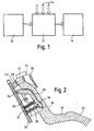
- the block 10 represents a sensor module which senses the pedal position. This module generates a signal representing pedal position which is passed to an engine control module 12.
- the module 12 also receives other signals 14 from other sensors representing eg engine coolant temperature, ambient temperature, manifold vacuum. The module 12 evaluates all these signals and then produces an output signal which is fed to a throttle valve unit 16, or to a fuel injection pump in the case of a diesel engine.
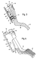
- the pedal mechanism has a swivel pedal arm 18 which can swivel about a swivel axis 20 at one end and has a pad 22 for contact with the driver's foot at the other end.
- the pedal can be moved against a rising resetting force, produced by two resetting springs, from a rest position ( Figure 2 - idle position) into an end position ( Figure 3 - wide open throttle).
- Figure 2 shows a base 24 in which the pedal arm 18 is mounted to pivot about the pedal axis 20.
- the base also has a pivot axis 26 for an auxiliary or friction arm 28.
- Resetting elements in the form of helical compression springs 30,32 are mounted between the base 24 and the friction arm 28 so that the friction arm is always urged in the direction of the rest position of Figure 2.
- the friction arm 28 has a friction surface 34 which is pressed against the underside of the pedal arm 18, at a region where the pedal arm also has a friction surface 36.
- the friction force is dependent on the pretension force of the reset springs 30,32, the engagement angle ⁇ between the pedal arm 18 and the friction arm 28 and on the coefficient of friction ( ⁇ ) between the friction arm and the pedal arm.
- the pretension force of the resetting spring elements 30,32 and the force components of the friction force acting tangentially to the pedal axis 20 produce the pedal moment.
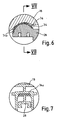
- Figure 6 shows that the friction arm 28 can have a special friction modified coating at 34a, just on the surface of the arm which makes contact with the underside of the pedal arm 18.
- a pedal mechanism as described above can have in particular the following advantages:
- FIGs 8,9 and 10 show a kick-down mechanism and the way in which this also acts as an end stop to limit pedal travel against the restoring force of the springs 30,32.
- the pedal arm 18 here has a socket 53 at right angles to the pedal pivot axis.
- a kick-down spring unit 54 is fitted. This unit provides the extra resistance to pedal depression which signals to the driver that kick-down is being activated.
- the unit 54 has a base 56 with a shoulder 60 which fits inside the socket in the pedal arm.
- a cap 62 fits onto the base and is normally biased upwards, away from the base, to the position shown in Figure 9.
- a coil spring (not shown) is fitted in a recess 66 to do this.
- the cap 62 contacts the end stop 38 on an inner surface of the housing 48.
- To move the pedal further requires the driver to overcome not only the resistance of the springs 30, 32 and the friction between the pedal and friction arms, but also to compress the spring in the recess 66.
- the pedal mechanism is shown fitted with two helical or coil compression springs 30,32. Springs of this kind can be made cost-effectively and with great precision.
- springs 30,32 can be made cost-effectively and with great precision.
- In conjunction with the generation of friction through the friction arm 28 it is possible to produce a pedal operating force and pedal friction with very great precision without additional pretensioning elements and without the need for an adjustment, which is very advantageous for large scale mass production.
- this design of pedal mechanism offers through the optimum design of the driver/vehicle interface with regard to the ergonomic design and behaviour of the pedal considerable advantages over the prior art, where the friction is generally produced with additional friction and pretensioning elements, and thus has great tolerances.
- the pedal mechanism can optionally be provided with a kick-down unit, which produces a force rise according to the diagram shown in Figure 11 (Figure 11 area B) and the force drop after overcoming the force peak (Figure 11 area C).
- the stages shown in Figure 11 are: A Operating Force KD Kick-down activation B Kick-down force increase C Kick-down force drop after overshooting the threshold D Holding force A-D Pedal force hysteresis Pedal force hysteresis 2 * pedal friction torque/pedal radius
- the pedal bearing and the friction arm bearing can be formed by plastics pins inserted through matching holes on opposite sides of the pedal housing 48. Another similar pin can be inserted through holes on opposite sides of the housing to form an end stop for the pedal at the idle end of its travel.
- the pedal operating force which can be felt by the driver corresponds to the pedal force divided by the active pedal radius.
- the driver feels the pedal resetting force produced by the resetting elements, the resetting force plus the tangentially acting friction force components and in the direction of reducing acceleration or holding the accelerator pedal position the driver feels the pedal force produced by the resetting elements minus the tangentially acting friction force components since the friction force always acts against the direction of movement.
- resetting elements shown to produce the friction force allows the pedal operating and holding forces to be produced solely from ergonomic points of view. If a resetting element should fail, the pedal friction will be reduced at the same time so that safe resetting of the pedal in the event of a break in one resetting element is ensured. This is also in part a legal requirement (e.g. in the USA through FMVSS 124).
- a solid plastics construction of a pedal mechanism is illustrated in the examples.
- the design of the friction arm and the integration thereof into the pedal structure allows an extremely stiff structure which is extremely lightweight and suited to plastics.
- the weight of this structure can amount to about 250 g.
- Comparable structures with steel pedal and adapted pedal sensor which are generally used nowadays are significantly heavier and on average weigh about > 750g.
- the resetting elements are illustrated by two coil compression springs 30,32. They can be made cost-effectively with high precision. When designed in stainless valve spring steel (as is preferred), calculation and construction for permanent strength are possible without problem.
- the coil compression springs are mounted side by side and fixed in ring-shaped recesses in the friction arm 28 and in the assembly base 24.
- the two coil compression springs one inside the other (small spring in large spring). Fixing the large outer spring can then be through a ring-shaped recess in the friction arm and in the assembly base. The smaller inner spring is then fixed on retaining pins in the assembly base and on the friction arm.
- the pedal arm is designed as a one-piece plastics part 18 including a recess 42 for optional fitting with a kick-down element and a pedal position sensor 44.
- the sensor 44 can be adapted in shape and design without additional costs in an optimum manner to customer requirements.
- Figures 4 and 5 show a foot or pedal pad 22 which has a ribbed design combined with a slightly rounded pedal contour which produces an optimum ergonomic pedal shape.
- the openwork structure indicated by avoiding large wall thickness, allows reliable manufacture in an injection moulding process with maximum stiffness and lowest possible weight. This structure could be optimised by finite element analysis so that for each different design, accurately defined boundary values can be given for permanent and peak load.
- the pedal arm 18 is carried on a bearing shaft 20 which is set in a bore in the pedal arm and in bores 46 in side walls 48 of the assembly base 24.
- This shaft does not have to rotate it can be made from either steel or plastics (e.g. as an injection-moulded part).
- the bolt When made from steel the bolt is advantageously milled on one side and has a pressed seat in the assembly base.
- the bore in the pedal arm is formed with clearance.
- the fittings in the pedal arm 18 and in the assembly base 24 are designed as clearance fittings.
- the axial fixed seat of the bearing bolt is ensured through a radially mounted detent nose (not shown) on the bearing bolt which engages in a recess (not shown) in the pedal arm.
- the position sensor 44 is for reasons of bearing precision and standardisation formed as a separate component part with its own bearing and its own housing. It is screwed by means of screws onto correspondingly formed screw-on dome covers of the assembly base and is adjusted through screw-on flange bores formed as oblong holes in the rest position to an accurately specified starting signal through turning and then screw-tightening.
- the mechanical transfer of the pedal travel by the position sensor takes place through a conventional lever mechanism or spur wheel gearing.
- the assembly base has a plastics flange in which corresponding assembly bores 50 are provided which are readily accessible from above. It is advantageous if threaded bolts are prefixed on the vehicle body structure so that during assembly the pedal mechanism is already pre-centred. So that it becomes possible, for reasons of weight and costs, to dispense with the present day conventional metal sleeves in the assembly bores which are to prevent overstraining the plastics during screw-tightening, so-called squeeze nuts are used for fitting. It is thus possible to secure the pedal mechanism by tightening the nuts to a predetermined torque which guarantees a reliable fixed seat of the pedal mechanism but does not overstrain the glass fibre reinforced plastics in the area of the screw-in bores.
- the stop for the pedal travel in the rest or idle position is integrated through suitably designed faces into the pedal arm and assembly base 40,52.
- these parts By making these parts as injection moulded parts the smallest possible tolerances are produced for the stop in the rest position.
- This has the advantage that with a corresponding tolerance provision in the vehicle the smallest possible bearing tolerances are produced for the spatial arrangement of the pedal mechanism in relation to the position of the brake.
- This has a significant advantage especially with high-performance vehicles since a more accurate vertical distance between the brake pedal and the accelerator pedal helps to avoid accidental simultaneous operation of the accelerator and brake pedal, and thus prevents the engine power overcoming the brake power and the vehicle from accelerating undesirably.
- the design of the pedal mechanism according to the invention therefore has the idling stop and full load stop integrated into the pedal mechanism. Since the tolerances for the pedal travel in the embodiment illustrated in Figure 3 are produced substantially by the position of the integrated stops 38,40 in only two ready to use parts which can be made with high precision in the injection moulding process, the pedal arm 18 and assembly base 24, it is evident that low tolerances for the pedal travel can be produced without any subsequent adjustment required in the vehicle.
- the critical point when integrating the full load stop into the pedal mechanism is that all the pedal forces which act on the pedal have to be absorbed solely through the pedal mechanism including its housing structure in the vehicle.
- the accelerator pedal represents a safety-critical structural group it immediately follows from this that the pedal mechanism including its housing structure in the vehicle must have a very high rigidity and the load boundaries have to be clearly proved through calculation and guaranteed through precision defined processes in production.
- the pedal lies centrally between two extremely stiff side walls 48 which form bearing positions. By avoiding torsional forces in the pedal and in the assembly base maximum stiffness is produced with the lowest possible weight.
- a framework structure for the pedal can be optimised in the area of the operating part and a box structure can be optimised in the area of the bearing and friction mechanism.
- the pedal mechanism described thus offers good 'feel' to the driver, together with low cost, low weight and accurate reliable performance.
Landscapes
- Physics & Mathematics (AREA)
- General Physics & Mathematics (AREA)
- Engineering & Computer Science (AREA)
- Automation & Control Theory (AREA)
- Mechanical Control Devices (AREA)
- Auxiliary Drives, Propulsion Controls, And Safety Devices (AREA)
Applications Claiming Priority (2)
| Application Number | Priority Date | Filing Date | Title |
|---|---|---|---|
| GB9815705 | 1998-07-21 | ||
| GB9815705A GB2339887B (en) | 1998-07-21 | 1998-07-21 | Pedal mechanism |
Publications (3)
| Publication Number | Publication Date |
|---|---|
| EP0974886A2 true EP0974886A2 (fr) | 2000-01-26 |
| EP0974886A3 EP0974886A3 (fr) | 2002-04-17 |
| EP0974886B1 EP0974886B1 (fr) | 2004-09-15 |
Family
ID=10835780
Family Applications (1)
| Application Number | Title | Priority Date | Filing Date |
|---|---|---|---|
| EP99305763A Revoked EP0974886B1 (fr) | 1998-07-21 | 1999-07-21 | Mécanisme pour pédale |
Country Status (4)
| Country | Link |
|---|---|
| US (1) | US6289762B1 (fr) |
| EP (1) | EP0974886B1 (fr) |
| DE (1) | DE69920115T2 (fr) |
| GB (1) | GB2339887B (fr) |
Cited By (17)
| Publication number | Priority date | Publication date | Assignee | Title |
|---|---|---|---|---|
| WO2003040848A1 (fr) | 2001-11-06 | 2003-05-15 | Caithness Development Limited | Mecanisme de pedale |
| WO2003040849A1 (fr) * | 2001-11-06 | 2003-05-15 | Caithness Development Limited | Appareil de butee au ralenti |
| DE10218627A1 (de) * | 2002-04-25 | 2003-11-06 | Siemens Ag | Fahrpedaleinheit |
| WO2004107079A1 (fr) * | 2003-05-29 | 2004-12-09 | Cts Corporation | Pedale d'accelerateur pour vehicule a moteur |
| US6860170B2 (en) * | 2002-09-09 | 2005-03-01 | Dura Global Technologies, Inc. | Electronic throttle control hysteresis mechanism |
| DE10360784A1 (de) * | 2003-12-23 | 2005-08-04 | Audi Ag | Vorrichtung zum Ausrücken und Einrücken der Kupplung eines Kraftfahrzeuges |
| DE102004025829A1 (de) * | 2004-05-24 | 2005-12-22 | Ab Elektronik Gmbh | Pedaleinheit, Pedalbaugruppe und Kraftfahrzeug |
| EP1942390A1 (fr) * | 2003-05-29 | 2008-07-09 | CTS Corporation | Pédale d'accélérateur pour véhicule motorisé |
| EP2075665A1 (fr) | 2007-12-05 | 2009-07-01 | Sistemi Comandi Meccanici S.C.M. S.p.A. | Dispositif pour faire varier la résistance à la dépression de la pédale d'accélérateur d'un véhicule à moteur |
| US8042430B2 (en) | 2004-05-27 | 2011-10-25 | Cts Corporation | Accelerator pedal for a vehicle |
| US8528443B2 (en) | 2004-05-27 | 2013-09-10 | Cts Corporation | Accelerator pedal for a vehicle and mounting rack therefor |
| US8806977B2 (en) | 2011-10-07 | 2014-08-19 | Cts Corporation | Vehicle pedal assembly with hysteresis assembly |
| WO2018039098A1 (fr) * | 2016-08-22 | 2018-03-01 | Cts Corporation | Pédale d'embrayage de véhicule électronique à force variable |
| EP2390752B1 (fr) * | 2006-02-02 | 2018-04-18 | CTS Corporation | Pédale d'accélérateur pour véhicule |
| IT201700052700A1 (it) * | 2017-05-16 | 2018-11-16 | Bitron Spa | Pedale acceleratore, in particolare per un autoveicolo, provvisto di un dispositivo di realizzazione isteresi meccanica. |
| WO2019096387A1 (fr) * | 2017-11-16 | 2019-05-23 | HELLA GmbH & Co. KGaA | Pédale pour un véhicule |
| EP4159558A1 (fr) * | 2021-09-29 | 2023-04-05 | KNORR-BREMSE Systeme für Nutzfahrzeuge GmbH | Dispositif de frein au pied pour véhicules |
Families Citing this family (49)
| Publication number | Priority date | Publication date | Assignee | Title |
|---|---|---|---|---|
| DE19909476C2 (de) * | 1999-03-04 | 2001-05-10 | Mannesmann Vdo Ag | Modul mit Krafthysterese |
| JP3609302B2 (ja) * | 1999-10-18 | 2005-01-12 | アルプス電気株式会社 | 角度検出装置 |
| US6523433B1 (en) * | 1999-11-23 | 2003-02-25 | William C. Staker | Electronic pedal assembly and method for providing a tuneable hysteresis force |
| US6857336B2 (en) * | 1999-11-23 | 2005-02-22 | William C. Staker | Electronic pedal assembly and method for providing a tuneable hystersis force |
| DE19958241A1 (de) * | 1999-12-03 | 2001-08-09 | Methode Electronics Malta Ltd | Pedaleinrichtung für ein Kraftfahrzeug mit einem wegaufnehmenden Sensor |
| GB0010116D0 (en) * | 2000-04-27 | 2000-06-14 | Caithness Dev Limited | Pedal mechanism |
| JP2002048232A (ja) * | 2000-08-02 | 2002-02-15 | Jatco Transtechnology Ltd | 無段変速機の変速制御装置 |
| DE10105265B4 (de) * | 2001-02-02 | 2007-01-04 | ZF Lemförder Metallwaren AG | Rückstellvorrichtung für Pedale eines Kraftfahrzeuges |
| JP4010485B2 (ja) * | 2001-03-21 | 2007-11-21 | ボッシュ株式会社 | ブレーキペダル装置 |
| DE10212904A1 (de) * | 2001-03-23 | 2002-10-24 | Aisin Seiki | Beschleunigerpedalvorrichtung |
| WO2004007929A2 (fr) * | 2002-07-17 | 2004-01-22 | Ksr International Co. | Commande d'accelerateur electronique comprenant un dispositif d'hysteresis |
| KR100471863B1 (ko) * | 2002-10-04 | 2005-03-08 | 현대자동차주식회사 | 답력 조절 기능을 갖춘 전자식 가속 페달 장치 |
| GB2407147A (en) * | 2003-10-15 | 2005-04-20 | Caithness Dev Ltd | Drive-by-wire pedal with hysteresis device |
| JP4164057B2 (ja) * | 2004-09-24 | 2008-10-08 | ジヤトコ株式会社 | ベルト式無段変速機 |
| US8266982B2 (en) * | 2005-01-18 | 2012-09-18 | Kongsberg Automotive Holding Asa, Inc. | Method and apparatus for pedal hysteresis |
| US20060185469A1 (en) * | 2005-02-24 | 2006-08-24 | Cts Corporation | Pedal for motorized vehicle |
| DE102005061277A1 (de) * | 2005-10-21 | 2007-04-26 | Ab Elektronik Gmbh | Fahrpedal für ein Kfz |
| US7793566B2 (en) * | 2005-10-31 | 2010-09-14 | Grand Haven Stamped Products Company, Division Of Jsj Corporation | Pedal with hysteresis mechanism |
| US7246598B2 (en) * | 2005-11-02 | 2007-07-24 | Keihin Corporation | Accelerator pedal device |
| US20070234842A1 (en) * | 2006-04-07 | 2007-10-11 | Ksr International Co. | Electronic throttle control with hysteresis and kickdown |
| DE102006041679A1 (de) * | 2006-09-06 | 2008-03-27 | Audi Ag | Kupplungspedal für ein Kraftfahrzeug |
| US8011270B2 (en) * | 2006-12-20 | 2011-09-06 | Wabash Technologies, Inc. | Integrated pedal assembly having a hysteresis mechanism |
| WO2008140771A1 (fr) * | 2007-05-09 | 2008-11-20 | Cts Corporation | Pédale d'accélérateur pour un véhicule |
| US8635930B2 (en) * | 2007-06-22 | 2014-01-28 | Ksr Technologies Co. | Floor mounted pedal with position sensor |
| KR100911532B1 (ko) * | 2007-12-15 | 2009-08-10 | 기아자동차주식회사 | 오르간 타입 가속페달 장치 |
| US20110100153A1 (en) * | 2008-05-08 | 2011-05-05 | Murray Kaijala | Accelerator Pedal Assembly |
| JP5452108B2 (ja) * | 2008-10-06 | 2014-03-26 | 株式会社ミクニ | アクセルペダル装置 |
| GB2465345A (en) * | 2008-11-13 | 2010-05-19 | Ryan Maughan | Accelerator pedal force feedback with a linear guided friction saddle |
| CN101890910B (zh) * | 2009-05-19 | 2014-10-15 | 塑料元件与组件汽车股份公司 | 用于改变机动车加速器踏板的踏压阻力的设备 |
| WO2011031762A1 (fr) | 2009-09-09 | 2011-03-17 | Cts Corporation | Mécanisme de résistance pour ensemble pédalier |
| JP2011100324A (ja) * | 2009-11-06 | 2011-05-19 | Masuyuki Naruse | 電気自動車用又はスロットル機構を備えた自動車用のペダル装置 |
| KR101114373B1 (ko) * | 2009-11-16 | 2012-02-14 | 기아자동차주식회사 | 브레이크 페달 스트로크 센서 |
| US8534157B2 (en) | 2010-02-17 | 2013-09-17 | Ksr Technologies Co. | Electronic throttle control pedal assembly with hysteresis |
| US9110490B2 (en) * | 2011-08-31 | 2015-08-18 | Ksr Ip Holdings Llc. | Floor mount ETC pedal with integrated kickdown and tactile alert mechanisms |
| ES2415004B1 (es) * | 2012-01-18 | 2014-09-02 | Batz, S.Coop. | Dispositivo de asistencia para el accionamiento de un pedal de un vehículo motor y pedal que comprende el dispositivo de asistencia |
| US8789441B2 (en) * | 2012-03-09 | 2014-07-29 | Ford Global Technologies, Llc | Pedal feel simulation system |
| JP5720960B2 (ja) * | 2012-10-04 | 2015-05-20 | 株式会社デンソー | アクセル装置 |
| JP5641370B2 (ja) * | 2012-10-31 | 2014-12-17 | 株式会社デンソー | アクセル装置 |
| DE102014103166A1 (de) * | 2014-03-10 | 2015-09-24 | Ab Elektronik Gmbh | Sicherung der ordnungsgemäßen Funktion eines Fahrzeugpedals |
| DE102015218864A1 (de) | 2015-09-30 | 2017-03-30 | Continental Automotive Gmbh | Fahrpedalanordnung mit einem Pedalhebel, einer Rückstellfeder und einem Drehlager |
| US11307606B2 (en) | 2018-08-31 | 2022-04-19 | Cts Corporation | Pedal friction pad for vehicle pedal assembly |
| JP6891208B2 (ja) * | 2019-03-25 | 2021-06-18 | 本田技研工業株式会社 | 自動車用アクセルペダル装置 |
| WO2020227380A1 (fr) | 2019-05-09 | 2020-11-12 | Cts Corporation | Ensemble pédale de frein et élément de force de résistance de pédale avec capteurs de force et de position |
| JP7311316B2 (ja) * | 2019-06-12 | 2023-07-19 | 株式会社ミクニ | アクセルペダル装置 |
| US12296811B2 (en) | 2021-01-13 | 2025-05-13 | Cts Corporation | Vehicle brake pedal with linear pedal resistance and dampener assembly and force/position sensor |
| EP4416022B1 (fr) | 2021-10-11 | 2026-03-04 | CTS Corporation | Ensemble d'émulateur de résistance de ressort de pédale de véhicule avec capteur de position |
| US12090980B2 (en) | 2022-09-06 | 2024-09-17 | Cts Corporation | Brake pedal emulator |
| DE102023104262A1 (de) * | 2023-02-21 | 2024-08-22 | Zf Active Safety Gmbh | Bremspedalmodul |
| US20250021125A1 (en) * | 2023-07-11 | 2025-01-16 | Cts Corporation | Multi-spring brake emulator |
Citations (6)
| Publication number | Priority date | Publication date | Assignee | Title |
|---|---|---|---|---|
| EP0092640A1 (fr) | 1982-04-23 | 1983-11-02 | VDO Adolf Schindling AG | Transmitteur de position qui peut être accouplé à un accélérateur pour le contrôle de la vitesse de marche d'un véhicule automobile |
| DE3411456A1 (de) | 1984-03-28 | 1985-10-03 | Robert Bosch Gmbh, 7000 Stuttgart | Elektrischer drehwinkelgeber |
| DE3411393A1 (de) | 1984-03-28 | 1985-10-10 | Robert Bosch Gmbh, 7000 Stuttgart | Elektrischer drehwinkelgeber |
| WO1989007706A1 (fr) | 1988-02-18 | 1989-08-24 | Siemens Aktiengesellschaft | Appareil de commande de l'accelerateur |
| WO1991004165A1 (fr) | 1989-09-18 | 1991-04-04 | Siemens Aktiengesellschaft | Pedale d'accelerateur pour systeme de commande electronique d'etrangleur |
| DE4407005C1 (de) | 1994-03-03 | 1995-03-09 | Hella Kg Hueck & Co | Fahrpedaleinrichtung |
Family Cites Families (7)
| Publication number | Priority date | Publication date | Assignee | Title |
|---|---|---|---|---|
| DE3634003A1 (de) * | 1986-10-06 | 1988-04-14 | Schroeter Hans O | Vorrichtung zur betaetigung von kupplungen oder bremsen |
| US5063811A (en) * | 1990-07-09 | 1991-11-12 | Ford Motor Company | Accelerator pedal assembly |
| DE4300096C2 (de) * | 1993-01-05 | 1998-02-05 | Mannesmann Vdo Ag | Fahrpedal mit Drehpotentiometer |
| DE4426549C2 (de) * | 1994-07-27 | 1999-05-20 | Mannesmann Vdo Ag | Fahrpedal mit Sollwertgeber |
| US5507201A (en) * | 1994-09-30 | 1996-04-16 | Ford Motor Company | Accelerator assembly for automotive vehicle |
| DE19514541C2 (de) * | 1995-04-20 | 1998-01-15 | Daimler Benz Ag | Gaspedal mit Reibkörper |
| DE19536699A1 (de) * | 1995-09-30 | 1997-04-03 | Bosch Gmbh Robert | Fahrpedalmodul |
-
1998
- 1998-07-21 GB GB9815705A patent/GB2339887B/en not_active Expired - Fee Related
-
1999
- 1999-07-21 DE DE69920115T patent/DE69920115T2/de not_active Revoked
- 1999-07-21 US US09/358,332 patent/US6289762B1/en not_active Expired - Fee Related
- 1999-07-21 EP EP99305763A patent/EP0974886B1/fr not_active Revoked
Patent Citations (6)
| Publication number | Priority date | Publication date | Assignee | Title |
|---|---|---|---|---|
| EP0092640A1 (fr) | 1982-04-23 | 1983-11-02 | VDO Adolf Schindling AG | Transmitteur de position qui peut être accouplé à un accélérateur pour le contrôle de la vitesse de marche d'un véhicule automobile |
| DE3411456A1 (de) | 1984-03-28 | 1985-10-03 | Robert Bosch Gmbh, 7000 Stuttgart | Elektrischer drehwinkelgeber |
| DE3411393A1 (de) | 1984-03-28 | 1985-10-10 | Robert Bosch Gmbh, 7000 Stuttgart | Elektrischer drehwinkelgeber |
| WO1989007706A1 (fr) | 1988-02-18 | 1989-08-24 | Siemens Aktiengesellschaft | Appareil de commande de l'accelerateur |
| WO1991004165A1 (fr) | 1989-09-18 | 1991-04-04 | Siemens Aktiengesellschaft | Pedale d'accelerateur pour systeme de commande electronique d'etrangleur |
| DE4407005C1 (de) | 1994-03-03 | 1995-03-09 | Hella Kg Hueck & Co | Fahrpedaleinrichtung |
Cited By (27)
| Publication number | Priority date | Publication date | Assignee | Title |
|---|---|---|---|---|
| WO2003040848A1 (fr) | 2001-11-06 | 2003-05-15 | Caithness Development Limited | Mecanisme de pedale |
| WO2003040849A1 (fr) * | 2001-11-06 | 2003-05-15 | Caithness Development Limited | Appareil de butee au ralenti |
| DE10218627A1 (de) * | 2002-04-25 | 2003-11-06 | Siemens Ag | Fahrpedaleinheit |
| US6860170B2 (en) * | 2002-09-09 | 2005-03-01 | Dura Global Technologies, Inc. | Electronic throttle control hysteresis mechanism |
| WO2004107079A1 (fr) * | 2003-05-29 | 2004-12-09 | Cts Corporation | Pedale d'accelerateur pour vehicule a moteur |
| EP1942390A1 (fr) * | 2003-05-29 | 2008-07-09 | CTS Corporation | Pédale d'accélérateur pour véhicule motorisé |
| US7404342B2 (en) | 2003-05-29 | 2008-07-29 | Cts Corporation | Accelerator pedal for motorized vehicle |
| US7926384B2 (en) | 2003-05-29 | 2011-04-19 | Cts Corporation | Accelerator pedal for motorized vehicle |
| DE10360784A1 (de) * | 2003-12-23 | 2005-08-04 | Audi Ag | Vorrichtung zum Ausrücken und Einrücken der Kupplung eines Kraftfahrzeuges |
| DE10360784B4 (de) * | 2003-12-23 | 2012-02-09 | Audi Ag | Vorrichtung zum Ausrücken und Einrücken der Kupplung eines Kraftfahrzeuges |
| DE102004025829A1 (de) * | 2004-05-24 | 2005-12-22 | Ab Elektronik Gmbh | Pedaleinheit, Pedalbaugruppe und Kraftfahrzeug |
| DE102004025829B4 (de) * | 2004-05-24 | 2006-07-06 | Ab Elektronik Gmbh | Pedaleinheit, Pedalbaugruppe und Kraftfahrzeug |
| US8042430B2 (en) | 2004-05-27 | 2011-10-25 | Cts Corporation | Accelerator pedal for a vehicle |
| US8528443B2 (en) | 2004-05-27 | 2013-09-10 | Cts Corporation | Accelerator pedal for a vehicle and mounting rack therefor |
| EP2390752B1 (fr) * | 2006-02-02 | 2018-04-18 | CTS Corporation | Pédale d'accélérateur pour véhicule |
| EP2075665A1 (fr) | 2007-12-05 | 2009-07-01 | Sistemi Comandi Meccanici S.C.M. S.p.A. | Dispositif pour faire varier la résistance à la dépression de la pédale d'accélérateur d'un véhicule à moteur |
| US8806977B2 (en) | 2011-10-07 | 2014-08-19 | Cts Corporation | Vehicle pedal assembly with hysteresis assembly |
| US10712764B2 (en) | 2016-08-22 | 2020-07-14 | Cts Corporation | Variable force electronic vehicle clutch pedal |
| US10359802B2 (en) | 2016-08-22 | 2019-07-23 | Cts Corporation | Variable force electronic vehicle clutch pedal |
| WO2018039098A1 (fr) * | 2016-08-22 | 2018-03-01 | Cts Corporation | Pédale d'embrayage de véhicule électronique à force variable |
| IT201700052700A1 (it) * | 2017-05-16 | 2018-11-16 | Bitron Spa | Pedale acceleratore, in particolare per un autoveicolo, provvisto di un dispositivo di realizzazione isteresi meccanica. |
| WO2019096387A1 (fr) * | 2017-11-16 | 2019-05-23 | HELLA GmbH & Co. KGaA | Pédale pour un véhicule |
| CN111279286A (zh) * | 2017-11-16 | 2020-06-12 | 黑拉有限责任两合公司 | 用于车辆的踏板 |
| US11402864B2 (en) | 2017-11-16 | 2022-08-02 | HELLA GmbH & Co. KGaA | Pedal for a vehicle |
| EP4159558A1 (fr) * | 2021-09-29 | 2023-04-05 | KNORR-BREMSE Systeme für Nutzfahrzeuge GmbH | Dispositif de frein au pied pour véhicules |
| WO2023052043A1 (fr) * | 2021-09-29 | 2023-04-06 | Knorr-Bremse Systeme für Nutzfahrzeuge GmbH | Dispositif de frein à pied pour véhicules |
| EP4159558B1 (fr) | 2021-09-29 | 2024-05-29 | KNORR-BREMSE Systeme für Nutzfahrzeuge GmbH | Dispositif de frein au pied pour véhicules |
Also Published As
| Publication number | Publication date |
|---|---|
| GB2339887A (en) | 2000-02-09 |
| DE69920115T2 (de) | 2005-10-13 |
| EP0974886B1 (fr) | 2004-09-15 |
| GB9815705D0 (en) | 1998-09-16 |
| GB2339887B (en) | 2002-12-11 |
| EP0974886A3 (fr) | 2002-04-17 |
| US6289762B1 (en) | 2001-09-18 |
| DE69920115D1 (de) | 2004-10-21 |
Similar Documents
| Publication | Publication Date | Title |
|---|---|---|
| EP0974886B1 (fr) | Mécanisme pour pédale | |
| US6658963B2 (en) | Pedal mechanism | |
| US4958607A (en) | Foot pedal arrangement for electronic throttle control of truck engines | |
| US6834564B2 (en) | Accelerator pedal module | |
| US5408899A (en) | Foot pedal devices for controlling engines | |
| EP0943835B1 (fr) | dispositif de pédale ayant un amortisseur à friction, pour véhicule | |
| US5934152A (en) | Accelerator pedal module | |
| US8136392B2 (en) | Pedal operation amount detecting apparatus | |
| US8522640B2 (en) | Lightweight cantilever control system | |
| WO2021072069A1 (fr) | Ensemble pédale pour véhicules autonomes | |
| US6167778B1 (en) | Gas pedal for a motor vehicle | |
| US9829907B2 (en) | Apparatus for reducing pedal effort for vehicle | |
| US9141128B2 (en) | Pedal valve sensor arrangement | |
| KR20000029165A (ko) | 가속 페달 모듈 | |
| KR100530136B1 (ko) | 액셀레이터 페달의 답력조절장치 | |
| EP2168824B1 (fr) | Simulateur de course de la pédale de frein | |
| KR20010021152A (ko) | 조절가능한 페달-평행한 나사와 로드 | |
| US20070289402A1 (en) | Accelerator Pedal Module And Full Load Indicator For Said Accelerator Pedal Module | |
| US6782774B2 (en) | Pedal apparatus for automobile | |
| CN104024020A (zh) | 踏板赋值设备 | |
| GB2349447A (en) | Control pedal assembly | |
| JPH0343633A (ja) | アクセルペダル装置 | |
| EP0220572A1 (fr) | Dispositif de commande du papillon des gaz d'un moteur à combustion interne | |
| CN215256481U (zh) | 一种油门踏板装置及具有该装置的装载机 | |
| US11353911B2 (en) | Pedal assembly |
Legal Events
| Date | Code | Title | Description |
|---|---|---|---|
| PUAI | Public reference made under article 153(3) epc to a published international application that has entered the european phase |
Free format text: ORIGINAL CODE: 0009012 |
|
| AK | Designated contracting states |
Kind code of ref document: A2 Designated state(s): AT BE CH CY DE DK ES FI FR GB GR IE IT LI LU MC NL PT SE Kind code of ref document: A2 Designated state(s): DE FR GB |
|
| AX | Request for extension of the european patent |
Free format text: AL;LT;LV;MK;RO;SI |
|
| PUAL | Search report despatched |
Free format text: ORIGINAL CODE: 0009013 |
|
| AK | Designated contracting states |
Kind code of ref document: A3 Designated state(s): AT BE CH CY DE DK ES FI FR GB GR IE IT LI LU MC NL PT SE |
|
| AX | Request for extension of the european patent |
Free format text: AL;LT;LV;MK;RO;SI |
|
| 17P | Request for examination filed |
Effective date: 20021017 |
|
| AKX | Designation fees paid |
Free format text: DE FR GB |
|
| GRAP | Despatch of communication of intention to grant a patent |
Free format text: ORIGINAL CODE: EPIDOSNIGR1 |
|
| GRAS | Grant fee paid |
Free format text: ORIGINAL CODE: EPIDOSNIGR3 |
|
| GRAA | (expected) grant |
Free format text: ORIGINAL CODE: 0009210 |
|
| AK | Designated contracting states |
Kind code of ref document: B1 Designated state(s): DE FR GB |
|
| REG | Reference to a national code |
Ref country code: GB Ref legal event code: FG4D |
|
| REG | Reference to a national code |
Ref country code: IE Ref legal event code: FG4D |
|
| REF | Corresponds to: |
Ref document number: 69920115 Country of ref document: DE Date of ref document: 20041021 Kind code of ref document: P |
|
| PLAQ | Examination of admissibility of opposition: information related to despatch of communication + time limit deleted |
Free format text: ORIGINAL CODE: EPIDOSDOPE2 |
|
| PLBQ | Unpublished change to opponent data |
Free format text: ORIGINAL CODE: EPIDOS OPPO |
|
| PLBI | Opposition filed |
Free format text: ORIGINAL CODE: 0009260 |
|
| PLAQ | Examination of admissibility of opposition: information related to despatch of communication + time limit deleted |
Free format text: ORIGINAL CODE: EPIDOSDOPE2 |
|
| PLAR | Examination of admissibility of opposition: information related to receipt of reply deleted |
Free format text: ORIGINAL CODE: EPIDOSDOPE4 |
|
| PLBQ | Unpublished change to opponent data |
Free format text: ORIGINAL CODE: EPIDOS OPPO |
|
| PLAB | Opposition data, opponent's data or that of the opponent's representative modified |
Free format text: ORIGINAL CODE: 0009299OPPO |
|
| 26 | Opposition filed |
Opponent name: SILCOS GMBH Effective date: 20050525 |
|
| PLAX | Notice of opposition and request to file observation + time limit sent |
Free format text: ORIGINAL CODE: EPIDOSNOBS2 |
|
| R26 | Opposition filed (corrected) |
Opponent name: SILCOS GMBH Effective date: 20050525 |
|
| ET | Fr: translation filed | ||
| PGFP | Annual fee paid to national office [announced via postgrant information from national office to epo] |
Ref country code: DE Payment date: 20060718 Year of fee payment: 8 |
|
| PGFP | Annual fee paid to national office [announced via postgrant information from national office to epo] |
Ref country code: GB Payment date: 20060724 Year of fee payment: 8 |
|
| PGFP | Annual fee paid to national office [announced via postgrant information from national office to epo] |
Ref country code: FR Payment date: 20060728 Year of fee payment: 8 |
|
| PLAB | Opposition data, opponent's data or that of the opponent's representative modified |
Free format text: ORIGINAL CODE: 0009299OPPO |
|
| RDAF | Communication despatched that patent is revoked |
Free format text: ORIGINAL CODE: EPIDOSNREV1 |
|
| R26 | Opposition filed (corrected) |
Opponent name: TELEFLEX AUTOMOTIVE GERMANY GMBH Effective date: 20050525 |
|
| RDAG | Patent revoked |
Free format text: ORIGINAL CODE: 0009271 |
|
| STAA | Information on the status of an ep patent application or granted ep patent |
Free format text: STATUS: PATENT REVOKED |
|
| 27W | Patent revoked |
Effective date: 20061024 |
|
| GBPR | Gb: patent revoked under art. 102 of the ep convention designating the uk as contracting state |
Free format text: 20061024 |