EP0974923A2 - Dispositif lecteur ajustable et méthode de lecture d'indices codées formées sur un objet - Google Patents
Dispositif lecteur ajustable et méthode de lecture d'indices codées formées sur un objet Download PDFInfo
- Publication number
- EP0974923A2 EP0974923A2 EP99202241A EP99202241A EP0974923A2 EP 0974923 A2 EP0974923 A2 EP 0974923A2 EP 99202241 A EP99202241 A EP 99202241A EP 99202241 A EP99202241 A EP 99202241A EP 0974923 A2 EP0974923 A2 EP 0974923A2
- Authority
- EP
- European Patent Office
- Prior art keywords
- detector
- indicia
- base
- reader arrangement
- sound
- Prior art date
- Legal status (The legal status is an assumption and is not a legal conclusion. Google has not performed a legal analysis and makes no representation as to the accuracy of the status listed.)
- Withdrawn
Links
Images


Classifications
-
- G—PHYSICS
- G06—COMPUTING OR CALCULATING; COUNTING
- G06K—GRAPHICAL DATA READING; PRESENTATION OF DATA; RECORD CARRIERS; HANDLING RECORD CARRIERS
- G06K7/00—Methods or arrangements for sensing record carriers, e.g. for reading patterns
- G06K7/10—Methods or arrangements for sensing record carriers, e.g. for reading patterns by electromagnetic radiation, e.g. optical sensing; by corpuscular radiation
- G06K7/10544—Methods or arrangements for sensing record carriers, e.g. for reading patterns by electromagnetic radiation, e.g. optical sensing; by corpuscular radiation by scanning of the records by radiation in the optical part of the electromagnetic spectrum
- G06K7/10821—Methods or arrangements for sensing record carriers, e.g. for reading patterns by electromagnetic radiation, e.g. optical sensing; by corpuscular radiation by scanning of the records by radiation in the optical part of the electromagnetic spectrum further details of bar or optical code scanning devices
- G06K7/10861—Methods or arrangements for sensing record carriers, e.g. for reading patterns by electromagnetic radiation, e.g. optical sensing; by corpuscular radiation by scanning of the records by radiation in the optical part of the electromagnetic spectrum further details of bar or optical code scanning devices sensing of data fields affixed to objects or articles, e.g. coded labels
Definitions
- This invention generally relates to apparatus and methods for extracting sound data and more particularly relates to an adjustable reader arrangement and method of reading encoded indicia formed on an object.
- the sound data which may be optically readable, provides information concerning the image, such as day and date the image was created.
- the sound data may be encoded onto the print so that it overlays the image or, alternatively, encoded in a margin surrounding the image on the print.
- a reader is typically provided for reading the sound data and emitting sound corresponding to the sound data read by the reader.
- US-A-4,375,058 titled “Device For Reading A Printed Code And For Converting This Code Into an Audio Signal” discloses a device having a scanner for reading a visible code contained on a carrier and producing an audio signal in response to the code read by the scanner.
- the carrier itself contains information, such as text or picture, in addition to the code.
- the scanner of the US-A-4,375,058 patent is moved by hand into the area of the code and the code is optically read whereupon an acoustic generator is stimulated for producing a sound signal.
- a problem associated with the US-A-4,375,058 patent is that the scanner must be moved by hand into the area of the code. This can be time-consuming and laborious when there are a multiplicity of individual carriers to be scanned.
- the US-A-4,375,058 patent does not provide for a less time-consuming and less laborious hands-free operation of the scanner.
- this apparatus reads the upper and lower level barcodes by detecting different wavelengths of reflected radiation.
- the US-A-5,502,304 device prints two or more barcodes over-laid one upon the other.
- the US-A-5,502,304 patent discloses use of invisible barcode information and a technique to increase the amount of barcode information available in a given space on an object, the lower layer barcode is nonetheless visible. This visible lower layer barcode can interfere with aesthetic enjoyment of a printed image when laid-down on the image.
- Some readers are hand-held adjustable readers.
- An adjustable hand-held symbology reader is disclosed in US-A-5,477,044 titled "Symbology Reader With A Variable Orientation Head”.
- This patent discloses a hand-held symbology reader having a handle for grasping by a user and a head attached to the handle for adjustable angular movement of the head relative to the handle.
- the head is also rotatable about three axes of rotation relative to the handle. The user rotates the head of the hand-held reader until the longitudinal axis of an imaging area in the reader coincides with a longitudinal axis of symbology to be read.
- an object of the present invention is to provide an adjustable reader arrangement and method of reading encoded indicia, such as sound-encoded indicia, formed on an object.
- the present invention resides an adjustable reader arrangement for reading encoded indicia formed on an object, comprising: a base; a detector removably connected to the base for detecting the indicia, the detector having a first portion adapted to be removably connected to the base and a second portion adjustable into alignment with the indicia formed on the object; and an emitter coupled to the detector for emitting a signal indicative of the indicia detected by the detector.
- a feature of the present invention is the provision of a detector having a pivotable portion thereof adjustable by a user of the reader arrangement to an angle convenient for the user.
- Another feature of the present invention is the provision of a detector having a rotatable portion thereof adjustable by a user of the reader arrangement to a position convenient for the user.
- An advantage of the present invention is that an object containing corrupted indicia is nonetheless readable.
- indicia may be surrounded by a border area which does not contain the indicia.
- Another advantage of the present invention is that redundant indicia placed on a second side of the object can be read in order to recreate identical indicia placed on a first side of the object for archival purposes.
- Yet another advantage of the present invention is that the reader arrangement is ergonomically conducive to hearing sound-encoded information as an operator simultaneously views an image appearing on the print.
- a further advantage of the present invention is that the reader arrangement is independent of an external power source.
- Still another advantage of the present invention is that encoded information appearing on a multiplicity of prints can be conveniently read less laboriously and in shorter time, when compared to prior art devices.
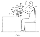
- an adjustable reader arrangement for reading encoded indicia, such as sound-encoded indicia 20, formed on an object, such as a reflective print 30 having an image 40 thereon.
- print 30 is disposed in a predetermined orientation with respect to reader arrangement 10.
- Reader arrangement 10 comprises a portable base 50 having a recess therein, such as a slot 60 formed in a top surface 65 of base 50, for reasons described in detail hereinbelow.
- a detector 70 for detecting indicia 20 has a first portion 80 having a pivot pin 90, for reasons disclosed presently.
- first portion 80 includes an extreme portion 95 thereof sized to be matingly but removably received in slot 60, so that first portion 80 is stationary with respect to base 50 when extreme portion 95 is received in slot 60.
- detector 70 includes an integrally connected second portion 100 adjustably pivotable about pivot pin 90 generally in a direction illustrated by a double headed arrow 105.
- pivot pin 90 interconnects first portion 80 and second portion 100.
- second portion 100 is preferably pivotable in an arc of approximately 120 degrees with respect to first portion 80, for reasons disclosed in detail hereinbelow. In a manner disclosed hereinbelow, second portion 100 is pivotable into alignment with indicia 20 formed on print 30 while print 30 is disposed in its predetermined orientation.
- detector 70 may comprise a light source 110 for emitting an incident light beam 113 therefrom which illuminates indicia 20 and which is to be reflected by indicia 20. Light reflected from indicia 20 defines a reflected light beam 115. Detector 70 further comprises a focusing lens 120 for focusing reflected light beam 115 onto a spectral filter 130. Filter 130 is co-axially aligned with, but spaced-apart from, lens 120 for letting through a predetermined wavelength of reflected light beam 110 and blocking all other wavelengths. Therefore, filter 130 will only allow the wavelength of reflected light beam 115 corresponding to the fluorescence or absorption wavelengths of reflected light beam 115.
- filter 130 may be coated onto lens 120, rather than being spaced-apart from lens 120, so that detector 70 is compact.
- filter 130 need not be present in the case where visible indicia are read.
- more than one filter 130 may be present in detector 70 for reading invisible as well as visible indicia 20.
- a two-dimensional array photodetector 140 such as a CCD ( C harge- C oupled D evice), is in optical communication with filter 130 for detecting reflected beam 115 passing through filter 130.
- photodetector 140 may be a CMOS device, which is a device formed by the combination of a PMOS (p-type-channel metal oxide semiconductor device) material with an NMOS (n-type-channel metal oxide semiconductor device) material.
- Detector 70 also includes image sensor electronics 150 for driving photodetector 140 data capture.
- sensor electronics 150 controls rate of data capture and converts analog charges on photodetector 140 into digital data format.
- Electrically connected to sensor electronics 150 is a memory 160.
- the purpose of memory 160 is to store the digital representation of indicia 20.
- electrically connected to memory 160 is an image processor 170.
- Image processor 170 retrieves data from memory 160 and manages the order in which the data is decoded and decompressed in a decoder 180 and a decompressor 190, respectively. Decoding and decompression of this data is preferably performed by a suitable software module, such as the "AMBE-1000 Voice Coder" available from Digital Voice Systems, Incorporated located in Northbrook, Illinois, USA.
- Digital output data from decompressor 190 is converted to an analog signal by a digital to analog converter 200.
- the analog signal is supplied to a first sound emitter 210 and/or to a second sound emitter 215 (that is, to a speaker) capable of emitting sound indicative of the indicia 20 detected by detector 70.
- a power source such as a rechargeable battery 220
- a power source such as a rechargeable battery 220
- photodetector 140 image sensor electronics 150
- memory 160 image processor 170
- decoder 180 image processor 170
- decompressor 190 digital to analog convener 200
- digital to analog converter 200 digital to analog converter 200
- reader arrangement 10 includes its own power source (that is, battery 220) disposed in detector 70.
- a battery switch 225 may be electrically connected to battery 220 for enabling battery 220.
- an electrical connection 227 and a step-down transformer 229 may be provided for electrically connecting detector 70 to an external power supply (not shown).
- print 30 includes a first side 230 having a first sound-encoded indicia 240 thereon detectable by detector 70. That is, indicia 20, when imprinted on first side 230, is defined herein to be the first sound indicia 240.
- First sound indicia 240 is preferably dye laid-down over at least a portion of image 40 and contains encoded therein a first quantity of sound information preferably regarding image 40. For example, this first quantity of sound information may be the day and date image 40 was captured.
- first sound indicia 240 may be a barcode such as UPC, EAN, Code 1, Code 39, Code 93, Code 49 or PDF-417.
- first sound indicia 240 is preferably formed of a dye substantially invisible to the naked eye in order not to interfere with aesthetic enjoyment of image 40. More specifically, indicia 240 is preferably a dye having spectral absorption in the invisible infrared region or ultraviolet region of the radiation spectrum. Such a dye is selected so that the dye does not absorb or fluoresce light in the human visible spectrum, but which is nonetheless visible to optical reading devices capable of illuminating indicia 20 with infrared light or ultraviolet light.
- the dye may be 4,4''-bis(triazin-2-ylamino)stilbene-2,2'-disulfonic acids; 2-(stilben-4-y)naphthotriasoles; or 2-(4-phenylstelben-4-yl)benzoxazoles, or other suitable dye.
- print 30 also includes a second side 250 having a second sound-encoded indicia 260 thereon detectable by detector 70. That is, indicia 20, when imprinted on second side 230, is defined herein to be the second sound indicia 260.
- Second sound indicia 260 is a dye laid-down on second side 250 and contains encoded therein a second quantity of sound information preferably regarding image 40, which second quantity of sound information may be greater than, less than, or equal to the first quantity of sound information contained on first side 230 of print 30.
- second sound indicia 260 may be imprinted over the entirety of second side 250.
- the second side indicia 260 may be obscured by the fingers of the operator as the operator 270 handles the print 30. It may be understood from the teachings herein that indicia may be surrounded by a border 275 area which does not contain the indicia. The border 275 solves the problem of obstruction by the fingers of the operator.
- Another technique to solve the hereinabove recited problem is to provide redundant information in indicia on second side 250 or first side 230.
- information contained on, for example, the second side 250 may contain portions that are redundant with other portions of information on second side 250. The advantage of this redundant information is that dispite being obscured in part by a finger, the information on the remainder of the print that is not obscured is adequate to retrieve the entire amount of data.
- second sound indicia 260 which also may be in the form of a barcode, is preferably formed of a dye visible to the naked eye. More specifically, second sound indicia 260 is a dye having spectral absorption in the visible region of the radiation spectrum. Such a dye is selected so that the dye absorbs or fluoresces light in the human visible spectrum and so that indicia 20 is visible to optical reading devices capable of illuminating indicia 20. For this purpose, the dye may be any suitably human perceivable dye well known in the art. Furthermore, presence of second sound indicia 260 assists in archival image-keeping. This is so because second sound indicia 260 may, at least in part, be identical to first sound indicia 240. This is important because in this case second sound indicia 260 can be used to replicate first sound indicia 240 should first sound indicia 240 become corrupted and unreadable. Use of recorder arrangement 10 is described hereinbelow.
- an operator 270 of reader arrangement 10 positions himself near reader arrangement 10 and manually pivots second portion 100 about pivot pin 90, so that lens 120 faces generally towards operator 270.
- operator 270 activates battery 220 by moving battery switch 225, so that detector 70 is enabled. That is, when detector 70 is enabled, the following components operate: light source 110, photodetector 140, image sensor electronics 150, memory 160, image processor 170, decoder 180, decompressor 190 and digital to analog converter 200.
- Operator 270 may then interpose print 30 between operator 270 and lens 120, such that first side 230 of print 30 faces operator 270 and second side 250 faces lens 120.
- Second indicia 260 residing on second side 250 of print 30, whereupon the light is reflected to define the previously mentioned reflected light beam 115.
- the operator may be aided in presenting the print to the reader's beam given that if the operator notices the incident light beam 113 passing around the print, it is understood that the print must be moved closer to the reader until light no longer passes around the print. Likewise, if the operator notices the incident light beam 113 passing unevenly around the print, it is understood that the print must be realigned with the beam.
- Reflected light beam 115 passes through focusing lens 120 and is focused onto a spectral filter 130 that allows a predetermined wavelength of reflected light beam 115 to pass through filter 130.
- Photodetector 140 detects the predetermined wavelength of reflected beam 115 passing trough filter 130 and produces analog charges on photodetector 130.
- Image sensor electronics 150 drives photodetector 140 data capture by controlling rate of data capture and by converting analog charges on photodetector 140 into digital data format.
- Memory 160 stores this digital representation of indicia 20.
- Processor 170 retrieves this data from memory 160 and manages the order in which the data is decoded and decompressed in decoder 180 and decompressor 190, respectively.
- Digital output data from decompressor 190 is then converted to an analog signal by digital to analog converter 200.
- the analog signal is supplied to first sound emitter 210 and/or second sound emitter 215 for emitting sound indicative of second indicia 260 detected by detector 70.
- operator 10 is able to hear sound contained in second sound-encoded indicia 260 as he simultaneously views image 40 by suitably positioning second portion 100 of detector 70.
- reader arrangement 10 is ergonomically conducive to hearing the sound-encoded information stored on second side 250 as operator 270 simultaneously views image 40 at a convenient viewing angle 275.
- Second embodiment reader arrangement 10 includes the same components as the first embodiment reader arrangement 10 described hereinabove, except that this second embodiment arrangement 10 includes a collar 280 interconnecting first portion 80 to second portion 100 of detector 70. Collar 280 allows second portion 100 to be adjustably rotatable through an angle of approximately 360 degrees about an axis 285 extending longitudinally through first portion 80, as illustrated by double-headed arrow 285.
- reader arrangement 10 has at least two degrees freedom of movement.
- a first degree freedom of movement is provided by ability of second portion 100 to pivot generally in direction of arrow 105.
- a second degree freedom of movement is provided by ability of second portion 100 to rotate generally in direction of arrow 285.
- second embodiment of reader arrangement 10 is ergonomically conducive to hearing the sound-encoded information stored on second side 250 as operator 270 views image 40 in any one of a plurality of orientations.
- a third embodiment reader arrangement 10 is there shown for reading sound-encoded indicia 20 printed onto a region 290 formed on an object, such as a calendar 300.
- base 50 includes a calendar mount (not shown) for mounting calendar 300 on top surface 65.
- Sound-encoded indicia 20 may for example be information related to month, day and date; holidays; and/or "thought of the day".
- Indicia is preferably printed on calendar 300 in invisible dye in order not to detract from appearance of calendar 300.
- indicia 20 may be printed on calendar 300 in dye visible to the naked eye, if desired.
- an advantage of the present invention is that corrupted indicia on first side 230 of print 30 can be replicated by detecting indicia on second side 250 of print 30. This is so because second sound-encoded indicia 260 may have a portion thereof identical to first sound-encoded indicia 240. Thus, even if first sound indicia 240 is corrupted or otherwise unreadable, detector 70 will read the identical sound file printed on second side 250 of print 30.
- Another advantage of the present invention is that necessarily more sound-encoded data may be stored on print 30. This is so because relative to a single side, twice as much information may be stored when both sides are completely used.
- reader arrangement 10 is ergonomically conducive to hearing the sound-encoded information stored on second side 250 as operator 270 simultaneously views image 40. This is so because second portion 100 is pivotable and rotatable to a position convenient for user 270.
- reader arrangement 10 is independent of an external power source, if desired. This is so, at least in part, because power supplied to detector 70 is by means of rechargeable battery 220 disposed in detector 70.
- Still another advantage of the present invention is that sound-encoded information appearing on a multiplicity of prints can be read less laboriously and in shorter time, when compared to prior art devices. This is so because a hand-held detector (that is, wand) need not be manually passed over second indicia 260. Rather, after second portion 100 is adjusted by user 270, indicia 20 belonging to a multiplicity of prints 30 may be read merely by quickly disposing each successive print between second portion 100 and user 270.
- a hand-held detector that is, wand
- Another advantage of the present invention is that a greater quantity of sound-encoded data can be stored on a print, so as to obviate need for time consuming printing of sound information in multiple layers. This so because area of second side 250 is large enough to retain a relatively large quantity of second sound-encoded indicia 260 (for example, approximately 3 megabytes on a 8 inch by 10 inch print).
- detector 70 may have a second spectral filter therein for filtering a second wavelength of light reflected from invisible first indicia 240.
- detector 70 is capable of detecting light of a first wavelength reflected from invisible first indicia 240 in order to read first indicia 240 and also capable of detecting light of a second wavelength reflected from visible second indicia 260 in order to read second indicia 260.
- indicia 20 may be other than sound indicia, such as indicia representative of an image.
Landscapes
- Physics & Mathematics (AREA)
- Electromagnetism (AREA)
- Engineering & Computer Science (AREA)
- Health & Medical Sciences (AREA)
- General Health & Medical Sciences (AREA)
- Toxicology (AREA)
- Artificial Intelligence (AREA)
- Computer Vision & Pattern Recognition (AREA)
- General Physics & Mathematics (AREA)
- Theoretical Computer Science (AREA)
- Image Input (AREA)
- Character Input (AREA)
Applications Claiming Priority (2)
| Application Number | Priority Date | Filing Date | Title |
|---|---|---|---|
| US09/119,882 US6561429B2 (en) | 1998-07-21 | 1998-07-21 | Adjustable reader arrangement and method of reading encoded indicia formed on an object |
| US119882 | 1998-07-21 |
Publications (2)
| Publication Number | Publication Date |
|---|---|
| EP0974923A2 true EP0974923A2 (fr) | 2000-01-26 |
| EP0974923A3 EP0974923A3 (fr) | 2003-01-02 |
Family
ID=22386978
Family Applications (1)
| Application Number | Title | Priority Date | Filing Date |
|---|---|---|---|
| EP99202241A Withdrawn EP0974923A3 (fr) | 1998-07-21 | 1999-07-09 | Dispositif lecteur ajustable et méthode de lecture d'indices codées formées sur un objet |
Country Status (3)
| Country | Link |
|---|---|
| US (1) | US6561429B2 (fr) |
| EP (1) | EP0974923A3 (fr) |
| JP (1) | JP2000057252A (fr) |
Families Citing this family (25)
| Publication number | Priority date | Publication date | Assignee | Title |
|---|---|---|---|---|
| JP4073120B2 (ja) * | 1999-06-03 | 2008-04-09 | 富士通株式会社 | 情報処理装置 |
| US6990293B2 (en) * | 2001-03-15 | 2006-01-24 | Ron Hu | Picture changer with recording and playback capability |
| US20020158129A1 (en) * | 2001-03-15 | 2002-10-31 | Ron Hu | Picture changer with recording and playback capability |
| US20030222147A1 (en) * | 2002-06-04 | 2003-12-04 | Hand Held Products, Inc. | Optical reader having a plurality of imaging modules |
| US20040059462A1 (en) * | 2002-09-20 | 2004-03-25 | Norris Michael O. | Hand held OCR apparatus and method |
| US7021542B2 (en) * | 2003-08-01 | 2006-04-04 | Symbol Technologies, Inc. | Imaging and illumination engine for an optical code reader |
| IL158048A (en) * | 2003-09-22 | 2010-12-30 | Lilach Furman | Reading device for reading labels having bi-dimensional distinguishing features |
| US7370802B2 (en) * | 2004-02-07 | 2008-05-13 | Siemens Energy & Automation, Inc. | Hand held scanner with rotating head |
| US7118039B1 (en) * | 2005-04-12 | 2006-10-10 | Kuan-Hung Sun | Bar code addressing audio playing device |
| US7516899B2 (en) * | 2006-03-06 | 2009-04-14 | V.L. Engineering, Inc. | Hand held wireless reading viewer of invisible bar codes |
| WO2008024777A2 (fr) | 2006-08-22 | 2008-02-28 | Eye Ear It, Llc. | systèmes et appareil d'expression de présentations multimédias correspondant à des supports d'impression |
| US8714441B2 (en) | 2006-08-22 | 2014-05-06 | Eye Ear It, Llc | Systems and apparatus for expressing multimedia presentations corresponding to print media |
| US20080121721A1 (en) * | 2006-11-25 | 2008-05-29 | Chun-Hsien Chen | Reflective Reading Structure For Portable Computer |
| US8267323B2 (en) * | 2007-10-26 | 2012-09-18 | Hewlett-Packard Development Company, L.P. | Printing device handle |
| US9649551B2 (en) | 2008-06-03 | 2017-05-16 | Tweedletech, Llc | Furniture and building structures comprising sensors for determining the position of one or more objects |
| US8974295B2 (en) | 2008-06-03 | 2015-03-10 | Tweedletech, Llc | Intelligent game system including intelligent foldable three-dimensional terrain |
| US8602857B2 (en) | 2008-06-03 | 2013-12-10 | Tweedletech, Llc | Intelligent board game system with visual marker based game object tracking and identification |
| WO2012033862A2 (fr) | 2010-09-09 | 2012-03-15 | Tweedletech, Llc | Jeu multidimensionnel comprenant des composants physiques et virtuels interactifs |
| WO2009149112A1 (fr) | 2008-06-03 | 2009-12-10 | Tweedletech, Llc | Système de jeu intelligent permettant d’intégrer de l’intelligence dans des jeux de société et de plateau comprenant des miniatures |
| US8186592B2 (en) * | 2009-12-07 | 2012-05-29 | Hand Held Products, Inc. | Universal stand for indicia readers |
| JP5993856B2 (ja) | 2010-09-09 | 2016-09-14 | トウィードルテック リミテッド ライアビリティ カンパニー | 動的特徴追跡を有するボードゲーム |
| US20130123009A1 (en) * | 2011-11-10 | 2013-05-16 | Tweedletech, Llc | Intelligent board game system with visual marker based object tracking and identification |
| US8991705B2 (en) | 2013-03-12 | 2015-03-31 | Symbol Technologies, Inc. | Apparatus for, and method of, electro-optically reading targets by enabling a customer to move a customer-operated accessory reader supported by a clerk-operated workstation of a checkout system |
| US12141651B2 (en) * | 2019-06-03 | 2024-11-12 | Zebra Technologies Corporation | Digital barcode reader |
| US11521001B2 (en) * | 2020-03-09 | 2022-12-06 | Toshiba Tec Kabushiki Kaisha | Radio tag reading device |
Family Cites Families (41)
| Publication number | Priority date | Publication date | Assignee | Title |
|---|---|---|---|---|
| NL7904469A (nl) | 1979-06-07 | 1980-12-09 | Philips Nv | Inrichting voor het lezen van een gedrukte kode en het daarvan omzetten in een audio-signaal. |
| JPS60222979A (ja) * | 1984-04-19 | 1985-11-07 | Toshiba Corp | 情報読取装置 |
| US4681548A (en) * | 1986-02-05 | 1987-07-21 | Lemelson Jerome H | Audio visual apparatus and method |
| WO1987006752A1 (fr) * | 1986-05-01 | 1987-11-05 | Trevor Gwilym Lloyd | Appareil d'enseignement du langage |
| US4904853A (en) | 1987-09-22 | 1990-02-27 | Kabushiki Kaisha Astex | Dual-function information-carrying sheet device |
| US4871904A (en) | 1987-12-28 | 1989-10-03 | Symbol Technologies, Inc. | Multidirectional optical scanner |
| US5448046A (en) * | 1987-12-28 | 1995-09-05 | Symbol Technologies, Inc. | Arrangement for and method of expediting commercial product transactions at a point-of-sale site |
| US5479002A (en) * | 1988-05-11 | 1995-12-26 | Symbol Technologies, Inc. | Bar code scanner with scanning beam and/or field of view adjustable about three mutually orthogonal axes |
| JPH0236825U (fr) | 1988-09-02 | 1990-03-09 | ||
| US4983818A (en) * | 1989-01-30 | 1991-01-08 | Metrologic Instruments, Inc. | Data acquisition system with laser scanner module |
| US4939356A (en) | 1989-05-02 | 1990-07-03 | Spectra-Physics, Inc. | Bar code scanner with asterisk scan pattern |
| JPH03156587A (ja) * | 1989-08-04 | 1991-07-04 | Nippondenso Co Ltd | バーコード読取装置 |
| JPH0821056B2 (ja) * | 1989-09-12 | 1996-03-04 | 日本電装株式会社 | バーコード読取装置 |
| US4968883A (en) * | 1989-10-20 | 1990-11-06 | Ncr Corporation | Apparatus and method for vertical mounting of an optical scanner |
| GB8927079D0 (en) * | 1989-11-30 | 1990-01-31 | Newtronics Sa | Coded card reader systems |
| AU643026B2 (en) * | 1990-06-15 | 1993-11-04 | Nippondenso Co. Ltd. | Information reader |
| US5260553A (en) * | 1990-09-17 | 1993-11-09 | Metrologic Instruments, Inc. | Automatic hand-supportable laser bar code symbol scanner and method of reading bar code symbols using the same |
| US5340973A (en) * | 1990-09-17 | 1994-08-23 | Metrologic Instruments, Inc. | Automatic laser scanning system and method of reading bar code symbols using same |
| US5347113A (en) * | 1991-11-04 | 1994-09-13 | Spectra-Physics Scanning Systems, Inc. | Multiple-interface selection system for computer peripherals |
| US5276472A (en) | 1991-11-19 | 1994-01-04 | Eastman Kodak Company | Photographic film still camera system with audio recording |
| US5314336A (en) * | 1992-02-07 | 1994-05-24 | Mark Diamond | Toy and method providing audio output representative of message optically sensed by the toy |
| WO1994015253A1 (fr) | 1992-12-23 | 1994-07-07 | Tsai, Irving | Dispositif et procede de production de photos immobiles et sonores sur pellicules photographiques |
| US5324927A (en) | 1993-01-08 | 1994-06-28 | Board Of Regents-Univ. Of Nebraska | Return mail piece and method of marking the same |
| US5478998A (en) | 1993-05-10 | 1995-12-26 | Symbol Technologies, Inc. | Tilting wall-mounted optical scanner |
| US5801067A (en) * | 1993-10-27 | 1998-09-01 | Ronald Shaw | Method for recording and identifying integrated circuit chips and the like |
| US5767501A (en) * | 1993-11-24 | 1998-06-16 | Metrologic Instruments, Inc. | Mass-balanced automatic hand-supportable laser projection scanner for fatigue-free omnidirectional scanning of bar code symbols |
| US5483052A (en) * | 1993-12-07 | 1996-01-09 | Smith, Iii; Herbert J. | System for reading, storing and using bar-encoded data from a coded business card or other printed material |
| JP3252877B2 (ja) * | 1994-02-08 | 2002-02-04 | 富士通株式会社 | 記憶データ確認方法及び装置 |
| US5574519A (en) | 1994-05-03 | 1996-11-12 | Eastman Kodak Company | Talking photoalbum |
| US5477044A (en) * | 1994-07-22 | 1995-12-19 | Intermec Corporation | Symbology reader with a variable orientation head |
| US5692225A (en) | 1994-08-30 | 1997-11-25 | Eastman Kodak Company | Voice recognition of recorded messages for photographic printers |
| JPH0877720A (ja) | 1994-09-01 | 1996-03-22 | Fuji Photo Film Co Ltd | 磁気情報の記録方法 |
| US5502304A (en) | 1994-12-01 | 1996-03-26 | Pitney Bowes Inc. | Bar code scanner for reading a visible ink and a luminescent invisible ink |
| JPH09141210A (ja) * | 1995-11-20 | 1997-06-03 | Lintec Corp | イメージプリンティングラベラ装置 |
| US5763865A (en) * | 1996-04-01 | 1998-06-09 | Symbol Technologies, Inc. | Reader module for reading bar code symbols when connected to or disconnected from a terminal module |
| US5979764A (en) * | 1996-07-22 | 1999-11-09 | Symbol Technologies, Inc. | Hand-held electronic apparatus with pivoting display |
| US5757468A (en) | 1996-08-29 | 1998-05-26 | Eastman Kodak Co | Method and apparatus for producing photographic prints with sound indicia thereon |
| JPH1097733A (ja) * | 1996-09-19 | 1998-04-14 | Nippon Columbia Co Ltd | 光情報記録媒体 |
| US5774752A (en) | 1996-12-26 | 1998-06-30 | Eastman Kodak Company | Processing of sound media with still image films in photofinishing labs |
| US5945656A (en) * | 1997-05-27 | 1999-08-31 | Lemelson; Jerome H. | Apparatus and method for stand-alone scanning and audio generation from printed material |
| EP1211881A1 (fr) * | 2000-12-04 | 2002-06-05 | Fuji Photo Film Co., Ltd. | Méthode et dispositif de traitement d'images |
-
1998
- 1998-07-21 US US09/119,882 patent/US6561429B2/en not_active Expired - Fee Related
-
1999
- 1999-07-09 EP EP99202241A patent/EP0974923A3/fr not_active Withdrawn
- 1999-07-21 JP JP11206102A patent/JP2000057252A/ja active Pending
Also Published As
| Publication number | Publication date |
|---|---|
| JP2000057252A (ja) | 2000-02-25 |
| US20030071127A1 (en) | 2003-04-17 |
| EP0974923A3 (fr) | 2003-01-02 |
| US6561429B2 (en) | 2003-05-13 |
Similar Documents
| Publication | Publication Date | Title |
|---|---|---|
| US6561429B2 (en) | Adjustable reader arrangement and method of reading encoded indicia formed on an object | |
| US6431452B2 (en) | Portable data collection device with variable focusing module for optic assembly | |
| US5793033A (en) | Portable data collection device with viewing assembly | |
| US5821518A (en) | Method and apparatus for a portable non-contact label imager | |
| JP2833975B2 (ja) | ドットコード | |
| US6441921B1 (en) | System and method for imprinting and reading a sound message on a greeting card | |
| JP4870815B2 (ja) | 被写体上に内在する不可視イメージを観測しながら簡易に撮影ができる装置、および、それを利用する方法 | |
| US6229964B1 (en) | Image with sound playback apparatus | |
| US6775381B1 (en) | Method and apparatus for editing and reading edited invisible encodements on media | |
| US5555105A (en) | Business card image copier | |
| CA2440755C (fr) | Changeur d'image dote d'une capacite d'enregistrement et de lecture | |
| US7490773B2 (en) | Apparatus and method for obtaining an image of an arcuate surface | |
| US20040001150A1 (en) | Imaging apparatus having automatic medium identification and method for automatically identifying a medium in an imaging apparatus | |
| JP2001526430A (ja) | スマートセンサを備えた単一チップ構造の記号読取装置 | |
| CN205959208U (zh) | 一种扫描器 | |
| HRP20030295A2 (en) | Peripheral device for acquiring biometric and personal data, particularly for preparing recognition documents | |
| JP3181866B2 (ja) | 情報再生システム | |
| CN108256367A (zh) | 用于dpm扫描仪的照明器 | |
| JP3390160B2 (ja) | 情報再生装置 | |
| JP3393045B2 (ja) | 情報記録システム及び情報記録方法 | |
| JP3564051B2 (ja) | 情報再生装置及び情報再生方法 | |
| JPH0696246A (ja) | バーコード読取装置 | |
| JPH11328303A (ja) | 情報再生装置 | |
| CA2202908C (fr) | Procede et dispositif portable de lecture sans contact d'une image sur une etiquette | |
| JPH11316808A (ja) | 情報再生装置 |
Legal Events
| Date | Code | Title | Description |
|---|---|---|---|
| PUAI | Public reference made under article 153(3) epc to a published international application that has entered the european phase |
Free format text: ORIGINAL CODE: 0009012 |
|
| AK | Designated contracting states |
Kind code of ref document: A2 Designated state(s): AT BE CH CY DE DK ES FI FR GB GR IE IT LI LU MC NL PT SE |
|
| AX | Request for extension of the european patent |
Free format text: AL;LT;LV;MK;RO;SI |
|
| PUAL | Search report despatched |
Free format text: ORIGINAL CODE: 0009013 |
|
| AK | Designated contracting states |
Kind code of ref document: A3 Designated state(s): AT BE CH CY DE DK ES FI FR GB GR IE IT LI LU MC NL PT SE |
|
| AX | Request for extension of the european patent |
Free format text: AL;LT;LV;MK;RO;SI |
|
| 17P | Request for examination filed |
Effective date: 20030528 |
|
| AKX | Designation fees paid |
Designated state(s): DE FR GB |
|
| STAA | Information on the status of an ep patent application or granted ep patent |
Free format text: STATUS: THE APPLICATION HAS BEEN WITHDRAWN |
|
| 18W | Application withdrawn |
Effective date: 20051024 |