EP0974931A1 - Verfahren und Vorrichtung zur Identifikation einer Mehrzahl von Teilbildern aus einem Eingangsbild - Google Patents
Verfahren und Vorrichtung zur Identifikation einer Mehrzahl von Teilbildern aus einem Eingangsbild Download PDFInfo
- Publication number
- EP0974931A1 EP0974931A1 EP98305917A EP98305917A EP0974931A1 EP 0974931 A1 EP0974931 A1 EP 0974931A1 EP 98305917 A EP98305917 A EP 98305917A EP 98305917 A EP98305917 A EP 98305917A EP 0974931 A1 EP0974931 A1 EP 0974931A1
- Authority
- EP
- European Patent Office
- Prior art keywords
- edge
- image
- objects
- input image
- identifying
- Prior art date
- Legal status (The legal status is an assumption and is not a legal conclusion. Google has not performed a legal analysis and makes no representation as to the accuracy of the status listed.)
- Withdrawn
Links
Images


Classifications
-
- G—PHYSICS
- G06—COMPUTING OR CALCULATING; COUNTING
- G06T—IMAGE DATA PROCESSING OR GENERATION, IN GENERAL
- G06T7/00—Image analysis
- G06T7/10—Segmentation; Edge detection
- G06T7/12—Edge-based segmentation
-
- G—PHYSICS
- G06—COMPUTING OR CALCULATING; COUNTING
- G06T—IMAGE DATA PROCESSING OR GENERATION, IN GENERAL
- G06T2207/00—Indexing scheme for image analysis or image enhancement
- G06T2207/10—Image acquisition modality
- G06T2207/10004—Still image; Photographic image
- G06T2207/10008—Still image; Photographic image from scanner, fax or copier
-
- G—PHYSICS
- G06—COMPUTING OR CALCULATING; COUNTING
- G06T—IMAGE DATA PROCESSING OR GENERATION, IN GENERAL
- G06T2207/00—Indexing scheme for image analysis or image enhancement
- G06T2207/30—Subject of image; Context of image processing
- G06T2207/30176—Document
Definitions
- This invention relates generally to an image processing technique, and more particularly to the automatic segmentation and characterization of a plurality of image objects placed on the platen of an image input device.
- US-A-5,485,568 to Venable et al. discloses a method and apparatus for representing a complex color raster image as a collection of objects in a structured image format - a hierarchical, device-independent format.
- a structured image document generated using the techniques described by Venable, is a representation of data that may be rendered into a raster image.
- the data includes simple raster images as well as a hierarchical collection of subobjects and raster processing operations.
- the possible data types for objects in the structured image include a raster image, text, graphics, image processing description, and files containing multiple image representations
- Venable et al. teach the use of structured images to manage prepress workflow. An operation such as gang scanning is described as a means for capturing several photographs roughly aligned on a scanner platen.
- a method for processing a digital input image to characterize a plurality of objects therein comprising:
- an image processing apparatus including a programmable computer capable of receiving a digitized input image, the computer including a frame buffer memory for storing the input image and program memory for the storage of code suitable for causing the computer to execute image processing operations including:
- the present invention is directed to a software-based system developed to accomplish the automatic determination of independent regions or segments within a scanned image.
- the present invention combines a number of graphics and image processing techniques into an automated, user-friendly application for productivity enhancement.
- the application can enhance productivity by decreasing the time required for scanning multiple images, by automating corrections for alignment of multiple images, and even automatically placing multiple images in a document template.
- the present invention accomplishes these objectives by:
- One aspect of the invention deals with a basic problem in digital image processing, that of identifying plural objects within a digitized image. This aspect is further based on the discovery of image processing techniques that alleviate this problem.
- the techniques described herein enable a user to expediently scan a plurality of documents in a single scanning operation, and then automatically separate those documents by recognizing them as independent objects within the digitized image.
- Another aspect of the present invention allows for the automatic creation of a structured image representation of the digitized image so that the image objects may be easily extracted and further processed, independently.
- the techniques described above are advantageous because they improve the efficiency of a scanning process, allowing multiple original documents to be scanned at one time.
- the techniques allow for the automatic characterizing physical attributes (e.g., location, shape and orientation) of the objects without user intervention.
- data refers herein to physical signals that indicate or include information.
- an item of data can indicate one of a number of possible alternatives, the item of data has one of a number of "values.”
- a binary item of data also referred to as a "bit”
- bit has one of two values, interchangeably referred to as "1" and “0” or “ON” and “OFF” or “high” and “low”.
- a bit is an "inverse" of another bit if the two bits have different values.
- An N-bit item of data has one of 2N values.
- a "multi-bit" item of data is an item of data that includes more than one bit.
- Memory circuitry or “memory” is any circuitry that can store data, and may include local and remote memory and input/output devices. Examples include semiconductor ROMs, RAMs, and storage medium access devices with data storage media that they can access.
- a “memory cell” is memory circuitry that can store a single unit of data, such as a bit or other n-ary digit or an analog value.
- a signal "indicates” or “selects” one of a set of alternatives if the signal causes the indicated one of the set of alternatives to occur.
- a signal can indicate one bit set in a sequence of bit sets to be used in an operation, in which case the signal causes the indicated bit set to be used in the operation.
- An "image” is a pattern of physical light.
- An image may include characters, words, and text as well as other features such as graphics.
- a text may be included in a set of one or more images, such as in images of the pages of a document.
- An image may be processed so as to identify specific "objects" within the image, each of which is itself an image.
- a object may be of any size and shape and has physical attributes or characteristics including, but not limited, to position, shape and orientation.
- An item of data "defines" an image when the item of data includes sufficient information to produce the image.
- a two-dimensional array can define all or any part of an image, with each item of data in the array providing a value indicating the color of a respective location of the image.
- An item of data "defines" an image set when the item of data includes sufficient information to produce all the images in the set.
- Each location in an image may be called a "pixel".
- each value indicating the color of a location may be called a "pixel value”.
- Each pixel value is a bit in a "binary form” of an image, a gray scale value in a “gray scale form” of an image, or a set of color space coordinates in a "color coordinate form” of an image, the binary form, gray scale form, and color coordinate form each being a two-dimensional array defining an image.
- An operation performs "image processing" when it operates on an item of data that relates to part of an image.
- Pixels are "neighbors” or “neighboring” within an image when there are no other pixels between them and they meet an appropriate criterion for neighboring. If the pixels are rectangular and appear in rows and columns within a two-dimensional image, each pixel may have 4 or 8 neighboring pixels, depending on the criterion used.
- edge occurs in an image when two neighboring pixels have sufficiently different pixel values according to an appropriate criterion for the occurrence of an edge between them.
- edge pixel or “boundary pixel” may be applied to one or both of two neighboring pixels between which an edge occurs.
- An “image characteristic” or “characteristic” is a measurable attribute of an image.
- An operation can “measure” a characteristic by producing data indicating the characteristic using data defining an image.
- a characteristic is measured “for an image” if the characteristic is measured in a manner that is likely to produce approximately the same result each time it occurs.
- a "version" of a first image is a second image produced using an item of data defining the first image.
- the second image may be identical to the first image, or it may be modified by loss of resolution, by changing the data defining the first image, or by other processes that result in modifying pixel values of the first image.
- An “image input device” is a device that can receive an image and provide an item of data defining a version of the image.
- a “scanner” is an image input device that receives an image by a scanning operation, such as by scanning a document.
- An “image output device” is a device that can receive an item of data defining an image and provide or render the image as output.
- a “display” is an image output device that provides the output image in human viewable form
- a “printer” is an image output device that renders the output image in a human viewable, hard copy form.
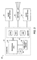
- System 20 includes a computer 22 capable of receiving digital data representing an image of an original document 24 placed upon a platen of scanner 26.
- Computer 22 initially stores the digital input data from scanner 26 in memory 52 (e.g., RAM or magnetic disk storage) where the image may subsequently be accessed.
- memory 52 may also include program memory for the storage of object code suitable for directing the processor to execute image processing operations in accordance with the invention described herein.
- Computer 22 has associated therewith a user interface (U/I) 28 including one or more user input devices 30, such as a keyboard, a keypad, a mouse, trackball, stylus or equivalent pointing device, etc.
- U/I user interface
- system 20 is an image output device such as printer 34 which may include a laser-driven, xerographic printing engine as found in a number of commercially available printers.
- system 20 is employed to process the digital image data received as input from a scanner 26, utilizing image processing software running in processor 50, so as to produce an output file that may be rendered by printer 34, stored in memory 50, and/or transmitted to another device via network 40.
- the document placed upon the scanner platen may include a plurality of photographs or other objects represented by marks on a substrate surface, or that such objects may be scanned by a single scanning operation.
- a particular embodiment to which the following description will be directed is a single scanned image representative of several separate photographs laid side by side on the platen of scanner 26, but not touching or overlapping.
- the present invention automatically identifies at least the position, shape and orientation angle of each photograph.
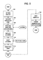
- the process carried out by computer 22 during the processing of the input image includes three general steps. First, at step 100 the objects within the image are located and boundaries of the object are generally identified. Once the objects are located, the shape of the objects is modeled at step 200. Having located the objects and modeled their shape, a structured image representing the image and objects therein can be created as represented by step 300.
- the structured image preferably includes data representing not only the image data itself, but data representing the location, shape or orientation of each object, or some combination thereof.
- the output may be a page description language format or equivalents formats suitable for storing the image information in a retrievable form.
- the scanned input image (or a lower resolution version thereof) is loaded into a memory frame buffer (RAM) where it is analyzed in accordance with the previously described steps.
- RAM memory frame buffer
- the object location step 100 is performed by first identifying the background region of the input image 102, characterizing the background region 104, and then using the characteristic of the background region as a seed, identifying all the pixels representing the background region with an adaptive seed fill algorithm 106.
- Background pixels are pixels not associated with any objects, or more simply, they are pixels representative of those regions lying outside of the objects, the values of which are controlled by the "background" against which the objects are placed during scanning (e.g., the underside of the platen cover).
- One embodiment employs the average color of a small region in the upper left-hand corner of the scanned image as an initial estimate of the background color.
- other sampling operations may be employed to determine the background color as described, for example, in US-A-5,282,091 for a Programmable Apparatus for Determining Document Background Level by Farrell.
- an adaptive algorithm is preferably applied to control the background color and to accurately identify the objects.
- An example of a seed fill algorithm suitable for use in the present invention is described in Graphics Gems I, A. Glassner Ed., Academic Press, pp. 275-277, 1990, hereby incorporated by reference.
- An adaptive algorithm is required because the background pixels may have significant color variation resulting from a variation in illumination over the platen area.
- the adaptive seed fill algorithm is applied to the scanned color image data using an initial seed point characterized by the background, for example, the upper-left corner of the image.
- the adaptive seed fill algorithm fills a binary frame buffer with a mask indicating all contiguous pixels identified as background pixels.
- a pixel is considered to be a background pixel if its color falls within a small distance ⁇ of the current average background pixel value.
- the value of ⁇ is fixed and empirically determined in one embodiment.
- the test conducted at step 112 is: if d ⁇ , then pixel P is a background pixel, else pixel P is a foreground pixel.
- the average background color is adaptively modified at step 114 by taking the average value of the last N pixels that have been classified as background.
- AdAvg' (N*AdAvg-AdAvg+LastVal)/N, where AdAvg' is the modified average, AdAvg is the previous adaptive average, LastVal is the value of the last pixel identified as background, and N is the averaging window.
- AdAvg' (N*AdAvg-AdAvg+LastVal)/N, where AdAvg' is the modified average, AdAvg is the previous adaptive average, LastVal is the value of the last pixel identified as
- the process at step 120 is executed to smooth noisy edges in the background mask using morphological filtering. More specifically, a morphological closure filter is preferably applied to the background mask to eliminate single pixel noise and to smooth object edges. Subsequently, contiguous foreground regions are located, step 122, thereby identifying the objects.
- Objects are identified by scanning the background mask generated by the adaptive seed fill operation (step 106). Starting with the upper left hand pixel, the mask is searched in a scan line fashion for a pixel not classified in the mask as a background pixel - thus identifying pixels associated with a foreground object. The use of the seed fill algorithm for identifying the background assures that foreground objects are closed.
- the boundary of an object is identified by tracing its edge.
- the boundary of the foreground object is traced using a simple 8-connected edge traversal which provides an ordered-set of points tracing the edge of the object.
- Such an edge traversal operation employs a contour tracing operation to generate a chain code in a manner similar to word or character based recognition systems.
- An 8-connected process is described, for example, by R. Bozinovic et al. in "Off-Line Cursive Script Word Recognition", IEEE Transactions on Pattern Analysis and Machine Intelligence, Vol. 11, No. 1 (January 1989).
- the edge is traced, all pixels associated with the object in the mask are marked as background so they will not be processed a second time, the object is added to the foreground object list and then the scanning of step 122 is continued as indicated by test step 126.
- a review of the identified objects may be completed as represented by step 130.
- the scanned image may contain undesirable foreground objects; such objects can be eliminated from the object list at this step.
- the review of the object list may simply eliminate small objects as unlikely images. For example, in a scan of a yearbook page each image has associated with it a text caption that is not to be classified as image data. Such captions consist of many, small perimeter objects, so that by measuring the perimeter length of the traced edges, it is possible to eliminate objects having a perimeter smaller than a specified length, where the threshold length may be predetermined empirically.
- step 200 is to model the shape of the object.
- the result or output from step 100 is preferably a set of edge traces, in the form of linked lists, that identify bounding pixels about each object within the scanned image. These traces can be used to extract each object, but orientation is not yet determined. To improve the quality of the object extraction, the object traces are fitted to a model shape. Orientation information, etc., may then be extracted from the fitted parameters. In the described embodiment the object traces are fit to a rectangular model, however, other shapes are possible.
- One method of fitting the edge traces to a rectangular shape is a least-squares approach to fit to a rectangle.
- the edge trace is first decomposed into four sets of points, each corresponding to one of the four sides of the rectangular object.
- the decomposition into four sets of points can be accomplished in several ways as described below.
- the first method has two principal parts, (a) categorizing the edge points into a set of bins associated with a single line, and (b) performing recognition on the bins for rotated shapes.
- step 204 calculates the slope at each point along the edge trace.
- Step 204 preferably accomplishes the slope angle calculation by performing a linear regression on a small window of neighboring edge points. For example, 2 points lying on either side of the edge point for which the slope is being determined. The angle of the line passing through the center of each point is determined using linear regression in a small window centered on each point.
- each regression requires 4 additions per point in the window, plus 2 subtractions, 2 multiplications, and an arctangent calculation, however, the regression algorithm may be further optimized to remove most of the addition operations.
- a sample of the edge pixels are employed for slope angle calculations and sorting, thereby reducing the number of calculations necessary to categorize the edge pixels.
- the process constructs a list of slope categories or bins.
- the slope categories are constructed for each edge point by calculating the magnitude of the difference in the slope angle between the current point along the edge (e.g., point B in Figure 8) and the preceding point (e.g., point A in Figure 8). If the difference is less than the value TOLERANCE (determined empirically to be ⁇ 5 degrees in one embodiment), then the point is assigned to the same slope category as the preceding point, otherwise a new slope category is created and the point is assigned to it. Referring to Figure 8, the above-described process would assign points A, B and C to a first slope category, points D, E, F, G and H to a second slope category and points I, J ... to yet another slope category. Finally, if the slope category for the last edge point has approximately the same slope angle as the first slope category, then all points within the first and last slope categories are joined together into a single category.
- the slope categories are established at step 206, and stored in a data structure, they are then sorted at step 208 and ordered according to the number of edge points assigned to each category. For rectangular objects, the top four slope categories, those containing the most edge points, should correspond to points along the four edges of the rectangle. The top slope categories are then selected at step 210. It will be appreciated that one would use the top six categories for hexagonal objects, and similarly the top three categories for triangular objects, etc.
- steps 208 and 210 may be replaced by a step that processes the slope angle categories or bins by simple, or even statistical elimination, wherein those categories with few entries are removed. For example, an empirically determined threshold of 5 pixels may be applied so that only bins having more than 5 pixels with a common angle are kept. Subsequently, an average angle for a category may be determined using simple linear regression of all the points assigned to a particular category. With the average angle determined, a further refinement of the categories would be possible, combining those categories having substantially common angles. In particular, each category is checked and if adjacent categories are substantially collinear, the categories are joined. Thus each of the remaining bins or categories represents a set of collinear points lying along an edge.
- the edge points assigned to each of the remaining slope angle categories represent the edge trace decomposed into the four sides of the rectangle. It will be appreciated that this alternative is broadly directed to the process of "filtering” or refining the categories to identify those representing the actual edge of the objects. Accordingly, equivalent methods of accomplishing the refinement of the categories are contemplated.
- This first method of characterizing the object boundaries is computationally intensive due to the measurement of the average slope at each edge point.
- the edge trace may be sampled to reduce the total number of points that must be processed and categorized.
- step 252 calculates the center of mass of the object.
- a straightforward approach would be averaging the (x,y) coordinates of the edge points.
- the edge point closest to the center of mass would be located at step 254. The closest point will be the approximate center of the long side of the rectangle.
- the angle ⁇ from the center-of-mass (CofM) to the center point (L a /2) is the approximate rotation angle ( ⁇ ) of the rectangle.
- step 256 determines the approximate length of the minor axis of the rectangle at step 258.
- the distance from the center-of-mass to the average position of all edge points that lie in the angular range ⁇ - ⁇ A to ⁇ + ⁇ A is determined. This distance is an approximate measure of one-half the minor axis length L b of the rectangle.
- ⁇ A is an empirically determined value on the order of approximately 5 degrees.
- Step 260 approximates the length of the major axis (L a ) in much the same manner.
- the distance from the center-of-mass to the average position ( ⁇ +90)+ ⁇ A is an approximate measure of one-half the length of the major axis L a of the rectangle.
- step 264 calculates an angular range (as measured with respect to the center-of-mass) for each side of the rectangle that encompasses only those edge points associated with that side:
- step 266 finds all the edge points that lie within each of the four angular ranges (relative to the center-of-mass) determined above, thereby identifying the edge points corresponding to each side of the rectangle. It will be appreciated that this technique is less sensitive to edge-noise than the first method described above.
- Yet another alternative method for fitting the edge traces to a shape is a method employing binary moments for fast image bounding.
- the image is rendered in a binary bitmap form where each pixel value is a 0 or 1 indicating background or non-background regions.
- the alternative embodiment depicted in Figure 7 employs second-order binary moments to fit a shape (e.g., rectangle) to the object.
- step 100 the object edges are located and recorded as previously described, thereby providing as an input a linked list of boundary or edge pixels referred to as an edge trace, step 290.
- the second order moments are calculated (step 292) in an efficient manner using the equation: where p(i,j) is the image pixel value at image coordinates (i,j) and p 1 ( i ) is the 1 th order moment of the i th scan line. (i,j) and p 1 ( i ) is the 1 th order moment of the scan line. Because the object boundary pixels are previously determined, the process can be simplified and the rightmost and left-most boundary pixels for a particular scanline are used for the 1st order (absolute) moment calculations.
- the 2nd order moments are employed to characterize an ellipse and from the ellipse the bounding box about the object, step 294.
- the center of the ellipse (x, y), the lengths of each axis (a and b) and the rotation angle ( ⁇ ) are determined.
- the bounding box for the rectangular object is determined as a rectangle centered at (x,y) with sides of length 2a and 2b, rotated by an angle ⁇ . While this renders a bounding box slightly larger than the object, this is done so as to provide a safety margin for the calculation, and to avoid cropping a portion of the object.
- the rectangle would be characterized with sides of length 2 ⁇ a and 2 ⁇ b, where ⁇ is set equal to 3 /2 or a slightly smaller value to accomplish edge trimming or cropping (e.g., on the order of one or more pixels).
- a structured image is created as described, for example, in US-A-5,485,568 to Venable et al.
- the structured image consists of one "child" structured image for each object detected using one of the methods described above.
- the structured image definition contains attributes that specify which rectangle of the scanned image contains the object data, and also the rotation angle required to correct for any orientation skew.
- Figure 9 is an example of a structured image created in accordance with the previously described processes, the structured image containing a pair of rectangular-shaped image objects.
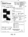
- Figure 10 illustrates a user interface 400 that may be employed with various aspects of the previously described object shape recognition method to provide an intelligent or "smart" platen or scanning system.
- the smart scanning system represented by Figure 10 preferably provides a means by which a user can interface with a digitizing scanner to efficiently obtain digitized representations of objects placed on platen 24 of a scanner.
- a user may place a number of photographs on the scanner platen. Once placed, the user may then select an operation from region 410 of Figure 10 to cause the computer system 22 to initiate scanning by scanner 26.
- system 20 scans the objects placed on platen 24 and temporarily stores the data in the file using the details reflected in region 420 of the user interface screen. For example, the various image objects (A, B, C and D) may be found within an image as illustrated in Figure 11. Once the image is scanned, it is analyzed as described above to identify the image objects.
- the image objects may then be manipulated by the smart scanning system to automatically orient and position the images, for example they may be automatically placed in a prespecified template and rendered, such as the representation depicted in region 430 of the user interface. It will be appreciated that a user may also be given additional edit capability with respect to the template, for example to add captions to the objects, or to include titles 432 and subtitles 434 as illustrated. Input for such text-based editing would be accomplished via the user interface options depicted in region 440.
- image editing capabilities as illustrated in region 450 of the user interface. Having identified each of the objects within the image, it is possible to isolate the objects, create separate images therefrom, and to then individually process the images. Thus the individual image objects automatically placed within the template of region 430 may be individually selected, manipulated, scaled (button 452), rotated (button 454) or cropped (button 456). It will be appreciated that the scaling, rotation and cropping operations are in addition to those which are preferably automatically applied by the system as the result of the previously described object recognition methods.
- the image scaling button illustrated with cross-hatching to depict selection, will allow the user to move a cursor (not shown) to select an object (e.g., image object D) and then to drag a side or corner of the object so as to scale the image object.
- control points such as those illustrated about the boundary of image object D (436) may be employed in a manner well-known to those who design user interfaces.
- a predefined template may be used to automatically "place" image objects in relative positions on a document or page thereof.
- templates may be in the form of a structured image definition, so that the template can be used to specify a different layout for the structured image to be generated.
- a family seeking to put its photographs in a "digital photo album” may be able to create a template describing a page similar to that shown in region 430 of the user interface. The template would then be used to automatically organize individual images or plural objects within a larger document image.
- the output would be a structured image output format as described by Venable et al. in US-A-5,485,568.
- An important characteristic of structured images is the ability to store image processing operations in their description. This means that the structured image can contain image processing operations other than simple object deskewing attributes. For example, automatic image enhancement operations may be included within the structured image such that the objects identified can be individually enhanced.
- the user may save the image by selecting the "Save Edited Image” button 460. More importantly, a user may then print or otherwise distribute the composed page(s).
- the acquisition of images, and the printing and distribution of the composed pages can be accomplished via networks or on a walk-up digital copier.
- a user may have photographs automatically scanned by a film processor, and a digitized stamp sheet sent to the user via a network.
- the stampsheet being in a structured image format could then be processed using the smart scanning system to produce pages of a digital photo album with one or more objects on each page.
- the present invention is a method and apparatus for processing a digital input image to characterize a plurality of objects therein.
- the technique includes: identifying at least one object within the input image by characterization of background and foreground pixels; modeling a shape representing boundaries of the object using one of two general methods; and creating a description to characterize the object, the description including not only shape and location of the object, but object rotation or skew information as well.
Landscapes
- Engineering & Computer Science (AREA)
- Computer Vision & Pattern Recognition (AREA)
- Physics & Mathematics (AREA)
- General Physics & Mathematics (AREA)
- Theoretical Computer Science (AREA)
- Image Analysis (AREA)
Priority Applications (1)
| Application Number | Priority Date | Filing Date | Title |
|---|---|---|---|
| EP98305917A EP0974931A1 (de) | 1998-07-24 | 1998-07-24 | Verfahren und Vorrichtung zur Identifikation einer Mehrzahl von Teilbildern aus einem Eingangsbild |
Applications Claiming Priority (1)
| Application Number | Priority Date | Filing Date | Title |
|---|---|---|---|
| EP98305917A EP0974931A1 (de) | 1998-07-24 | 1998-07-24 | Verfahren und Vorrichtung zur Identifikation einer Mehrzahl von Teilbildern aus einem Eingangsbild |
Publications (1)
| Publication Number | Publication Date |
|---|---|
| EP0974931A1 true EP0974931A1 (de) | 2000-01-26 |
Family
ID=8234966
Family Applications (1)
| Application Number | Title | Priority Date | Filing Date |
|---|---|---|---|
| EP98305917A Withdrawn EP0974931A1 (de) | 1998-07-24 | 1998-07-24 | Verfahren und Vorrichtung zur Identifikation einer Mehrzahl von Teilbildern aus einem Eingangsbild |
Country Status (1)
| Country | Link |
|---|---|
| EP (1) | EP0974931A1 (de) |
Cited By (3)
| Publication number | Priority date | Publication date | Assignee | Title |
|---|---|---|---|---|
| EP1470784A3 (de) * | 2003-04-21 | 2004-11-17 | Aloka Co., Ltd. | Ultraschalldiagnosegerät |
| EP2126720A4 (de) * | 2007-01-24 | 2013-03-27 | Bluebeam Software Inc | Verfahren für den abgleich eines geänderten dokuments und eines originaldokuments für vergleich und hervorhebung von unterschieden |
| CN112258558A (zh) * | 2020-10-23 | 2021-01-22 | 复旦大学 | 基于多尺度孪生网络的目标追踪方法、电子设备及介质 |
Citations (3)
| Publication number | Priority date | Publication date | Assignee | Title |
|---|---|---|---|---|
| EP0505077A2 (de) * | 1991-03-20 | 1992-09-23 | Hughes Aircraft Company | Bildortungszurückstellung geradliniger Objekte |
| EP0506327A2 (de) * | 1991-03-28 | 1992-09-30 | Texas Instruments Incorporated | System und Verfahren zur Einordnung und Gewinnung hervorstehender Konturen für Zielerkennung |
| EP0883287A1 (de) * | 1997-06-02 | 1998-12-09 | Primax Electronics Ltd | Bildverarbeitungssystem mit automatischen Bildtrennungs- und Bildausrichtungsfunktionen |
-
1998
- 1998-07-24 EP EP98305917A patent/EP0974931A1/de not_active Withdrawn
Patent Citations (3)
| Publication number | Priority date | Publication date | Assignee | Title |
|---|---|---|---|---|
| EP0505077A2 (de) * | 1991-03-20 | 1992-09-23 | Hughes Aircraft Company | Bildortungszurückstellung geradliniger Objekte |
| EP0506327A2 (de) * | 1991-03-28 | 1992-09-30 | Texas Instruments Incorporated | System und Verfahren zur Einordnung und Gewinnung hervorstehender Konturen für Zielerkennung |
| EP0883287A1 (de) * | 1997-06-02 | 1998-12-09 | Primax Electronics Ltd | Bildverarbeitungssystem mit automatischen Bildtrennungs- und Bildausrichtungsfunktionen |
Cited By (5)
| Publication number | Priority date | Publication date | Assignee | Title |
|---|---|---|---|---|
| EP1470784A3 (de) * | 2003-04-21 | 2004-11-17 | Aloka Co., Ltd. | Ultraschalldiagnosegerät |
| US7604597B2 (en) | 2003-04-21 | 2009-10-20 | Aloka Co., Ltd. | Ultrasonic diagnostic apparatus |
| EP2126720A4 (de) * | 2007-01-24 | 2013-03-27 | Bluebeam Software Inc | Verfahren für den abgleich eines geänderten dokuments und eines originaldokuments für vergleich und hervorhebung von unterschieden |
| CN112258558A (zh) * | 2020-10-23 | 2021-01-22 | 复旦大学 | 基于多尺度孪生网络的目标追踪方法、电子设备及介质 |
| CN112258558B (zh) * | 2020-10-23 | 2022-11-04 | 复旦大学 | 基于多尺度孪生网络的超声颈动脉斑块视频追踪方法 |
Similar Documents
| Publication | Publication Date | Title |
|---|---|---|
| US6738154B1 (en) | Locating the position and orientation of multiple objects with a smart platen | |
| US6839466B2 (en) | Detecting overlapping images in an automatic image segmentation device with the presence of severe bleeding | |
| US5892854A (en) | Automatic image registration using binary moments | |
| EP0660256B1 (de) | Verfahren und Gerät zur Auswahl von Text und/oder Non-Text-Blöcken in einem gespeicherten Dokument | |
| JP4065460B2 (ja) | 画像処理方法及び装置 | |
| US7697776B2 (en) | Model-based dewarping method and apparatus | |
| JP3792747B2 (ja) | 文字認識装置及び方法 | |
| US7016536B1 (en) | Method and apparatus for automatic cleaning and enhancing of scanned documents | |
| US6574375B1 (en) | Method for detecting inverted text images on a digital scanning device | |
| JP3748164B2 (ja) | パターン抽出装置 | |
| EP1403813B1 (de) | Bildverarbeitungsverfahren, -vorrichtung und -programm zum Behandeln invertierter Buchstaben | |
| US7567708B2 (en) | Apparatus and method for image processing | |
| JP3696920B2 (ja) | ドキュメント格納装置及び方法 | |
| US6704456B1 (en) | Automatic image segmentation in the presence of severe background bleeding | |
| JP3727974B2 (ja) | 画像処理装置及び方法 | |
| EP1017011A2 (de) | Blockselektion von Tabellenmerkmalen | |
| EP0975146B1 (de) | Bestimmung der Lage und Orientierung einer Vielzahl von Objekten mittels einer intelligenten Bildeingangsplatte | |
| EP0974931A1 (de) | Verfahren und Vorrichtung zur Identifikation einer Mehrzahl von Teilbildern aus einem Eingangsbild | |
| JP4001446B2 (ja) | 画像背景色特定のための方法、装置及びコンピュータ読み取り可能な記録媒体 | |
| JPH10222688A (ja) | 画像処理方法 | |
| Konya | Adaptive methods for robust document image understanding | |
| JPH04105186A (ja) | 自動文書入力装置 | |
| JP2004032537A (ja) | 画像処理方法及び画像処理装置 |
Legal Events
| Date | Code | Title | Description |
|---|---|---|---|
| PUAI | Public reference made under article 153(3) epc to a published international application that has entered the european phase |
Free format text: ORIGINAL CODE: 0009012 |
|
| AK | Designated contracting states |
Kind code of ref document: A1 Designated state(s): AT BE CH CY DE DK ES FI FR GB GR IE IT LI LU MC NL PT SE |
|
| AX | Request for extension of the european patent |
Free format text: AL;LT;LV;MK;RO;SI |
|
| STAA | Information on the status of an ep patent application or granted ep patent |
Free format text: STATUS: THE APPLICATION HAS BEEN WITHDRAWN |
|
| 18W | Application withdrawn |
Withdrawal date: 20000309 |