EP0975064A2 - Connecteur électrique - Google Patents
Connecteur électrique Download PDFInfo
- Publication number
- EP0975064A2 EP0975064A2 EP99114542A EP99114542A EP0975064A2 EP 0975064 A2 EP0975064 A2 EP 0975064A2 EP 99114542 A EP99114542 A EP 99114542A EP 99114542 A EP99114542 A EP 99114542A EP 0975064 A2 EP0975064 A2 EP 0975064A2
- Authority
- EP
- European Patent Office
- Prior art keywords
- length
- electrical connector
- connector body
- latch
- connector
- Prior art date
- Legal status (The legal status is an assumption and is not a legal conclusion. Google has not performed a legal analysis and makes no representation as to the accuracy of the status listed.)
- Withdrawn
Links
Images

Classifications
-
- H—ELECTRICITY
- H01—ELECTRIC ELEMENTS
- H01R—ELECTRICALLY-CONDUCTIVE CONNECTIONS; STRUCTURAL ASSOCIATIONS OF A PLURALITY OF MUTUALLY-INSULATED ELECTRICAL CONNECTING ELEMENTS; COUPLING DEVICES; CURRENT COLLECTORS
- H01R13/00—Details of coupling devices of the kinds covered by groups H01R12/70 or H01R24/00 - H01R33/00
- H01R13/648—Protective earth or shield arrangements on coupling devices, e.g. anti-static shielding
- H01R13/658—High frequency shielding arrangements, e.g. against EMI [Electro-Magnetic Interference] or EMP [Electro-Magnetic Pulse]
- H01R13/6581—Shield structure
- H01R13/6582—Shield structure with resilient means for engaging mating connector
- H01R13/6583—Shield structure with resilient means for engaging mating connector with separate conductive resilient members between mating shield members
-
- H—ELECTRICITY
- H01—ELECTRIC ELEMENTS
- H01R—ELECTRICALLY-CONDUCTIVE CONNECTIONS; STRUCTURAL ASSOCIATIONS OF A PLURALITY OF MUTUALLY-INSULATED ELECTRICAL CONNECTING ELEMENTS; COUPLING DEVICES; CURRENT COLLECTORS
- H01R13/00—Details of coupling devices of the kinds covered by groups H01R12/70 or H01R24/00 - H01R33/00
- H01R13/62—Means for facilitating engagement or disengagement of coupling parts or for holding them in engagement
- H01R13/629—Additional means for facilitating engagement or disengagement of coupling parts, e.g. aligning or guiding means, levers, gas pressure electrical locking indicators, manufacturing tolerances
- H01R13/633—Additional means for facilitating engagement or disengagement of coupling parts, e.g. aligning or guiding means, levers, gas pressure electrical locking indicators, manufacturing tolerances for disengagement only
- H01R13/635—Additional means for facilitating engagement or disengagement of coupling parts, e.g. aligning or guiding means, levers, gas pressure electrical locking indicators, manufacturing tolerances for disengagement only by mechanical pressure, e.g. spring force
-
- H—ELECTRICITY
- H01—ELECTRIC ELEMENTS
- H01R—ELECTRICALLY-CONDUCTIVE CONNECTIONS; STRUCTURAL ASSOCIATIONS OF A PLURALITY OF MUTUALLY-INSULATED ELECTRICAL CONNECTING ELEMENTS; COUPLING DEVICES; CURRENT COLLECTORS
- H01R13/00—Details of coupling devices of the kinds covered by groups H01R12/70 or H01R24/00 - H01R33/00
- H01R13/646—Details of coupling devices of the kinds covered by groups H01R12/70 or H01R24/00 - H01R33/00 specially adapted for high-frequency, e.g. structures providing an impedance match or phase match
-
- H—ELECTRICITY
- H01—ELECTRIC ELEMENTS
- H01R—ELECTRICALLY-CONDUCTIVE CONNECTIONS; STRUCTURAL ASSOCIATIONS OF A PLURALITY OF MUTUALLY-INSULATED ELECTRICAL CONNECTING ELEMENTS; COUPLING DEVICES; CURRENT COLLECTORS
- H01R13/00—Details of coupling devices of the kinds covered by groups H01R12/70 or H01R24/00 - H01R33/00
- H01R13/62—Means for facilitating engagement or disengagement of coupling parts or for holding them in engagement
- H01R13/627—Snap or like fastening
- H01R13/6271—Latching means integral with the housing
-
- H—ELECTRICITY
- H01—ELECTRIC ELEMENTS
- H01R—ELECTRICALLY-CONDUCTIVE CONNECTIONS; STRUCTURAL ASSOCIATIONS OF A PLURALITY OF MUTUALLY-INSULATED ELECTRICAL CONNECTING ELEMENTS; COUPLING DEVICES; CURRENT COLLECTORS
- H01R13/00—Details of coupling devices of the kinds covered by groups H01R12/70 or H01R24/00 - H01R33/00
- H01R13/62—Means for facilitating engagement or disengagement of coupling parts or for holding them in engagement
- H01R13/639—Additional means for holding or locking coupling parts together, after engagement, e.g. separate keylock, retainer strap
Definitions
- the present invention relates to an electrical connector. More particularly, the present invention relates to an electrical connector for use with, for example, an antenna connector.
- Typical electrical connectors such as, for example those used with an antenna connector for an antenna cable such as that used in the automobile industry for radios include a male connector body generally in the form of a plug and a female connector body generally in the form of a ferrule which forms a socket. In use, the male connector body is plugged into the female connector body to effect a mechanical and electrical connection between the two.
- an antenna cable in the form of a coaxial cable is electrically and mechanically attached to one of the connectors such as the male connector, and the other connector, such as the female connector, is electrically and mechanically attached to a circuit such as a circuit on a printed circuit board.
- Yet another object of the present invention is to provide an electrical connector which prevents inadvertent disconnection thereof.
- Another object of the present invention is to provide an electrical connector for use as an antenna connector.
- an electrical connector which comprises a first connector body and a second connector body which may be connected together.
- the first connector body extends in a first direction of a first longitudinal axis from a first end to a second end and comprises a first contact and at least one first locking member.
- the second connector body extends in a second direction of a second longitudinal axis from one end to another end and comprises a second contact and at least one second locking member.
- the second locking member is structured and arranged for engagement with the first locking member in a connected mode and disengagement from the first locking member in a disconnected mode.
- An elastic member is provided which is structured and arranged for (a) engagement with and compression between the first connector body and the second connector body in the connected mode and (b) decompression in the disconnected mode.
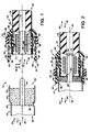
- Figs. 1 and 2 depict one embodiment of the electrical connector of the present invention.
- the electrical connector of Figs. 1 and 2 may be for use as an antenna connector.
- Figs. 1 and 2 depict an electrical connector 10 which comprises a first connector body 12 and a second connector body 14.
- the first connector body 12 extends in the direction 16, 16' of a first longitudinal axis 18 from a first end 20 to a second end 22.
- the second connector body 14 extends in the direction 24, 24' of a second longitudinal axis 26 from one end 28 to another end 30.
- axes 18 and 26 will be coincident as depicted in Fig. 2.
- the first connector body 12 and the second connector body 14 are each generally cylindrical.
- the first connector body 12 comprises a first contact 32, illustrated as a female contact formed by a ferrule in a conventional manner
- the second connector body 14 comprises a mating second contact 34, illustrated as a male contact formed by a prong in a conventional manner.
- the second connector body 14 comprises an elastic member 36 contained therein.
- the male contact 34 is concentric with and extends through the elastic member 36.
- the elastic member 36 is structured and arranged for engagement and compression between the first connector body 12 and the second connector body 14 in a connected mode, and decompression in a disconnected mode.
- Fig. 1 depicts the first connector body 12 disconnected from the second connector body 14 and the elastic member 36 decompressed. Movement of one or both of the connector bodies 12, 14 towards the other as the male prong 34 is inserted into the female ferrule 32 will cause the end 20 of the first connector body 12 to engage and compress the elastic member 36 as illustrated in Fig. 2.
- the elastic member of the present invention may be contained within the second connector body of the present invention in any desired manner.
- the elastic member may be force fitted into the second connecting body.
- an adhesive may be provided between the elastic member and the second connector body.
- the elastic member 36 is contained within the cylindrical connector body 14 by the indentation provided by the circumferentially extending groove 38 which is depressed into the outer surface 40 of the elastic member.
- any combination of the foregoing, or any other containing means may be used to contain the elastic member in place relative to the second connector body.
- the shape and size of the elastic member of the present invention can be varied as required to provide the force required to urge the connector bodies 12 and 14 away from each other in the disconnected mode.
- the elastic member 36 is generally cylindrical.
- Fig. 3 illustrates an alternative elastic member 42 contained within a connector body 14' identical to connector body 14 in all other respects.
- the elastic member 42 comprises a first length 44 positioned between end 28 and end 30 of the connector body 14'.
- a second length 46 is adjacent the first length 44 and extends towards end 28.
- the second length 46 is in the shape of a truncated cone which converges towards the end 28 as illustrated in Fig. 3.
- Contact 34 is concentric with and extends through the elastic member 42.
- an elastic member 48 is provided within a connector body 14'' identical to connector body 14 in all other respects.
- Elastic member 48 comprises a first length 50 positioned between end 28 and end 30 of the connector body 14''.
- a second length 52 is adjacent the first length 50 and extends towards end 28.
- the second length 52 is in the shape of a truncated cone which converges towards the end 28 as illustrated in Fig. 4.
- a third length 54 is adjacent to and extends from the second length 52 towards end 28.
- the third length 54 is in the shape of a cylinder.
- the electrical connector of the present invention provides structural features which accomplish these objects.
- the first connector body of the present invention includes at least one first locking member
- the second connector body includes at least one second locking member.
- the locking members are structured and arranged for engagement with each other in a connected mode and disengagement from each other in a disconnected mode.
- the elastic member of the present invention will be structured and arranged for engagement with and compression between the first connector body and the second body in the connected mode and decompression in the disconnected mode.
- the engagement of the locking member prevents inadvertent disengagement and also provides one form of tactile feedback as the first latch members snap into the second latch member.
- the decompression of the elastic member pushes one connector body away from the other thereby providing a visual indication that the connector bodies are not completely connected. When the user is holding the device, such decompression also provides another form of tactile feedback indicating incomplete connection. By pushing one connector body away from the other, the elastic member also facilitates complete removal of one contact from the other. All of the foregoing will be evident from the following discussion of Figs. 1 and 2.
- the first connector body 12 includes two first locking members in the form of two latch members 56 each of which extends from a respective resilient latch arm 58. More or less latch arms 58 and latch members 56 may be provided as desired. Each latch arm 58 extends in the direction 16 16' of longitudinal axis 18 from a proximate end 60 to a distal end 62. Each latch arm 58 includes a first latch member 56 at end 62.
- the second connector body 14 includes a second locking member in the form of second latch member which is structured and arranged for engagement with the first latch members in a connected mode and disengagement from the first latch members in a disconnected mode.
- the circumferentially groove 38 extending into the outer surface 64 of the second connector body 14 provides a second latch member.
- the outer surface 64 of the second connector body 14 is structured and arranged to engage the bevelled surface 66 of the latch members 56 as the first connector body 12 is being moved in direction 16' to thereby cam the resilient latch arms 58 apart in direction 68 away from longitudinal axis 18.
- the latch arms 58 are dimensioned such that when the contacts 32 and 34 are fully electrically connected as desired, the latch members 56 will be urged towards each other by the resilience of the latch arms 58 in direction 70 towards longitudinal axis 18 and into the second latch member provided by groove 38 to provide mechanical connection between the connector bodies 12 and 14.
- the engagement between the latch members 56 and the latch member or groove 38 will prevent inadvertent disconnection of the connector bodies 12 and 14.
- the first connector body 12 includes a latch ring 72 through which the latch arms 58 extend such that the latch ring may be caused to slide in the direction 16, 16' from the proximate end 60 of the latch arms 58, in an unlocked mode, to the distal end 62, in a locked mode.
- the latch ring 72 may be caused to slide in direction 16' towards the distal end 62 of each latch arm 58 as illustrated in Fig. 2.
- the connector 10 By dimensioning the latch ring 72 such that its inner surface 74 engages the latch arms 58 adjacent distal end 62, the connector 10 will be in a locked mode to the extent that so long as the latch ring is in such position, the latch arms cannot be moved in direction 68 thereby assuring that the latch members 56 can not be removed from groove 38.
- the latch ring 72 is merely caused to slide in direction 16 towards the proximate end 60 of the latch arms 58 thereby freeing the latch arms 58 for movement in direction 68 thereby permitting removal of the latch members 56 from groove 38.
- the first connector body 12 comprises a conductive shell 74 which includes at least one aperture 76 which extends through a peripheral wall 78 of the shell.
- a plurality of apertures 76 which extend in the direction 16, 16' of axis 18.
- Contact 32 is positioned within the shell 74 in a conventional manner.
- a mounting member 80 is mounted within the shell 74.
- mounting member 80 includes a first portion 82 adjacent an upper surface 84 of the wall 78 and a second portion 86 extending from the first portion into an aperture 76.
- each latch arm 58 provides an elongated flexible segment which is coupled to the first portion 82 and cantilevered from the proximate end 60 to the distal end 62.
- the mounting member 80 may be in the form of a plurality of flexible legs extending from a base portion 88 of the mounting member, such flexible legs extending in the direction 16, 16'' and being formed by each first portion 82 and each second portion 86. Four of such legs are illustrated in Figs. 1 and 2.
- the shell and mounting member may be structured and arranged such that as the shell is inserted into the mounting member the shell cams the flexible legs apart in direction 68 until each leg is adjacent a respective aperture 76 at which time each leg snaps in direction 70 into an aperture 76 to hold the mounting member in place relative to the shell.
- the first portion 82 may include a ribbed surface 90 adjacent the proximate end 60 of the latch arms 58.
- the mounting member 80 includes at least one hole 92 which extends therethrough and the shell 74 comprises at least one beam 94 which extends into hole 92.
- the shell 74 comprises at least one beam 94 which extends into hole 92.
- Each hole 92 is positioned between a pair of second portions 86 and each beam 94 has a length which extends into a respective hole 92.
- the mounting member may include means to retard movement of the latch ring 72 when it is in the locked position adjacent distal end 62 of the latch arms 58.
- each latch arm 58 may include detents in the form of protuberances 96 which snap into a depression (not shown) in surface 74 of the latch ring 72 as the latch ring is moved from the proximate end 60 of the latch arm 58 to the distal end 62.
- the latch ring 72 may be somewhat resilient to accommodate the protuberances 96 during movement of the latch ring.
- the latch ring 72 may be split or cored to provide the desired flexibility.
- latch ring 72 and mounting member 80 may be molded from a plastic material.
- Shell 74, ferrule 32 and male connector 34 may be stamped from a metal sheet and then rolled and bent to form the desired configuration.
- Elastic member 36 may be fabricated in a conventional manner from an elastomer.
Landscapes
- Details Of Connecting Devices For Male And Female Coupling (AREA)
Applications Claiming Priority (2)
| Application Number | Priority Date | Filing Date | Title |
|---|---|---|---|
| US09/122,149 US6139349A (en) | 1998-07-24 | 1998-07-24 | Electrical connector with tactile feedback |
| US122149 | 2008-05-16 |
Publications (2)
| Publication Number | Publication Date |
|---|---|
| EP0975064A2 true EP0975064A2 (fr) | 2000-01-26 |
| EP0975064A3 EP0975064A3 (fr) | 2001-02-14 |
Family
ID=22400979
Family Applications (1)
| Application Number | Title | Priority Date | Filing Date |
|---|---|---|---|
| EP99114542A Withdrawn EP0975064A3 (fr) | 1998-07-24 | 1999-07-23 | Connecteur électrique |
Country Status (4)
| Country | Link |
|---|---|
| US (1) | US6139349A (fr) |
| EP (1) | EP0975064A3 (fr) |
| KR (1) | KR20000011885A (fr) |
| CA (1) | CA2276231A1 (fr) |
Cited By (1)
| Publication number | Priority date | Publication date | Assignee | Title |
|---|---|---|---|---|
| EP1511127A3 (fr) * | 2003-08-29 | 2006-04-05 | Triumph Brands Inc. | Accouplement à deconnexion rapide avec ressort de maintien |
Families Citing this family (14)
| Publication number | Priority date | Publication date | Assignee | Title |
|---|---|---|---|---|
| US7137980B2 (en) | 1998-10-23 | 2006-11-21 | Sherwood Services Ag | Method and system for controlling output of RF medical generator |
| CA2524289C (fr) | 2003-05-01 | 2016-01-19 | Sherwood Services Ag | Procede et systeme de programmation et de commande d'un generateur electrochirurgical |
| EP1676108B1 (fr) | 2003-10-23 | 2017-05-24 | Covidien AG | Circuit de mesure de thermocouple |
| US7396336B2 (en) | 2003-10-30 | 2008-07-08 | Sherwood Services Ag | Switched resonant ultrasonic power amplifier system |
| JP4429272B2 (ja) * | 2003-11-20 | 2010-03-10 | コヴィディエン アクチェンゲゼルシャフト | 電気外科用発電機のためのコネクタシステム |
| US7229303B2 (en) * | 2005-01-28 | 2007-06-12 | Delphi Technologies, Inc. | Environmentally sealed connector with blind mating capability |
| US7947039B2 (en) | 2005-12-12 | 2011-05-24 | Covidien Ag | Laparoscopic apparatus for performing electrosurgical procedures |
| CA2574934C (fr) | 2006-01-24 | 2015-12-29 | Sherwood Services Ag | Systeme et methode de monitorage en boucle fermee d'un appareil d'electrochirurgie monopolaire |
| KR100927155B1 (ko) * | 2008-01-09 | 2009-11-18 | (주)기가레인 | 락킹이 가능한 커넥터 |
| US8262652B2 (en) | 2009-01-12 | 2012-09-11 | Tyco Healthcare Group Lp | Imaginary impedance process monitoring and intelligent shut-off |
| US9872719B2 (en) | 2013-07-24 | 2018-01-23 | Covidien Lp | Systems and methods for generating electrosurgical energy using a multistage power converter |
| US9655670B2 (en) | 2013-07-29 | 2017-05-23 | Covidien Lp | Systems and methods for measuring tissue impedance through an electrosurgical cable |
| JP6990557B2 (ja) * | 2017-10-11 | 2022-01-12 | 株式会社オーディオテクニカ | マイクロホン用充電器 |
| US12226143B2 (en) | 2020-06-22 | 2025-02-18 | Covidien Lp | Universal surgical footswitch toggling |
Family Cites Families (9)
| Publication number | Priority date | Publication date | Assignee | Title |
|---|---|---|---|---|
| US2281739A (en) * | 1940-05-31 | 1942-05-05 | Frank E Chalman | Electrical connector |
| US3926494A (en) * | 1973-12-12 | 1975-12-16 | Narducci Michael C | Safety electrical male plug having normally recessed manually extendable contacts |
| US4655526A (en) * | 1984-08-31 | 1987-04-07 | Amp Incorporated | Limited insertion force contact terminals and connectors |
| FR2582453B1 (fr) * | 1985-05-21 | 1987-09-18 | Labinal | Joint pour la realisation d'un connecteur electrique etanche et connecteur realise avec un tel joint |
| US5029973A (en) * | 1990-06-04 | 1991-07-09 | Xintec Corporation | Bayonet connector with optical, electrical or fluid uses |
| US5466164A (en) * | 1993-03-09 | 1995-11-14 | Sumitomo Wiring Systems, Ltd. | Connector having a protective hood |
| DE4439852C2 (de) * | 1994-11-08 | 1998-04-09 | Spinner Gmbh Elektrotech | HF-Stecker mit einer Verriegelungsmechanik |
| DE29517358U1 (de) * | 1995-11-02 | 1996-01-11 | Harting Elektronik Gmbh, 32339 Espelkamp | Koaxial Steckverbindung |
| GB2320624B (en) * | 1996-12-19 | 1999-07-07 | Yazaki Corp | Half-fitting prevention connector |
-
1998
- 1998-07-24 US US09/122,149 patent/US6139349A/en not_active Expired - Fee Related
-
1999
- 1999-06-23 CA CA002276231A patent/CA2276231A1/fr not_active Abandoned
- 1999-07-22 KR KR1019990029686A patent/KR20000011885A/ko not_active Abandoned
- 1999-07-23 EP EP99114542A patent/EP0975064A3/fr not_active Withdrawn
Cited By (2)
| Publication number | Priority date | Publication date | Assignee | Title |
|---|---|---|---|---|
| EP1511127A3 (fr) * | 2003-08-29 | 2006-04-05 | Triumph Brands Inc. | Accouplement à deconnexion rapide avec ressort de maintien |
| US7284773B2 (en) | 2003-08-29 | 2007-10-23 | Triumph Controls, Inc. | Quick disconnect with retaining spring |
Also Published As
| Publication number | Publication date |
|---|---|
| CA2276231A1 (fr) | 2000-01-24 |
| KR20000011885A (ko) | 2000-02-25 |
| US6139349A (en) | 2000-10-31 |
| EP0975064A3 (fr) | 2001-02-14 |
Similar Documents
| Publication | Publication Date | Title |
|---|---|---|
| US6083030A (en) | Connector latch | |
| US5562506A (en) | Radio connector | |
| US6139349A (en) | Electrical connector with tactile feedback | |
| EP0903815B1 (fr) | Dispositif de connecteur à câble | |
| CA2377275C (fr) | Fiche coaxiale | |
| JP3027570B1 (ja) | コネクタ構造 | |
| KR20200001612U (ko) | 연결 단자, 커넥터, 및 카메라 조립체 | |
| US5599199A (en) | Positive latch connector | |
| EP0794596B1 (fr) | Module de connexion, kit de module de connexion et assemblage de module de connexion et panneau | |
| US6899572B1 (en) | Electrical socket contact with tines | |
| US5993239A (en) | Positive latch connector | |
| US5741159A (en) | Connector and connector kit | |
| US6099350A (en) | Connector and connector assembly | |
| JPH10284174A (ja) | ラッチ付コネクタ及びコネクタ用ラッチ | |
| KR102530543B1 (ko) | 동축 rf 커넥터 | |
| US5601446A (en) | Connector latch and assembly | |
| EP0795937B1 (fr) | Connecteur électrique et assemblage | |
| CA2199758C (fr) | Ensemble connecteur, assemblage de connecteur et methode d'assemblage de connecteur | |
| US6027356A (en) | Connector assembly | |
| US5676573A (en) | Connector kit, connector assembly and method of making connector assembly | |
| JP3065319B2 (ja) | コネクタ構造 | |
| JP2000182720A (ja) | コネクタ構造 | |
| JPH04106867U (ja) | 同軸コネクタ | |
| JP2005056747A (ja) | 同軸コネクタのメス側接栓 |
Legal Events
| Date | Code | Title | Description |
|---|---|---|---|
| PUAI | Public reference made under article 153(3) epc to a published international application that has entered the european phase |
Free format text: ORIGINAL CODE: 0009012 |
|
| AK | Designated contracting states |
Kind code of ref document: A2 Designated state(s): BE DE FR GB NL |
|
| AX | Request for extension of the european patent |
Free format text: AL;LT;LV;MK;RO;SI |
|
| PUAL | Search report despatched |
Free format text: ORIGINAL CODE: 0009013 |
|
| AK | Designated contracting states |
Kind code of ref document: A3 Designated state(s): AT BE CH CY DE DK ES FI FR GB GR IE IT LI LU MC NL PT SE |
|
| AX | Request for extension of the european patent |
Free format text: AL;LT;LV;MK;RO;SI |
|
| RIC1 | Information provided on ipc code assigned before grant |
Free format text: 7H 01R 13/627 A, 7H 01R 13/635 B, 7H 01R 13/646 B |
|
| 17P | Request for examination filed |
Effective date: 20010321 |
|
| AKX | Designation fees paid |
Free format text: BE DE FR GB NL |
|
| STAA | Information on the status of an ep patent application or granted ep patent |
Free format text: STATUS: THE APPLICATION IS DEEMED TO BE WITHDRAWN |
|
| 18D | Application deemed to be withdrawn |
Effective date: 20030203 |