EP0975102A2 - Un système passif de contrôle de réseaux optiques à structure en arbre - Google Patents
Un système passif de contrôle de réseaux optiques à structure en arbre Download PDFInfo
- Publication number
- EP0975102A2 EP0975102A2 EP99202206A EP99202206A EP0975102A2 EP 0975102 A2 EP0975102 A2 EP 0975102A2 EP 99202206 A EP99202206 A EP 99202206A EP 99202206 A EP99202206 A EP 99202206A EP 0975102 A2 EP0975102 A2 EP 0975102A2
- Authority
- EP
- European Patent Office
- Prior art keywords
- radiation
- module
- control
- network
- branch
- Prior art date
- Legal status (The legal status is an assumption and is not a legal conclusion. Google has not performed a legal analysis and makes no representation as to the accuracy of the status listed.)
- Granted
Links
- 230000003287 optical effect Effects 0.000 title claims abstract description 37
- 230000005855 radiation Effects 0.000 claims abstract description 39
- 230000006866 deterioration Effects 0.000 claims abstract description 7
- 238000000253 optical time-domain reflectometry Methods 0.000 claims abstract description 7
- 238000001228 spectrum Methods 0.000 claims abstract description 3
- 238000004064 recycling Methods 0.000 claims description 10
- 238000000034 method Methods 0.000 claims description 9
- 230000005540 biological transmission Effects 0.000 claims description 5
- 239000013307 optical fiber Substances 0.000 claims 2
- 239000000835 fiber Substances 0.000 abstract description 9
- 238000012544 monitoring process Methods 0.000 description 3
- 238000013459 approach Methods 0.000 description 2
- 238000011156 evaluation Methods 0.000 description 2
- 238000004891 communication Methods 0.000 description 1
- 230000000694 effects Effects 0.000 description 1
- 230000005670 electromagnetic radiation Effects 0.000 description 1
- 238000005516 engineering process Methods 0.000 description 1
- 238000009434 installation Methods 0.000 description 1
- 239000000463 material Substances 0.000 description 1
- 238000012545 processing Methods 0.000 description 1
- 230000001105 regulatory effect Effects 0.000 description 1
- 230000008054 signal transmission Effects 0.000 description 1
Images

Classifications
-
- H—ELECTRICITY
- H04—ELECTRIC COMMUNICATION TECHNIQUE
- H04B—TRANSMISSION
- H04B10/00—Transmission systems employing electromagnetic waves other than radio-waves, e.g. infrared, visible or ultraviolet light, or employing corpuscular radiation, e.g. quantum communication
- H04B10/07—Arrangements for monitoring or testing transmission systems; Arrangements for fault measurement of transmission systems
- H04B10/071—Arrangements for monitoring or testing transmission systems; Arrangements for fault measurement of transmission systems using a reflected signal, e.g. using optical time domain reflectometers [OTDR]
Definitions
- the present invention refers to a deterioration control system of the fiber optics carrier in optical networks with a tree structure, already defined as "PON" ("Passive Optical Networks”) type networks, in international team works and in regulatory committees.
- PON Passive Optical Networks
- the optical networks with a tree structure are potentially suitable to make available to the user a high frequency band of the transmitted signal, different structures have been defined and different data access procedures have been proposed for said networks.
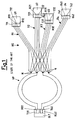
- Figure 1 shows a typical schematic configuration of an access network of the "PON" type, comprising a main terminal and four remote terminals, suitable to serve different users and to provide different types of traffic; said terminals are connected to each other through a two-way protection, both in the main network and in the secondary network.
- PON the "PON" type
- the data transmitted from the main terminal at the signal wavelength which can be equal, for instance, to 1.550 nm, are sent simultaneously, through branch elements, to all the user terminals, while the communication in the opposite direction is realised through a multiplexing system of the time division type.
- Said control techniques allow to detect with a high level of precision any deterioration and/or failures of the optical carrier, starting from the evaluation of the intensity of the radiation back-scattered by the carrier due to the Rayleigh effect, and are suitable to implement said working ways according to different approaches, as for instance the observation of reference reflections, the use of processing techniques of the back-scattering signal, the use of branch selectors or the use of multiplexing devices at the same wavelength of the branches.
- a purpose of the present invention is to solve the above mentioned disadvantage and in particular to show a control system, for optical network with a tree structure, which is fully passive (i.e. a system which does not use network electronics) and which is further suitable to control all the branches of a "PON" type network through the use of a traditional optical reflectometer with a single wavelength.
- a further purpose of the present invention is to disclose a control system, for optical networks with a tree structure, which is particularly simple and inexpensive and which can be realised by using traditional optical and electronic technologies and relatively inexpensive materials.
- control system for optical networks with a tree structure, according to claim 1, taken as a reference for brevity sake.
- the proposed solution allows to directly control all the branches of a "PON" type network and has the characteristic to use only passive components and an optical reflectometer with a single wavelength.
- the control system according to the invention is based on the use of optical reflectometers with a single wavelength emission, positioned in the spectrum window used for the control system, which, in an embodiment non limiting example, can be equal to 1.625 nm.
- the tree structure with point-to-multipoint type connections is transformed in a point-to-point structure at the wavelength of the control radiation, using a proper optical module, which allows to bypass the network at the branch points and a recycle module of the signal itself, installed at each user terminal.
- OLT indicates the main terminal of the "PON" optical network
- RP indicates a primary portion
- RS indicates a secondary portion
- N indicates the branch points of the network
- R1, R2, R3, R4 indicate four branches suitable to transmit the signal to a series of user terminals U, U1, U2, U3, U4
- TO1, TO2, T11, T12, T21, T22, T31, T32, T41, T42, T1, T2 indicate signal transmission devices
- RO1, RO2, R11, R12, R21, R22, R31, R32, R41, R42, R1, R2 indicate signal receiving devices
- OTDR indicates an Optical Time Domain Reflectometer
- SW indicates an optical selector element
- MD indicates a signal branch module
- ML indicates a module for recycling the control signal
- DM indicates wavelength multiplexing components
- TR indicates a termination component of the signal
- I indicates an input point of the branch module MD
- UD1, UD2, UD3, UD4 indicate a series of output units of
- the control system comprises a branch module MD, which is an integral part of the "PON" network and which allows the two-way connection of the main terminal OLT to each user terminal U, U1-U4, four wavelength multiplexing devices DM, which allow to separate and to gather the wavelengths of the signal SG and of the control SV radiation, according to need, and, in case, a terminal component TR to identify the end of the connection.
- a branch module MD which is an integral part of the "PON" network and which allows the two-way connection of the main terminal OLT to each user terminal U, U1-U4, four wavelength multiplexing devices DM, which allow to separate and to gather the wavelengths of the signal SG and of the control SV radiation, according to need, and, in case, a terminal component TR to identify the end of the connection.
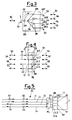
- the signal radiation SG and the control radiation SV are separated by a multiplexing device DM positioned at an inlet branch I of the branch module MD, so as that the signal radiation SG passes through the module MD, while the control radiation SV bypasses said module; said radiation are recombined at the output unit UD1 from the module MD, as shown in Figures 2 and 3.
- control radiation SV from the output unit UD3 is separated from the paying traffic and is recombined in the opposite direction by the multiplexing device DM positioned at the output unit UD4 of the branch R4 of the network; since all the components are of the two-way type, it could happen that the control radiation SV comes from the output unit UD4 and is directed to the output unit UD3.
- a termination component TR having the purpose to eliminate the residual control radiation SV and/or to detect the fiber end, as shown in Figure 3.
- each signal recycling module ML positioned at the various user terminals U1, U2, U3, U4, provides the use of four multiplexing devices DM, connected in such a way that the control radiation SV from the input unit I1 of the corresponding fiber is deviated and directed towards the multiplexing device DM of the input unit I3, in an opposite direction with respect to the direction of the control radiation SV at the input unit I1, while the control radiation SV from the input unit I2 is drawn out and injected on the fiber at the input unit I4. Since we are in the presence of two-way components, the control signal SV can pass through the component in the opposite direction.
- the transmission signal radiation SG continues, instead, without problems, its path from or towards the user terminals U, U1-U4.
- Figure 2 it is shown, in dotted line, the path of a control radiation SV in the case that the selection device SW connects the optical reflectometer OTDR to the fiber optics of the input unit I, in the primary network RP, connected to the transmission device TO1.
- control radiation SV bypasses the branch point N by means of the branch module MD, passes through the secondary network RS along the branch R1 and arrives at the user terminal U1. Said control radiation is then, through the recycling module ML, re-injected into another fiber of the branch R1 of the secondary network RS, in the opposite direction, until it reaches again the branch module MD, which allows the radiation SV to be directed again towards another fiber of the branch R4 of the secondary network RS towards the user terminal U4.
- the optical reflectometer as a measuring instrument, is placed close to the central side in order to share it with the highest number of users and in order to reach a low impact solution in terms of costs.
- the evaluation of the carrier deterioration can be performed in an automatic way by using and/or adjusting the algorithms realised in the reflectometer systems already commercially available.
- the implemented solution is flexible and potentially suitable to different network structures, also in function of specific requirements by the telecommunication operator with respect to the priority of some connections versus other ones.
- said automatic control technique obtained through the use of fully passive components and of single wavelength measuring instruments in the network, allows to monitor the branches of a "PON" type network, without trace overlapping, through the reduction of a network structure of the point-to-multipoint type to a network structure of the point-to-point type at the control wavelength.
Landscapes
- Physics & Mathematics (AREA)
- Electromagnetism (AREA)
- Engineering & Computer Science (AREA)
- Computer Networks & Wireless Communication (AREA)
- Signal Processing (AREA)
- Optical Communication System (AREA)
- Burglar Alarm Systems (AREA)
- Small-Scale Networks (AREA)
- Fluid-Pressure Circuits (AREA)
Applications Claiming Priority (2)
| Application Number | Priority Date | Filing Date | Title |
|---|---|---|---|
| ITMI981703 | 1998-07-23 | ||
| IT1998MI001703A IT1301848B1 (it) | 1998-07-23 | 1998-07-23 | Sistema passivo per la sorveglianza di reti ottiche di distibuzionecon struttura ad albero |
Publications (3)
| Publication Number | Publication Date |
|---|---|
| EP0975102A2 true EP0975102A2 (fr) | 2000-01-26 |
| EP0975102A3 EP0975102A3 (fr) | 2002-01-02 |
| EP0975102B1 EP0975102B1 (fr) | 2004-04-07 |
Family
ID=11380500
Family Applications (1)
| Application Number | Title | Priority Date | Filing Date |
|---|---|---|---|
| EP99202206A Expired - Lifetime EP0975102B1 (fr) | 1998-07-23 | 1999-07-06 | Un système passif de contrôle de réseaux optiques à structure en arbre |
Country Status (5)
| Country | Link |
|---|---|
| EP (1) | EP0975102B1 (fr) |
| AT (1) | ATE264029T1 (fr) |
| DE (1) | DE69916182D1 (fr) |
| ES (1) | ES2218945T3 (fr) |
| IT (1) | IT1301848B1 (fr) |
Cited By (5)
| Publication number | Priority date | Publication date | Assignee | Title |
|---|---|---|---|---|
| EP1315318A3 (fr) * | 2001-11-27 | 2004-05-12 | Multitel ASBL | Dispositif de contrôle d'un réseau de transmission de signaux optiques |
| FR2889741A1 (fr) * | 2005-08-09 | 2007-02-16 | Nexans Sa | Systeme de determination et de localisation de defauts par reflectometrie dans un reseau optique |
| WO2010107311A1 (fr) * | 2009-03-17 | 2010-09-23 | H.C. Van Dasselaar Holding B.V. | Procédé et système pour tester un faisceau de câbles comportant au moins deux fibres optiques |
| EP2383908A4 (fr) * | 2009-01-23 | 2012-06-06 | Huawei Tech Co Ltd | Procédé, appareil et système de détection dans un réseau de distribution optique |
| CN102893539A (zh) * | 2012-07-20 | 2013-01-23 | 华为技术有限公司 | 一种光网络监测模块、光通信系统及光网络监测方法 |
Family Cites Families (2)
| Publication number | Priority date | Publication date | Assignee | Title |
|---|---|---|---|---|
| US5680234A (en) * | 1994-10-20 | 1997-10-21 | Lucent Technologies Inc. | Passive optical network with bi-directional optical spectral slicing and loop-back |
| GB9506163D0 (en) * | 1995-03-27 | 1995-05-17 | Bicc Plc | Optical fibre and network |
-
1998
- 1998-07-23 IT IT1998MI001703A patent/IT1301848B1/it active IP Right Grant
-
1999
- 1999-07-06 DE DE69916182T patent/DE69916182D1/de not_active Expired - Lifetime
- 1999-07-06 AT AT99202206T patent/ATE264029T1/de not_active IP Right Cessation
- 1999-07-06 EP EP99202206A patent/EP0975102B1/fr not_active Expired - Lifetime
- 1999-07-06 ES ES99202206T patent/ES2218945T3/es not_active Expired - Lifetime
Cited By (8)
| Publication number | Priority date | Publication date | Assignee | Title |
|---|---|---|---|---|
| EP1315318A3 (fr) * | 2001-11-27 | 2004-05-12 | Multitel ASBL | Dispositif de contrôle d'un réseau de transmission de signaux optiques |
| BE1015198A4 (fr) * | 2001-11-27 | 2004-11-09 | Multitel Asbl | Dispositif optique commutable permettant la maintenance des reseaux optiques passifs arborescents par analyse reflectometrique dans le domaine temporel. |
| FR2889741A1 (fr) * | 2005-08-09 | 2007-02-16 | Nexans Sa | Systeme de determination et de localisation de defauts par reflectometrie dans un reseau optique |
| EP2383908A4 (fr) * | 2009-01-23 | 2012-06-06 | Huawei Tech Co Ltd | Procédé, appareil et système de détection dans un réseau de distribution optique |
| US8682163B2 (en) | 2009-01-23 | 2014-03-25 | Huawei Technologies Co., Ltd. | Detecting method, apparatus, and system in an optical distribution network |
| WO2010107311A1 (fr) * | 2009-03-17 | 2010-09-23 | H.C. Van Dasselaar Holding B.V. | Procédé et système pour tester un faisceau de câbles comportant au moins deux fibres optiques |
| CN102893539A (zh) * | 2012-07-20 | 2013-01-23 | 华为技术有限公司 | 一种光网络监测模块、光通信系统及光网络监测方法 |
| CN102893539B (zh) * | 2012-07-20 | 2015-08-26 | 华为技术有限公司 | 一种光网络监测模块、光通信系统及光网络监测方法 |
Also Published As
| Publication number | Publication date |
|---|---|
| EP0975102B1 (fr) | 2004-04-07 |
| ITMI981703A0 (it) | 1998-07-23 |
| ITMI981703A1 (it) | 2000-01-23 |
| EP0975102A3 (fr) | 2002-01-02 |
| DE69916182D1 (de) | 2004-05-13 |
| IT1301848B1 (it) | 2000-07-07 |
| ATE264029T1 (de) | 2004-04-15 |
| ES2218945T3 (es) | 2004-11-16 |
Similar Documents
| Publication | Publication Date | Title |
|---|---|---|
| US5491573A (en) | Optical signal transmission network | |
| US9281893B2 (en) | In-service monitoring of a fiberoptic network | |
| US9344189B2 (en) | System, a wavelength isolator and methods therein for supervision of a passive optical network | |
| US9673895B2 (en) | PON supervision using OTDR measurements | |
| EP1986350B1 (fr) | Unité de surveillance, réseau optique et procédé d'exploitation pour le réseau optique | |
| US7310134B2 (en) | Device and method of optical fiber condition monitoring in optical networks | |
| CN102104423A (zh) | 一种多分支无源光网络的故障检测方法和系统 | |
| ES2397024A2 (es) | Método y sistema para la monitorización de capa física en redes ópticas pasivas | |
| WO2008116309A1 (fr) | Procédé et système de détection dans de défauts dans un réseau optique à trajet multiple | |
| EP1650541A4 (fr) | Systeme permettant de controler une trajectoire optique a partir du cote terminal optique afin de detecter un probleme dans la trajectoire | |
| EP0975102B1 (fr) | Un système passif de contrôle de réseaux optiques à structure en arbre | |
| EP0622912B1 (fr) | Réseau de transmission de signaux optiques | |
| Montalvo et al. | WDM-PON preventive optical monitoring system with colourless reflectors | |
| WO1993016533A1 (fr) | Reseau de transmission de signaux optiques | |
| GB2413447A (en) | Short pulse loop back supervisory system | |
| EP1748580A1 (fr) | Procédé pour vérifier l'intégrité d'une ligne d'accès optique | |
| KR102106948B1 (ko) | 광학적 시간 영역 반사 측정기를 이용한 광선로 원거리 노드 식별 시스템 및 그 식별용 소자 | |
| CN118400028A (zh) | 光学时域反射仪系统 | |
| US12207031B2 (en) | Method and system to implement a demarcation point between a provider network and a customer network | |
| CN219514082U (zh) | 多波长可带光测试的光时域反射仪 | |
| JP2002022600A (ja) | 光線路試験装置および光線路試験方法 | |
| CN104737472B (zh) | 光网络监测装置、光通信系统及光网络监测方法 | |
| EP1713190A1 (fr) | Configuration de réseau pour transmission de signaux optiques | |
| Montalvo García et al. | WDM-PON Preventive Optical Monitoring System with Colourless Reflectors | |
| CN103095368B (zh) | 光测定装置 |
Legal Events
| Date | Code | Title | Description |
|---|---|---|---|
| PUAI | Public reference made under article 153(3) epc to a published international application that has entered the european phase |
Free format text: ORIGINAL CODE: 0009012 |
|
| AK | Designated contracting states |
Kind code of ref document: A2 Designated state(s): AT BE CH CY DE DK ES FI FR GB GR IE IT LI LU MC NL PT SE |
|
| AX | Request for extension of the european patent |
Free format text: AL;LT;LV;MK;RO;SI |
|
| PUAL | Search report despatched |
Free format text: ORIGINAL CODE: 0009013 |
|
| AK | Designated contracting states |
Kind code of ref document: A3 Designated state(s): AT BE CH CY DE DK ES FI FR GB GR IE IT LI LU MC NL PT SE |
|
| AX | Request for extension of the european patent |
Free format text: AL;LT;LV;MK;RO;SI |
|
| RIC1 | Information provided on ipc code assigned before grant |
Free format text: 7H 04B 10/08 A, 7H 04B 10/207 B |
|
| 17P | Request for examination filed |
Effective date: 20020517 |
|
| AKX | Designation fees paid |
Free format text: AT BE CH CY DE DK ES FI FR GB GR IE IT LI LU MC NL PT SE |
|
| 17Q | First examination report despatched |
Effective date: 20021003 |
|
| GRAP | Despatch of communication of intention to grant a patent |
Free format text: ORIGINAL CODE: EPIDOSNIGR1 |
|
| GRAS | Grant fee paid |
Free format text: ORIGINAL CODE: EPIDOSNIGR3 |
|
| GRAA | (expected) grant |
Free format text: ORIGINAL CODE: 0009210 |
|
| AK | Designated contracting states |
Kind code of ref document: B1 Designated state(s): AT BE CH CY DE DK ES FI FR GB GR IE IT LI LU MC NL PT SE |
|
| PG25 | Lapsed in a contracting state [announced via postgrant information from national office to epo] |
Ref country code: NL Free format text: LAPSE BECAUSE OF FAILURE TO SUBMIT A TRANSLATION OF THE DESCRIPTION OR TO PAY THE FEE WITHIN THE PRESCRIBED TIME-LIMIT Effective date: 20040407 Ref country code: LI Free format text: LAPSE BECAUSE OF FAILURE TO SUBMIT A TRANSLATION OF THE DESCRIPTION OR TO PAY THE FEE WITHIN THE PRESCRIBED TIME-LIMIT Effective date: 20040407 Ref country code: FR Free format text: LAPSE BECAUSE OF FAILURE TO SUBMIT A TRANSLATION OF THE DESCRIPTION OR TO PAY THE FEE WITHIN THE PRESCRIBED TIME-LIMIT Effective date: 20040407 Ref country code: FI Free format text: LAPSE BECAUSE OF FAILURE TO SUBMIT A TRANSLATION OF THE DESCRIPTION OR TO PAY THE FEE WITHIN THE PRESCRIBED TIME-LIMIT Effective date: 20040407 Ref country code: CY Free format text: LAPSE BECAUSE OF FAILURE TO SUBMIT A TRANSLATION OF THE DESCRIPTION OR TO PAY THE FEE WITHIN THE PRESCRIBED TIME-LIMIT Effective date: 20040407 Ref country code: CH Free format text: LAPSE BECAUSE OF FAILURE TO SUBMIT A TRANSLATION OF THE DESCRIPTION OR TO PAY THE FEE WITHIN THE PRESCRIBED TIME-LIMIT Effective date: 20040407 Ref country code: BE Free format text: LAPSE BECAUSE OF FAILURE TO SUBMIT A TRANSLATION OF THE DESCRIPTION OR TO PAY THE FEE WITHIN THE PRESCRIBED TIME-LIMIT Effective date: 20040407 Ref country code: AT Free format text: LAPSE BECAUSE OF FAILURE TO SUBMIT A TRANSLATION OF THE DESCRIPTION OR TO PAY THE FEE WITHIN THE PRESCRIBED TIME-LIMIT Effective date: 20040407 |
|
| REG | Reference to a national code |
Ref country code: GB Ref legal event code: FG4D |
|
| REG | Reference to a national code |
Ref country code: CH Ref legal event code: EP |
|
| REF | Corresponds to: |
Ref document number: 69916182 Country of ref document: DE Date of ref document: 20040513 Kind code of ref document: P |
|
| REG | Reference to a national code |
Ref country code: IE Ref legal event code: FG4D |
|
| PG25 | Lapsed in a contracting state [announced via postgrant information from national office to epo] |
Ref country code: LU Free format text: LAPSE BECAUSE OF NON-PAYMENT OF DUE FEES Effective date: 20040706 Ref country code: IE Free format text: LAPSE BECAUSE OF NON-PAYMENT OF DUE FEES Effective date: 20040706 |
|
| PG25 | Lapsed in a contracting state [announced via postgrant information from national office to epo] |
Ref country code: SE Free format text: LAPSE BECAUSE OF FAILURE TO SUBMIT A TRANSLATION OF THE DESCRIPTION OR TO PAY THE FEE WITHIN THE PRESCRIBED TIME-LIMIT Effective date: 20040707 Ref country code: GR Free format text: LAPSE BECAUSE OF FAILURE TO SUBMIT A TRANSLATION OF THE DESCRIPTION OR TO PAY THE FEE WITHIN THE PRESCRIBED TIME-LIMIT Effective date: 20040707 Ref country code: GB Free format text: LAPSE BECAUSE OF NON-PAYMENT OF DUE FEES Effective date: 20040707 Ref country code: DK Free format text: LAPSE BECAUSE OF FAILURE TO SUBMIT A TRANSLATION OF THE DESCRIPTION OR TO PAY THE FEE WITHIN THE PRESCRIBED TIME-LIMIT Effective date: 20040707 |
|
| PG25 | Lapsed in a contracting state [announced via postgrant information from national office to epo] |
Ref country code: DE Free format text: LAPSE BECAUSE OF FAILURE TO SUBMIT A TRANSLATION OF THE DESCRIPTION OR TO PAY THE FEE WITHIN THE PRESCRIBED TIME-LIMIT Effective date: 20040708 |
|
| PG25 | Lapsed in a contracting state [announced via postgrant information from national office to epo] |
Ref country code: MC Free format text: LAPSE BECAUSE OF NON-PAYMENT OF DUE FEES Effective date: 20040731 |
|
| NLV1 | Nl: lapsed or annulled due to failure to fulfill the requirements of art. 29p and 29m of the patents act | ||
| REG | Reference to a national code |
Ref country code: CH Ref legal event code: PL |
|
| REG | Reference to a national code |
Ref country code: ES Ref legal event code: FG2A Ref document number: 2218945 Country of ref document: ES Kind code of ref document: T3 |
|
| PLBE | No opposition filed within time limit |
Free format text: ORIGINAL CODE: 0009261 |
|
| STAA | Information on the status of an ep patent application or granted ep patent |
Free format text: STATUS: NO OPPOSITION FILED WITHIN TIME LIMIT |
|
| GBPC | Gb: european patent ceased through non-payment of renewal fee |
Effective date: 20040707 |
|
| EN | Fr: translation not filed | ||
| 26N | No opposition filed |
Effective date: 20050110 |
|
| REG | Reference to a national code |
Ref country code: IE Ref legal event code: MM4A |
|
| REG | Reference to a national code |
Ref country code: ES Ref legal event code: PC2A |
|
| PG25 | Lapsed in a contracting state [announced via postgrant information from national office to epo] |
Ref country code: PT Free format text: LAPSE BECAUSE OF NON-PAYMENT OF DUE FEES Effective date: 20040907 |
|
| PG25 | Lapsed in a contracting state [announced via postgrant information from national office to epo] |
Ref country code: IT Free format text: LAPSE BECAUSE OF NON-PAYMENT OF DUE FEES Effective date: 20100706 |
|
| PGRI | Patent reinstated in contracting state [announced from national office to epo] |
Ref country code: IT Effective date: 20110616 |
|
| PGFP | Annual fee paid to national office [announced via postgrant information from national office to epo] |
Ref country code: IT Payment date: 20180712 Year of fee payment: 20 Ref country code: ES Payment date: 20180801 Year of fee payment: 20 |
|
| REG | Reference to a national code |
Ref country code: ES Ref legal event code: FD2A Effective date: 20200721 |
|
| PG25 | Lapsed in a contracting state [announced via postgrant information from national office to epo] |
Ref country code: ES Free format text: LAPSE BECAUSE OF EXPIRATION OF PROTECTION Effective date: 20190707 |