EP0975112B1 - Method for synchronising external elements of a switching device using clock outputs - Google Patents
Method for synchronising external elements of a switching device using clock outputs Download PDFInfo
- Publication number
- EP0975112B1 EP0975112B1 EP99113313A EP99113313A EP0975112B1 EP 0975112 B1 EP0975112 B1 EP 0975112B1 EP 99113313 A EP99113313 A EP 99113313A EP 99113313 A EP99113313 A EP 99113313A EP 0975112 B1 EP0975112 B1 EP 0975112B1
- Authority
- EP
- European Patent Office
- Prior art keywords
- clock
- switching device
- clock outputs
- type
- outputs
- Prior art date
- Legal status (The legal status is an assumption and is not a legal conclusion. Google has not performed a legal analysis and makes no representation as to the accuracy of the status listed.)
- Expired - Lifetime
Links
- 230000001419 dependent effect Effects 0.000 description 3
- 230000000712 assembly Effects 0.000 description 2
- 238000000429 assembly Methods 0.000 description 2
- 230000005540 biological transmission Effects 0.000 description 2
- 210000000056 organ Anatomy 0.000 description 2
- 230000001360 synchronised effect Effects 0.000 description 2
- 150000001875 compounds Chemical class 0.000 description 1
- 230000008878 coupling Effects 0.000 description 1
- 238000010168 coupling process Methods 0.000 description 1
- 238000005859 coupling reaction Methods 0.000 description 1
- 230000009849 deactivation Effects 0.000 description 1
- 238000011156 evaluation Methods 0.000 description 1
- 230000011664 signaling Effects 0.000 description 1
Images
Classifications
-
- H—ELECTRICITY
- H04—ELECTRIC COMMUNICATION TECHNIQUE
- H04J—MULTIPLEX COMMUNICATION
- H04J3/00—Time-division multiplex systems
- H04J3/02—Details
- H04J3/06—Synchronising arrangements
- H04J3/0635—Clock or time synchronisation in a network
- H04J3/0685—Clock or time synchronisation in a node; Intranode synchronisation
Definitions
- the invention relates to an arrangement for the synchronization of external components of a switching device.
- Existing switching devices in particular private branch exchanges, have clock outputs which are always permanently switched.
- the supply cable or the corresponding connector assembly must be pulled.
- each switch may act as a master or slave clock.
- Each switch has a mechanism for selecting the clock with the highest quality or quality.
- clock outputs thereafter, which type of external components can be connected.
- the control of the clock outputs is dependent on their function, in particular by the central control of the switching device. All types of clock outputs can be manually switched, for example via a service program.
- For some kind of clock outputs is an automatic on or off possible, so that no removal of cables or connection assemblies is necessary for deactivation.
- an automatic control switching on or off means a more accurate and reliable operation.
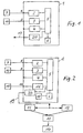
- FIG. 1 shows the connection of external components to a switching device via clock outputs
- Figure 2 shows a system network of switching equipment with external components connected.
- Figure 1 shows schematically a switching device 1, e.g. a private branch exchange, with a plurality of external component connections 7, 10, for example external multiplexers, antennas, with a plurality of external component connections 4, 20, for example subscriber terminals or trunk lines, e.g. 19, a coupling network 5 and a central controller 6.
- External components 7, 10 are connected via clock outputs 8, 9 to terminal assemblies - here connection modules 2 and 3 - connected. For the connection of external components several connections per switching device or connection module are possible.
- a connection module tells the central controller 6 that there are clock outputs on it as well as which type of Clock outputs.
- the clock outputs are to be distinguished according to which type of external components 7, 10 are connected. At least two types of external components and thus also two types of clock outputs are distinguished here. All types of clock outputs are manually z. B. be switchable via a service program. Furthermore, for a certain type of clock outputs, which depends on their function, an automatic control, that is, in particular a connection or disconnection from the central controller 6 of the switching device 1, for example, by a corresponding system software.
- the type of clock output is defined in each case by a specific connection element type of connectable external components. Because of this type of terminal organ of the clock output, the central controller 6 determines whether automatic control (on or off) is required for this clock output or not. The automatic switching on and off of the clock outputs is initiated by the central controller 6. This controller determines when to enable or disable the clock outputs.
- the external clock generator 15 connected to the switching device 1 is given precedence as the clock standard for the system network, irrespective of whether the switching devices 11, 12, 13 or 14 have other clock sources for synchronization, such as the office clock DIVO (digital mediation, location) - management.
- DIVO digital mediation, location
- connection module In order for an external clock generator 15 connected to a connection module - here 16 - to be able to be recognized by the central controller 6, the connection module must be designed to be correspondingly configurable, eg by a service program. It is determined that it is an external clock generator due to the terminal organ type of the clock input 18. Once the connector assembly 16 determines that the external clock generator 15 is providing a clock, it reports this to the central controller. The controller 6 is an evaluation logic 17 associated with the selection of the synchronization clock. If the external clock generator 15 supplies a clock, it is given priority as a clock standard before, for example, a DIVO connection.
- the further switching devices 11, 12, 13, 14 is in particular via a signaling channel in the compound line at the output 19, for example, the D channel in ISDN, communicated that the external clock generator 15 is available as a clock standard for synchronization purposes.
- the external clock generator 15 is now irrespective of which of the switching devices it is connected, the priority as clock normal for synchronization for the other switching equipment of the network granted so that all switching devices synchronize to the switching device with external clock connected, even if they have their own Have DIVO connection.
- External components can thus be easily synchronized to a very accurate clock standard of the system network.
Landscapes
- Engineering & Computer Science (AREA)
- Computer Networks & Wireless Communication (AREA)
- Signal Processing (AREA)
- Synchronisation In Digital Transmission Systems (AREA)
- Use Of Switch Circuits For Exchanges And Methods Of Control Of Multiplex Exchanges (AREA)
- Electric Clocks (AREA)
Abstract
Description
Die Erfindung geht aus von einer Anordnung zur Synchronisation von externen Komponenten einer Vermittlungseinrichtung. Bestehende Vermittlungseinrichtungen, insbesondere Nebenstellenanlagen, weisen Taktausgänge auf, die immer daueraktiv geschaltet sind. Um eine Verbindung zu einer angeschlossenen externen Komponente zu unterbrechen, muß das Zuleitungskabel oder die entsprechende Anschlußbaugruppe gezogen werden.The invention relates to an arrangement for the synchronization of external components of a switching device. Existing switching devices, in particular private branch exchanges, have clock outputs which are always permanently switched. To break a connection to a connected external component, the supply cable or the corresponding connector assembly must be pulled.
Das Dokument
Mit den Maßnahmen gemäß den Merkmalen des Anspruchs 1 beziehungsweise den Ausgestaltungen aufzeigenden Unteransprüchen ist es möglich, Taktausgänge danach zu unterscheiden, welche Art von externen Komponenten anschließbar sind. Die Steuerung der Taktausgänge erfolgt abhängig von ihrer Funktion, insbesondere durch die zentrale Steuerung der Vermittlungseinrichtung. Alle Arten von Taktausgängen können manuell, beispielsweise über ein Serviceprogramm schaltbar sein. Für eine Art von Taktausgängen ist eine automatische An- bzw. Abschaltung möglich, so daß zur Deaktivierung kein Ziehen von Kabeln oder Anschlußbaugruppen notwendig ist. Für externe Komponenten, die von der Synchronisation in einem Anlagenverbund abhängig sind, wie zum Beispiel Multiplexer für die Datenübertragung, bedeutet eine automatische Steuerung (An- bzw. Abschalten) eine genauere und zuverlässigere Funktionsweise.With the measures according to the features of
Anhand der Zeichnungen werden Ausführungsbeispiele der Erfindung näher erläutert. Es zeigen
Figur 1 den Anschluß von externen Komponenten an eine Vermittlungseinrichtung über Taktausgänge,
Figur 2 ein Anlagenverbund von Vermittlungseinrichtungen mit angeschlossenen externen Komponenten.Reference to the drawings embodiments of the invention will be explained in more detail. Show it
FIG. 1 shows the connection of external components to a switching device via clock outputs,
Figure 2 shows a system network of switching equipment with external components connected.
Figur 1 zeigt schematisch eine Vermittlungseinrichtung 1, z.B. eine Nebenstellenanlage, mit mehreren Anschlußbaugruppen 2, 3 für externe Komponenten 7, 10, beispielsweise externe Multiplexer, Antennen, mit mehreren Anschlußbaugruppen 4, 20 für externe Komponenten, beispielsweise Teilnehmerendeinrichtungen oder Amts- bzw. Verbundleitungen z.B. 19, einem Koppelnetzwerk 5 sowie einer zentralen Steuerung 6. Externe Komponenten 7, 10 sind über Taktausgänge 8, 9 an Anschlußbaugruppen - hier Anschlußbaugruppen 2 und 3 - angeschlossen. Für den Anschluß externer Komponenten sind mehrere Anschlüsse pro Vermittlungseinrichtung oder Anschlußbaugruppe möglich.Figure 1 shows schematically a
Eine Anschlußbaugruppe teilt bei Ihrer Inbetriebnahme (Anmeldung) der zentralen Steuerung 6 mit, daß auf ihr Taktausgänge vorhanden sind und auch welche Art von Taktausgängen. Die Taktausgänge sollen danach unterschieden werden, welche Art von externen Komponenten 7, 10 angeschlossen sind. Es werden hier zumindest zwei Arten von externen Komponenten und damit auch zwei Arten von Taktausgängen unterschieden. Alle Arten von Taktausgängen sollen manuell z. B. über ein Serviceprogramm schaltbar sein. Weiterhin erfolgt für eine bestimmte Art von Taktausgängen, die von ihrer Funktion abhängt, eine automatische Steuerung, das heißt insbesondere ein An- bzw. Abschalten von der zentralen Steuerung 6 der Vermittlungseinrichtung 1 aus, beispielsweise durch eine entsprechende Anlagensoftware.When you commission (login), a connection module tells the
Die Art des Taktausganges wird jeweils durch einen bestimmten Anschlußorgan-Typ der anschließbaren externen Komponenten definiert. Aufgrund dieses Anschlußorgan-Typs des Taktausganges stellt die zentrale Steuerung 6 fest, ob für diesen Taktausgang eine automatische Steuerung (An- bzw. Abschaltung) erforderlich ist oder nicht. Die automatische An- und Abschaltung der Taktausgänge wird von der zentralen Steuerung 6 eingeleitet. Diese Steuerung stellt fest, wann die Taktausgänge aktiviert bzw. deaktiviert werden sollen.The type of clock output is defined in each case by a specific connection element type of connectable external components. Because of this type of terminal organ of the clock output, the
Für die Steuerung der Taktausgänge in Abhängigkeit ihrer Funktion ist eine automatische und/oder manuelle Schaltung möglich. Für externe Komponenten 7, die von der Synchronistation der Vermittlungsanlagen im Anlagenverbund (Figur 2) abhängig sind, wie z. B. Multiplexer für die Datenübertragung, bedeutet die automatische Steuerung (An- bzw. Abschaltung)eine genauere Funktionsweise. Aber auch für externe Komponenten 10, die davon unabhängig sind, z.B. Antennen, werden mit dem Anlagentakt synchronisiert.For the control of the clock outputs depending on their function, an automatic and / or manual switching is possible. For
Ist eine Vermittlungseinrichtung 1 gemäß Figur 2 für weitere Vermittlungseinrichtungen 11, 12, 13, 14 in einem Anlagenverbund Taktmaster, das heißt die anderen Vermittlungseinrichtungen 11, 12, 13, 14 leiten von ihr den Takt ab, werden die Taktausgänge, die von der Synchronisation im Anlagenverbund abhängen, aktiviert. Ist die Vermittlungseinrichtung 1 Stand-alone, das heißt es sind keine Nachbar-Vermittlungseinrichtungen angeschlossen, oder sie ist Taktslave, das heißt sie leitet von einer anderen Vermittlungseinrichtung den Takt ab, dann müssen diese Taktausgänge deaktiviert werden.Is a
Bei der Ausgestaltung nach Figur 2 wird dem an die Vermittlungseinrichtung 1 angeschlossenen externen Taktgenerator 15 der Vorrang als Taktnormal für den Anlagenverbund gegeben unabhängig davon, ob die Vermittlungseinrichtungen 11, 12, 13 oder 14 über andere Taktquellen zur Synchronisation verfügen, wie beispielsweise den Amtstakt über eine DIVO (digitale Vermittlung, Ort) - Leitung.In the embodiment according to FIG. 2, the
Damit ein an eine Anschlußbaugruppe - hier 16 - angeschlossener externer Taktgenerator 15 von der zentralen Steuerung 6 erkannt werden kann, muß die Anschlußbaugruppe, z.B. durch ein Serviceprogramm, entsprechend konfigurierbar ausgebildet sein. Dabei wird aufgrund des Anschlußorgan-Typs des Takteingangs 18 festgelegt, daß es sich um einen externen Taktgenerator handelt. Sobald die Anschlußbaugruppe 16 feststellt, daß der externe Taktgenerator 15 einen Takt liefert, meldet sie dies der zentralen Steuerung. Der Steuerung 6 ist eine Auswertelogik 17 zugeordnet für die Auswahl des Synchronisationstaktes. Liefert der externe Taktgenerator 15 einen Takt, wird diesem der Vorrang als Taktnormal vor beispielsweise einem DIVO-Anschluß gegeben. Den weiteren Vermittlungseinrichtungen 11, 12, 13, 14 wird insbesondere über einen Signalisierungskanal in der Verbundleitung am Ausgang 19, z.B. den D-Kanal im ISDN, mitgeteilt, daß der externe Taktgenerator 15 als Taktnormal für Synchronisationszwecke zur Verfügung steht. Dem externen Taktgenerator 15 wird nun unabhängig davon, an welcher der Vermittlungseinrichtungen er angeschlossen ist, der Vorrang als Taktnormal zur Synchronisation für die übrigen Vermittlungseinrichtungen des Verbundes eingeräumt, so daß sich alle Vermittlungseinrichtungen auf die Vermittlungseinrichtung mit angeschlossenem externen Taktgenerator synchronisieren, auch wenn sie einen eigenen DIVO-Anschluß aufweisen.In order for an
Externe Komponenten können so auf einfache Weise auf ein sehr genaues Taktnormal des Anlagenverbundes synchronisiert werden.External components can thus be easily synchronized to a very accurate clock standard of the system network.
Claims (7)
- Arrangement for synchronizing external components (7, 10) of a switching device (1) using the clock outputs (8, 9) thereof, characterized by clock outputs (8) of at least one type which can be connected or disconnected from the switching device (1) depending on their function.
- Arrangement according to Claim 1, having clock outputs (8, 9) of two types, in which case both types can be manually switched and one type of clock outputs (8) can be automatically connected and disconnected from a central controller (6) of the switching device (1).
- Arrangement according to Claim 1 or 2, characterized in that the clock outputs (8) of one type can be activated when the switching device (1) operates as a clock master in a system group.
- Arrangement according to Claim 1 or 2, characterized in that the clock outputs (8) of one type can be deactivated when they operate in the stand-alone mode or as a clock slave in a system group.
- Arrangement according to one of Claims 1 to 4, characterized in that the clock outputs (8, 9) are provided on a subscriber line module (2, 3) of the switching device, in which case, when a subscriber line module (3) is started, a central controller (6) of the switching device (1) is informed that clock outputs have been provided on it and is also informed of the type of clock outputs.
- Arrangement according to one of Claims 1 to 5, characterized in that the type of a clock output depends on its connecting element which in turn depends on the type of external component (7, 10) connected.
- Arrangement according to one of Claims 1 to 6, characterized in that, for external components (7) which depend on the synchronization of the switching device (1) in a system group, the respective clock output (8) which can be connected to said components is controlled automatically.
Applications Claiming Priority (2)
| Application Number | Priority Date | Filing Date | Title |
|---|---|---|---|
| DE19833282 | 1998-07-24 | ||
| DE19833282A DE19833282A1 (en) | 1998-07-24 | 1998-07-24 | Method for synchronizing external components of a switching device via clock outputs |
Publications (3)
| Publication Number | Publication Date |
|---|---|
| EP0975112A2 EP0975112A2 (en) | 2000-01-26 |
| EP0975112A3 EP0975112A3 (en) | 2004-05-12 |
| EP0975112B1 true EP0975112B1 (en) | 2007-09-12 |
Family
ID=7875129
Family Applications (1)
| Application Number | Title | Priority Date | Filing Date |
|---|---|---|---|
| EP99113313A Expired - Lifetime EP0975112B1 (en) | 1998-07-24 | 1999-07-09 | Method for synchronising external elements of a switching device using clock outputs |
Country Status (3)
| Country | Link |
|---|---|
| EP (1) | EP0975112B1 (en) |
| AT (1) | ATE373261T1 (en) |
| DE (2) | DE19833282A1 (en) |
Family Cites Families (4)
| Publication number | Priority date | Publication date | Assignee | Title |
|---|---|---|---|---|
| DE59103822D1 (en) * | 1991-09-02 | 1995-01-19 | Siemens Ag | Method and device for synchronizing a clock device of a telecommunications switching system. |
| DE4131061C1 (en) * | 1991-09-18 | 1992-09-10 | Siemens Ag, 8000 Muenchen, De | Switching procedure for external reference pulse signal in telephone exchange - conducting external reference signals to module delivering reference pulse series for synchronising central pulse generator or clock |
| US5577075A (en) * | 1991-09-26 | 1996-11-19 | Ipc Information Systems, Inc. | Distributed clocking system |
| DE4227283C1 (en) * | 1992-08-18 | 1993-12-16 | Siemens Ag | Method for automatically coupling a communication system to an external reference clock |
-
1998
- 1998-07-24 DE DE19833282A patent/DE19833282A1/en not_active Withdrawn
-
1999
- 1999-07-09 DE DE59914495T patent/DE59914495D1/en not_active Expired - Lifetime
- 1999-07-09 AT AT99113313T patent/ATE373261T1/en not_active IP Right Cessation
- 1999-07-09 EP EP99113313A patent/EP0975112B1/en not_active Expired - Lifetime
Non-Patent Citations (1)
| Title |
|---|
| None * |
Also Published As
| Publication number | Publication date |
|---|---|
| DE59914495D1 (en) | 2007-10-25 |
| DE19833282A1 (en) | 2000-01-27 |
| EP0975112A3 (en) | 2004-05-12 |
| ATE373261T1 (en) | 2007-09-15 |
| EP0975112A2 (en) | 2000-01-26 |
Similar Documents
| Publication | Publication Date | Title |
|---|---|---|
| DE69129258T2 (en) | Switching system of optical transmission lines for interference protection | |
| EP3955529B1 (en) | Unit for a bus system, master / slave bus system with a plurality of units and method for addressing units of a bus system | |
| EP1757112B1 (en) | Data transmission device and method for transmitting data at reduced failure risk | |
| EP1356619B1 (en) | Method and electro-optical circuit arrangement for line protection in a wdm data transmission link | |
| DE19615174B4 (en) | Device for signal transmission in a synchronous digital hierarchical network | |
| EP0975112B1 (en) | Method for synchronising external elements of a switching device using clock outputs | |
| EP1695158B1 (en) | Intrinsically safe data transmission device | |
| EP1151569B1 (en) | Add-drop-multiplexer and optical wavelength division multiplex transmission system | |
| DE60034412T2 (en) | communication system | |
| DE102008037610A1 (en) | Device and method for the selective switching of two masters for assigned slaves | |
| DE4038749C1 (en) | Subscriber peripheral circuit for ISDN - has coupling device to connect one of subscriber peripherals to digital network line | |
| DE4306032A1 (en) | Circuit arrangement for electro-optical changeover to standby during operation in communications systems | |
| EP0975113B1 (en) | Method for synchronising interconnected switching devices | |
| DE4139265C2 (en) | Telecommunications data access device | |
| EP1252791B1 (en) | Optical cross-connect | |
| EP0549862B1 (en) | Optical communication network | |
| DE4122276A1 (en) | Digital communication system allowing time division multiplexing - sends fault alarm via all other exchange-interconnecting cables if cable fails from first exchange drawing clock signal from this cable | |
| DE102010005989B4 (en) | Method for data transmission in time-controlled communication systems and time-controlled communication system | |
| DE69832080T2 (en) | MODULAR DIGITAL TELEPHONE SYSTEM AND METHOD WITH A UNIVERSAL TELEPHONE SYSTEM | |
| DE69430737T2 (en) | SWITCHING DEVICE | |
| DE19623480C1 (en) | Method for generating an output clock signal that can be used to control a data output as a function of one of a plurality of input clock signals | |
| DE3121774C2 (en) | ||
| EP4300898A2 (en) | Vacuum machine | |
| DE3307347C2 (en) | ||
| DE4315022C1 (en) | Digital TDM communications system - with spaced coupling fields coupled via intermediate adaptors within central module |
Legal Events
| Date | Code | Title | Description |
|---|---|---|---|
| PUAI | Public reference made under article 153(3) epc to a published international application that has entered the european phase |
Free format text: ORIGINAL CODE: 0009012 |
|
| AK | Designated contracting states |
Kind code of ref document: A2 Designated state(s): AT BE CH CY DE DK ES FI FR GB GR IE IT LI LU MC NL PT SE |
|
| AX | Request for extension of the european patent |
Free format text: AL;LT;LV;MK;RO;SI |
|
| RAP1 | Party data changed (applicant data changed or rights of an application transferred) |
Owner name: TENOVIS GMBH & CO. KG |
|
| PUAL | Search report despatched |
Free format text: ORIGINAL CODE: 0009013 |
|
| AK | Designated contracting states |
Kind code of ref document: A3 Designated state(s): AT BE CH CY DE DK ES FI FR GB GR IE IT LI LU MC NL PT SE |
|
| AX | Request for extension of the european patent |
Extension state: AL LT LV MK RO SI |
|
| RIC1 | Information provided on ipc code assigned before grant |
Ipc: 7H 04Q 11/04 B Ipc: 7H 04J 3/06 B Ipc: 7G 06F 1/10 A |
|
| AKX | Designation fees paid | ||
| 17P | Request for examination filed |
Effective date: 20041210 |
|
| RBV | Designated contracting states (corrected) |
Designated state(s): AT BE CH CY DE DK ES FI FR GB GR IE IT LI LU MC NL PT SE |
|
| REG | Reference to a national code |
Ref country code: DE Ref legal event code: 8566 |
|
| 17Q | First examination report despatched |
Effective date: 20050329 |
|
| GRAP | Despatch of communication of intention to grant a patent |
Free format text: ORIGINAL CODE: EPIDOSNIGR1 |
|
| GRAS | Grant fee paid |
Free format text: ORIGINAL CODE: EPIDOSNIGR3 |
|
| GRAA | (expected) grant |
Free format text: ORIGINAL CODE: 0009210 |
|
| AK | Designated contracting states |
Kind code of ref document: B1 Designated state(s): AT BE CH CY DE DK ES FI FR GB GR IE IT LI LU MC NL PT SE |
|
| REG | Reference to a national code |
Ref country code: GB Ref legal event code: FG4D Free format text: NOT ENGLISH |
|
| REG | Reference to a national code |
Ref country code: CH Ref legal event code: EP |
|
| REF | Corresponds to: |
Ref document number: 59914495 Country of ref document: DE Date of ref document: 20071025 Kind code of ref document: P |
|
| REG | Reference to a national code |
Ref country code: IE Ref legal event code: FG4D Free format text: LANGUAGE OF EP DOCUMENT: GERMAN |
|
| GBT | Gb: translation of ep patent filed (gb section 77(6)(a)/1977) |
Effective date: 20071121 |
|
| PG25 | Lapsed in a contracting state [announced via postgrant information from national office to epo] |
Ref country code: FI Free format text: LAPSE BECAUSE OF FAILURE TO SUBMIT A TRANSLATION OF THE DESCRIPTION OR TO PAY THE FEE WITHIN THE PRESCRIBED TIME-LIMIT Effective date: 20070912 |
|
| NLV1 | Nl: lapsed or annulled due to failure to fulfill the requirements of art. 29p and 29m of the patents act | ||
| ET | Fr: translation filed | ||
| PG25 | Lapsed in a contracting state [announced via postgrant information from national office to epo] |
Ref country code: NL Free format text: LAPSE BECAUSE OF FAILURE TO SUBMIT A TRANSLATION OF THE DESCRIPTION OR TO PAY THE FEE WITHIN THE PRESCRIBED TIME-LIMIT Effective date: 20070912 Ref country code: GR Free format text: LAPSE BECAUSE OF FAILURE TO SUBMIT A TRANSLATION OF THE DESCRIPTION OR TO PAY THE FEE WITHIN THE PRESCRIBED TIME-LIMIT Effective date: 20071213 Ref country code: ES Free format text: LAPSE BECAUSE OF FAILURE TO SUBMIT A TRANSLATION OF THE DESCRIPTION OR TO PAY THE FEE WITHIN THE PRESCRIBED TIME-LIMIT Effective date: 20071223 |
|
| REG | Reference to a national code |
Ref country code: IE Ref legal event code: FD4D |
|
| PG25 | Lapsed in a contracting state [announced via postgrant information from national office to epo] |
Ref country code: PT Free format text: LAPSE BECAUSE OF FAILURE TO SUBMIT A TRANSLATION OF THE DESCRIPTION OR TO PAY THE FEE WITHIN THE PRESCRIBED TIME-LIMIT Effective date: 20080212 |
|
| PG25 | Lapsed in a contracting state [announced via postgrant information from national office to epo] |
Ref country code: SE Free format text: LAPSE BECAUSE OF FAILURE TO SUBMIT A TRANSLATION OF THE DESCRIPTION OR TO PAY THE FEE WITHIN THE PRESCRIBED TIME-LIMIT Effective date: 20071212 |
|
| PLBE | No opposition filed within time limit |
Free format text: ORIGINAL CODE: 0009261 |
|
| STAA | Information on the status of an ep patent application or granted ep patent |
Free format text: STATUS: NO OPPOSITION FILED WITHIN TIME LIMIT |
|
| 26N | No opposition filed |
Effective date: 20080613 |
|
| PG25 | Lapsed in a contracting state [announced via postgrant information from national office to epo] |
Ref country code: IE Free format text: LAPSE BECAUSE OF FAILURE TO SUBMIT A TRANSLATION OF THE DESCRIPTION OR TO PAY THE FEE WITHIN THE PRESCRIBED TIME-LIMIT Effective date: 20070912 |
|
| REG | Reference to a national code |
Ref country code: CH Ref legal event code: PL |
|
| PG25 | Lapsed in a contracting state [announced via postgrant information from national office to epo] |
Ref country code: MC Free format text: LAPSE BECAUSE OF NON-PAYMENT OF DUE FEES Effective date: 20080731 |
|
| PG25 | Lapsed in a contracting state [announced via postgrant information from national office to epo] |
Ref country code: LI Free format text: LAPSE BECAUSE OF NON-PAYMENT OF DUE FEES Effective date: 20080731 Ref country code: CH Free format text: LAPSE BECAUSE OF NON-PAYMENT OF DUE FEES Effective date: 20080731 |
|
| PG25 | Lapsed in a contracting state [announced via postgrant information from national office to epo] |
Ref country code: CY Free format text: LAPSE BECAUSE OF FAILURE TO SUBMIT A TRANSLATION OF THE DESCRIPTION OR TO PAY THE FEE WITHIN THE PRESCRIBED TIME-LIMIT Effective date: 20070912 |
|
| PG25 | Lapsed in a contracting state [announced via postgrant information from national office to epo] |
Ref country code: AT Free format text: LAPSE BECAUSE OF NON-PAYMENT OF DUE FEES Effective date: 20080709 |
|
| PG25 | Lapsed in a contracting state [announced via postgrant information from national office to epo] |
Ref country code: DK Free format text: LAPSE BECAUSE OF FAILURE TO SUBMIT A TRANSLATION OF THE DESCRIPTION OR TO PAY THE FEE WITHIN THE PRESCRIBED TIME-LIMIT Effective date: 20070912 |
|
| PG25 | Lapsed in a contracting state [announced via postgrant information from national office to epo] |
Ref country code: LU Free format text: LAPSE BECAUSE OF NON-PAYMENT OF DUE FEES Effective date: 20080709 |
|
| PG25 | Lapsed in a contracting state [announced via postgrant information from national office to epo] |
Ref country code: BE Free format text: LAPSE BECAUSE OF NON-PAYMENT OF DUE FEES Effective date: 20080731 |
|
| PGFP | Annual fee paid to national office [announced via postgrant information from national office to epo] |
Ref country code: FR Payment date: 20100802 Year of fee payment: 12 Ref country code: DE Payment date: 20100726 Year of fee payment: 12 |
|
| PGFP | Annual fee paid to national office [announced via postgrant information from national office to epo] |
Ref country code: GB Payment date: 20100726 Year of fee payment: 12 |
|
| PG25 | Lapsed in a contracting state [announced via postgrant information from national office to epo] |
Ref country code: IT Free format text: LAPSE BECAUSE OF NON-PAYMENT OF DUE FEES Effective date: 20080731 |
|
| GBPC | Gb: european patent ceased through non-payment of renewal fee |
Effective date: 20110709 |
|
| REG | Reference to a national code |
Ref country code: FR Ref legal event code: ST Effective date: 20120330 |
|
| PG25 | Lapsed in a contracting state [announced via postgrant information from national office to epo] |
Ref country code: DE Free format text: LAPSE BECAUSE OF NON-PAYMENT OF DUE FEES Effective date: 20120201 Ref country code: FR Free format text: LAPSE BECAUSE OF NON-PAYMENT OF DUE FEES Effective date: 20110801 |
|
| REG | Reference to a national code |
Ref country code: DE Ref legal event code: R119 Ref document number: 59914495 Country of ref document: DE Effective date: 20120201 |
|
| PG25 | Lapsed in a contracting state [announced via postgrant information from national office to epo] |
Ref country code: GB Free format text: LAPSE BECAUSE OF NON-PAYMENT OF DUE FEES Effective date: 20110709 |