EP0975129A2 - Dispositif et méthode pour adapter des appareils accessoires à un terminal analogique de télécommunication - Google Patents
Dispositif et méthode pour adapter des appareils accessoires à un terminal analogique de télécommunication Download PDFInfo
- Publication number
- EP0975129A2 EP0975129A2 EP99110117A EP99110117A EP0975129A2 EP 0975129 A2 EP0975129 A2 EP 0975129A2 EP 99110117 A EP99110117 A EP 99110117A EP 99110117 A EP99110117 A EP 99110117A EP 0975129 A2 EP0975129 A2 EP 0975129A2
- Authority
- EP
- European Patent Office
- Prior art keywords
- output unit
- network access
- voice input
- access line
- additional
- Prior art date
- Legal status (The legal status is an assumption and is not a legal conclusion. Google has not performed a legal analysis and makes no representation as to the accuracy of the status listed.)
- Granted
Links
Images


Classifications
-
- H—ELECTRICITY
- H04—ELECTRIC COMMUNICATION TECHNIQUE
- H04M—TELEPHONIC COMMUNICATION
- H04M1/00—Substation equipment, e.g. for use by subscribers
- H04M1/60—Substation equipment, e.g. for use by subscribers including speech amplifiers
- H04M1/6033—Substation equipment, e.g. for use by subscribers including speech amplifiers for providing handsfree use or a loudspeaker mode in telephone sets
-
- H—ELECTRICITY
- H04—ELECTRIC COMMUNICATION TECHNIQUE
- H04M—TELEPHONIC COMMUNICATION
- H04M1/00—Substation equipment, e.g. for use by subscribers
- H04M1/02—Constructional features of telephone sets
- H04M1/21—Combinations with auxiliary equipment, e.g. with clocks or memoranda pads
- H04M1/215—Combinations with auxiliary equipment, e.g. with clocks or memoranda pads by non-intrusive coupling means, e.g. acoustic couplers
Definitions
- the invention relates to a method for adapting additional devices, such as answering machines, hands-free systems, dialing aids and the like, to an analog terminal for telecommunications, especially on a phone.
- the invention relates furthermore an apparatus for performing the method.
- Telecommunications terminal equipment in particular simple telephones, are often to be replaced by additional devices, e.g. Answering machine, speakerphone, Election aids, be upgraded.
- additional devices e.g. Answering machine, speakerphone, Election aids
- the terminal device to be expanded directly take by either existing modification additions of the terminals used or, if these are not available, the internal Wiring of the terminal is modified accordingly.
- the first Approach requires that the end device to be expanded for Modifications for an additional device is prepared. This is often not the case, especially with simple analog telephones.
- the second approach assumes that the user of the terminal either has sufficient technical knowledge to handle the internal Interconnection of the terminal in a suitable manner, or ready to change is to hire an appropriate specialist.
- the invention is therefore based on the object of a method for Adaptation of additional devices to analog terminal devices for the Telecommunications, especially in the speech path of the to be expanded Additional equipment interfering with terminal equipment, to be specified at which interferes with the analog terminal to be expanded become.
- the invention is also based on the object Specify device which for upgrading terminal equipment with Additional devices can be used universally.
- the task is solved by a method for the adaptation of Additional devices to an analog terminal for telecommunications according to claim 1.
- the task is still solved by a device for performing the method according to Claim 6.
- Advantageous further developments of the method and Devices are described in subclaims 2 to 5 and 7 to 9, respectively.
- the solution according to the invention is based on the fact that the insertion of a Additional device in the speech path of an analog terminal is done in such a way that the actuation functions for a connection setup or clearing are required, can be carried out in the usual way and the electrical conditions in view of the telephone network remain unchanged.
- the mechanical functions e.g. Entering dialing commands on a keyboard
- the speech functions the terminal separated by a parallel network connection of the to be expanded analog terminal and the additional device under Avoid influencing the standardized line termination resistance is made.
- the original speech path is decoupled from the Terminal device with high impedance on its network access line accessed, receiving the standardized line termination resistance remains.
- the tapped signal is preferably proportional to Speech signal coming from the telephone network to the terminal is transmitted. This via the network access line directly to the end device transmitted voice signal is in contrast to normal functioning of the terminal in the present invention no further Realization of the speech function exploited.
- the original speech path and voice input and output device the terminal device, in particular the telephone handset, rather remains unused.
- the telephone handset can be removed.
- the additional device To implement a new speech path in which the additional device is located can be inserted without any problems, this is now from the network access line high-impedance tapped speech signal or one proportional signal to the additional device and to one of the Terminal device electrically separated voice input and output unit guided.
- the tapped speech signal is preferably used before coupling in the additional device or the voice input and output unit amplified to bring it up to about the signal level that the above the network access line has transmitted signal.
- "coming" speech signals that is, those that are transmitted via the Telephone network to be transmitted to the terminal, to the additional device as well as to a speech output unit, such as a loudspeaker, headed.
- the user can do this in a known manner in an acoustic Hear the converted voice signal.
- the additional device record the voice signals or otherwise influence them take them e.g. Play loudly as a speakerphone.
- the "outgoing" signals that is to say those which are generally entered acoustically by the user and for transmission over the telephone network into an electronic one Signal-converted speech signals are in the invention on a Voice input unit entered, which is also from the upgraded Terminal is electrically isolated.
- the original speech path of the end device remains unused according to the invention also for the input of voice signals.
- the device to be upgraded can also be used at any time Additional devices work, i.e. the original speech path becomes not completely disabled or interrupted.
- an output signal which is usually also spoken language corresponds, e.g. an announcement.
- the output signal of the voice input unit and / or the additional device then becomes high-resistance while maintaining the line termination resistance coupled into the network access line of the terminal to be upgraded.
- a voltage-controlled current source is preferred used.
- the output signal from the voice input unit is used and / or additional device for controlling the current flow of the current source, the output of which is connected to the network access line.
- outgoing signals that are both directly from the User or the voice input unit as well as from the additional device generated are coupled into the network access line as a voice signal and transmitted over the telephone network.
- dialing and other tax functions will continue used the terminal.
- the selection and control signals are in known manner from the terminal by keyboard input or the like generated and directly via the network access line to the telephone network forwarded.
- dialing and control signals reach from the Switch were generated, the terminal directly over the Network access line. This ensures that the user Can continue to use the terminal in the usual way. They are not modifications the control of the terminal is necessary.
- the additional device and / or the voice input and output unit in independence functionally switched on or off by the activity of the terminal.
- the voltage level on the network access line measured and the additional device and / or the voice input and output unit activated or deactivated depending on this.
- the Measurement of the voltage level on the network access line is, for example made with a comparator on the network access line accesses and provides an output signal when the voltage level exceeds or falls below a predetermined sound threshold. This switching signal serves the additional device and / or the voice input and - Switch output unit on or off.
- the activity can be determined also to an economic shutdown of the total power supply be used.
- an analog terminal for telecommunications is connected with a device 18 for adapting additional devices shown.
- the additional device itself is according to Figure 2 in the device 18 integrated and not shown here.
- the terminal 4 has a handset rest 2, on which the Telephone receiver 1 as a voice input and output unit of the terminal 4 lies on.
- the hybrid circuit 3 is the electrical contact to the telephone network via the Network access line 6, with the components 6.1 and 6.2 shown here producible.
- Dialing unit e.g. a keyboard
- entered dialing commands and the am Voice signals entered as an electronic signal to the telephone handset Transfer the telephone network and to the communication partner.
- voice signals is therefore the telephone handset 1 of a standard terminal via a connection 20 on the terminal directly to the terminal and the components therein, in particular a converter circuit 9 and the network access line 6 connected.
- On the phone Input signals are thus directly on the network access line 6 given.
- the terminal is modified on this point:
- the telephone handset 1 is not connected to the connection via the connecting line 5 20 on the terminal, but with an interface 19 on the invention Device 18 connected.
- the Originally removed 4 existing handset on the terminal and to the Device 18 can be connected to the interface 19.
- a voice input and output unit which by is coupled in advance with the device 18 on the handset rest 2 of the to be upgraded terminal 4.
- voice input on a voice input unit 1 which is directly electronic are coupled to the device 18.
- the voice input unit is for example the mouthpiece of a listener together with the corresponding one Electronics or the microphone of a hands-free device.
- the Speech output unit is the earpiece of a listener or the Speakerphone of a speakerphone
- the Mains connection of the terminal 4 is not in the example shown here directly connected to the telephone network, but as a power cord 6.1 first with the device 18.
- Establishing the connection between Terminal 4 and device 18 take place via a first interface 8, which e.g. is an analog a / b interface.
- the network access of the terminal 4 to Telephone network is via the network access line 6.1 of the terminal and the Network access line 6.2 of the device 18 made by the first Interface 8 within the device 18 with the power cord 6.2 is coupled, see Figure 2.
- the entire network access line 6 is thus looped through device 18, according to the invention the network access line is accessed within the device.
- the device 18 is connected to the network access line 6.2 Telephone network connected.
- the device 18 is equipped with a voice input and output unit 1, if not already one Is part of the device 18.
- This voice input and output unit 1, here a telephone handset is placed on the handset rest 2 of the terminal hung up, the handset originally assigned to the terminal by the Handset rest is removed. A mechanical decoupling of the original existing handset is not necessary.
- the network access line 6.1 of the terminal 4 via the first interface 8 with the Device 18 connected.
- Block diagram of Figure 2 used.
- the lower part of Figure 2 shows the basic structure of the Device 18 for adapting additional devices, the Additional device 7 is integrated in the device 18.
- the components of a standard telephone 4 relating to the invention are the telephone handset 1 ', the hybrid circuit 3, the line terminating resistor 10 and the 2-wire / 4-wire conversion 9.
- the telephone handset 1 ' is over a Connection 20 and a corresponding connection line to the terminal 4 connected.
- the telephone receiver 1 ′ of the terminal 4 however not used; the original speech path of the terminal 4 remains unused.
- the handset is located instead of the standard telephone handset 1 ' 1 of the device 18 in the idle state on the handset rest 2, as in FIG. 1 shown.
- Terminal 4 and device 18 are on the power cord 6.1 of the Terminal 4 connected to each other.
- the power cord 6.1 which is connected directly to a mains socket in the standard case, first via a first interface 8 with one inside the Device 18 extending network access line section 6.3 connected, which is brought out as a network access line 6.2 of the device 18.
- the line section 6.2 forms the network access line of the device with which can be connected to a telephone network.
- the three management elements 6.1, 6.3 and 6.2 form the network access line of the Terminal 4, via which signaling signals, such as dialing and other Control characters, from the terminal via the device 18 to the telephone network and are reversely transferable.
- Terminal 4 and device 18 are thus coupled in two ways: Firstly, there is an electrical coupling by the network access line of the terminal looped through the device 18 , with speech signals being coupled out or in within the device 18 become. On the other hand, there is a coupling between the final and Additional device by the voice input and output unit 1 with the Device 18 via a connecting line 5 (5.1, 5.2) electrically and with the terminal 4 mechanically by resting on its handset support is coupled.
- the mechanical coupling through which the hybrid circuit 3 can be operated is in Figure 2 by a dashed line from the telephone handset 1 indicated for fork 3.
- connection establishment begins with simple terminals 4 so that the Telephone receiver 1 is lifted. This initially creates a mechanical Closing the fork contact 3 via the handset rest 2, which also electrical connection to an exchange or private branch exchange is brought about via the power cord 6. Via the power cord the phone also receives an electrical supply Energy required for the phone to function properly.
- the open circuit voltage drops on the power cord 6 to a significantly lower Value.
- the open circuit voltage is usually approx. 24 to 70 V.
- the Voltage about 8 to 12 V.
- a dialing unit e.g. the user of the terminal 4 gives a keyboard Dialing commands, which are converted into electrical signals that over the power cord 6 are transmitted.
- the speech paths begin Action.
- the power cord on the end device side terminated with a standardized line resistance 10 (alternating current) his.
- a standardized line resistance 10 alternating current
- the network line 6 (6.2, 6.3, 6.1) transmitted voice signal is transmitted by means of the converter 9 to the speaker of the telephone handset 1 ', which is connected to the microphone of the Telephone handset 1 'entered voice signal is converted by the converter 9 in the power cord is coupled.
- This standard speech path with the Telephone receiver 1 'as the interface to the user remains with the present Invention unused, but in principle functional.
- Voice signals that come from the telephone network, over the Power cord 6.2 to the device 18 and then through the Line elements 6.3 and 6.1 are transmitted to the terminal, tapped within the device 18.
- the voice input and output unit 1 entered acoustic signals converted into electrical voice signals, via line 5.2 to device 18 and additional device 7 transmitted and within the device in the power cord 6th coupled.
- the speech path of the terminal is over the Device 18 guided, with an additional device 7 in the speech path was integrated, see Fig. 3.
- the other functions of the analog Terminal 4 in particular control by keyboard input and the like, are by decoupling the speech path by means of Device 18 is not affected because these signaling signals are still on the power cord 6, consisting of the Elements 6.1, 6.3 and 6.2.
- the line terminating resistor 10 is not falsified by the additional wiring.
- the line termination resistor the overall device must therefore not be essential deviate from the value of the line terminating resistor 10.
- the incoming signal is due to a high-impedance amplifier 13 tapped from the line transfer 6, the input resistance of the The amplifier is ideally infinite, in practice it should be larger than 600 Be ohm
- the output signal of the amplifier 13 becomes a first Input 14 of the additional device 7 supplied.
- the same must go Signal provided by the first output 16 of the additional device 7, can be fed into the power supply 6 with high resistance. According to the invention this is done by a voltage controlled current source 12.
- Das Output signal of the current source is the signal at the output 16 of the Additional device controlled and fed into the network access line.
- the signal is processed on the one hand by the additional device 7, e.g. saved or increasingly reproduced. On the other hand, it gets over a second output 17 of the additional device 7 and the connecting line 5.1 passed to the speaker of the voice input and output unit 1.
- the outgoing voice signal generated by the user becomes the Additional device 7 via a second input 15, which via a Line 5.2 with the microphone of the voice input and output unit is connected, supplied and can via the output 16 in the network access line be coupled.
- the same can be said of the additional device 7 generated signal, e.g. a text message from an answering machine, output via output 16 and also into the network access line 6 can be coupled.
- the signal paths within the additional device 7 are shown in detail in Figure 3 shown. That of the additional device 7 or its digital filter generated signal is with the signal of the voice input / output unit merged. If the additional device is a hands-free device a space echo suppression can be additionally provided here outlined by the component LMS.
- the additional functions of the additional device can thus be implemented be while the speech function and the actuation functions of the Overall arrangement are guaranteed.
- the speech paths of voice input and Output unit 1 and additional device 7 are connected in parallel.
- the activity on the network access line 6 is by measuring the DC voltage determined on the access line 6 by means of a comparator 11.
- the Comparator 11 accesses the network access line 6 and inputs Output signal when the voltage level is a predetermined Sound threshold above or below.
- the threshold is like this chosen to be between the open circuit voltage and the voltage at There is a load so that a change between the two states is reliably detected can be.
- the comparator 11 outputs an output signal which Operating state of the terminal 4 indicates, so essentially whether the Fork circuit 3 is open or closed.
- the output signal of the Comparator 11 is used to control the operating state of the additional device 7 and / or the voice input and output unit 1, preferably from both.
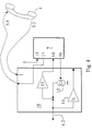
- Figure 4 shows a further embodiment of an inventive Device 18, which is used as an adapter for connecting an additional device 7 serves, but does not contain the additional device 7 itself.
- the components of the adapter and the additional device correspond to those in FIG. 2 shown and are designated by the same reference numerals.
- Adapters 18 can be any commercially available additional devices 7 simple terminal can be connected without it on the part of the Electronics of the additional device and the terminal of a modification requirement.
- the invention is particularly applicable in the field of telecommunications as a modified additional device or as an adapter for connecting a Additional device with which end devices already used are universal can be expanded, advantageously used commercially, which makes one broad customer base the use of new telecommunications features is opened.
Landscapes
- Engineering & Computer Science (AREA)
- Signal Processing (AREA)
- Telephonic Communication Services (AREA)
- Telephone Function (AREA)
- Data Exchanges In Wide-Area Networks (AREA)
- Mobile Radio Communication Systems (AREA)
Applications Claiming Priority (2)
| Application Number | Priority Date | Filing Date | Title |
|---|---|---|---|
| DE19832664 | 1998-07-21 | ||
| DE19832664A DE19832664A1 (de) | 1998-07-21 | 1998-07-21 | Verfahren zur Adaptierung von Zusatzeinrichtungen an eine analoge Endeinrichtung für die Telekommunikation und Vorrichtung dazu |
Publications (3)
| Publication Number | Publication Date |
|---|---|
| EP0975129A2 true EP0975129A2 (fr) | 2000-01-26 |
| EP0975129A3 EP0975129A3 (fr) | 2003-12-10 |
| EP0975129B1 EP0975129B1 (fr) | 2006-03-08 |
Family
ID=7874736
Family Applications (1)
| Application Number | Title | Priority Date | Filing Date |
|---|---|---|---|
| EP99110117A Expired - Lifetime EP0975129B1 (fr) | 1998-07-21 | 1999-05-25 | Dispositif et méthode pour adapter des appareils accessoires à un terminal analogique de télécommunication |
Country Status (5)
| Country | Link |
|---|---|
| US (1) | US6636601B1 (fr) |
| EP (1) | EP0975129B1 (fr) |
| JP (1) | JP2000078244A (fr) |
| AT (1) | ATE320136T1 (fr) |
| DE (2) | DE19832664A1 (fr) |
Cited By (1)
| Publication number | Priority date | Publication date | Assignee | Title |
|---|---|---|---|---|
| EP1294160A3 (fr) * | 2001-09-14 | 2004-02-04 | Mitel Knowledge Corporation | Système de signalisation |
Families Citing this family (1)
| Publication number | Priority date | Publication date | Assignee | Title |
|---|---|---|---|---|
| CN101909124B (zh) * | 2009-06-08 | 2012-07-04 | 亚旭电脑股份有限公司 | 网络电话机 |
Family Cites Families (11)
| Publication number | Priority date | Publication date | Assignee | Title |
|---|---|---|---|---|
| US5151972A (en) * | 1989-03-28 | 1992-09-29 | Lynx Automation, Inc. | Apparatus for automatically connecting terminal device to telephone lines |
| US5206898A (en) * | 1989-05-26 | 1993-04-27 | Shirohato Yakuhiin Co., Ltd. | Transmission control unit |
| US5473676A (en) * | 1990-09-27 | 1995-12-05 | Radish Communications Systems, Inc. | Telephone handset interface for automatic switching between voice and data communications |
| DE4206933A1 (de) * | 1992-03-05 | 1993-09-09 | Teleint Ges Fuer Computer Und | Fernsprecheinrichtung |
| DE4207291A1 (de) * | 1992-03-07 | 1993-09-09 | Bundesrep Deutschland | Anordnung zur anschaltung von zusatzgeraeten an ein telefon |
| US5455859A (en) * | 1994-11-28 | 1995-10-03 | Gutzmer; Howard A. | Telephone handset interface for device having audio input |
| JPH08298585A (ja) * | 1995-04-26 | 1996-11-12 | Oki Data:Kk | 通信端末の切り換え制御装置 |
| DE19529200A1 (de) * | 1995-08-09 | 1997-02-13 | Grundig Emv | Verfahren und Schaltungsanordnung zur automatischen Erkennung des Belegungszustandes einer Telekommunikationsleitung |
| DE19606148A1 (de) * | 1996-02-16 | 1997-09-11 | Insys Gmbh | Telefonleitungsanschaltung |
| US5625679A (en) * | 1996-04-23 | 1997-04-29 | Gutzmer Enterprises, Ltd. | Telephone handset interface for alternating voice-data (AVD) modem |
| US5912948A (en) * | 1996-12-10 | 1999-06-15 | Vertizon Corporation | Automatic screening apparatus and method for use with telephone answering devices |
-
1998
- 1998-07-21 DE DE19832664A patent/DE19832664A1/de not_active Withdrawn
-
1999
- 1999-05-25 AT AT99110117T patent/ATE320136T1/de not_active IP Right Cessation
- 1999-05-25 EP EP99110117A patent/EP0975129B1/fr not_active Expired - Lifetime
- 1999-05-25 DE DE59913184T patent/DE59913184D1/de not_active Expired - Lifetime
- 1999-07-15 JP JP11201616A patent/JP2000078244A/ja active Pending
- 1999-07-21 US US09/358,313 patent/US6636601B1/en not_active Expired - Lifetime
Cited By (2)
| Publication number | Priority date | Publication date | Assignee | Title |
|---|---|---|---|---|
| EP1294160A3 (fr) * | 2001-09-14 | 2004-02-04 | Mitel Knowledge Corporation | Système de signalisation |
| US7536004B2 (en) | 2001-09-14 | 2009-05-19 | Mitel Networks Corporation | Signaling system |
Also Published As
| Publication number | Publication date |
|---|---|
| EP0975129A3 (fr) | 2003-12-10 |
| US6636601B1 (en) | 2003-10-21 |
| DE19832664A1 (de) | 2000-01-27 |
| DE59913184D1 (de) | 2006-05-04 |
| EP0975129B1 (fr) | 2006-03-08 |
| JP2000078244A (ja) | 2000-03-14 |
| ATE320136T1 (de) | 2006-03-15 |
Similar Documents
| Publication | Publication Date | Title |
|---|---|---|
| DE69428068T2 (de) | Teilnehmerschnittstellenschaltung | |
| DE3407982C2 (de) | Übertragerlose Teilnehmerschaltung | |
| DE19848588B4 (de) | Nichtlinearer Prozessor für akustische Echokompensatoren | |
| DE4136138A1 (de) | Multifunktionales telefonsystem mit spracherkennungs- und auswerteeinrichtung sowie ein verfahren zum betrieb dieses telefonsystems | |
| DE69310507T2 (de) | Breitband teilnehmerleitungsschnittstelleschaltung | |
| DE3618896C2 (fr) | ||
| DE69305739T2 (de) | Teilnehmerleitungsschnittstelle mit spannungsgesteuerter schleifenstromeinstellung | |
| DE69014968T2 (de) | Bildschirmtextantwortendgerät. | |
| EP0975129B1 (fr) | Dispositif et méthode pour adapter des appareils accessoires à un terminal analogique de télécommunication | |
| DE60028226T2 (de) | Verfahren und anordnung zur gleichspannungsspeisungssteuerung | |
| EP0942620B1 (fr) | Méthode d'initialisation d'un dispositif de terminaison de réseau pour la connexion avec un réseau de communication numérique ou analogue | |
| DE69632284T2 (de) | Fernzugangsvorrichtung zu einem virtuellen Privatnetz | |
| EP0720340A2 (fr) | Méthode d'interception d'appels téléphoniques en réception | |
| EP0557778B1 (fr) | Système de télécommunication avec un interphone à mains libre | |
| DE69634718T2 (de) | Kommunikationseinrichtung mit Verwenund einer Telefonleitung | |
| DE69119279T2 (de) | Geteiltes Faksimile-Telefon-Kommunikationsgerät | |
| DE20202790U1 (de) | Von mehreren Kommunikationsgeräten gemeinsam verwendbare Freihandeinrichtung | |
| DE602005001352T2 (de) | Verfahren zum Testen einer Teilnehmerleitungsschnittstelle, welche eine Hybridschaltung enthält, und entsprechende Vorrichtung | |
| DE2741160C2 (de) | Schaltungsanordnung für eine Ruf-, Türwechselsprech- und Türöffneranlage | |
| DE2236266B2 (de) | Anordnung zur Feststellung von Signalen in Form von Erdkriterien, die über die Sprechadern einer Fernsprechleitung übertragen werden | |
| DE4141887C1 (fr) | ||
| EP0749654B1 (fr) | Telephone compact | |
| DE69026095T2 (de) | Kopplungseinrichtung zum Anschluss einer Datenübertragungs- anschu-einrichtung an verschiedene öffentliche Fernsprechwahlnetzen sowie eine Datenübertragungsanschlu-einrichtung und eine Arbeitsstation mit einer solchen Kopplungseinrichtung | |
| DE10017413C2 (de) | Verfahren und Anordnung zur Bestimmung des Gabelstatus bei einem Telefongerät | |
| DE2505811C3 (de) | Schaltungsanordnung für eine sprachgesteuerte Gegensprechanlage |
Legal Events
| Date | Code | Title | Description |
|---|---|---|---|
| PUAI | Public reference made under article 153(3) epc to a published international application that has entered the european phase |
Free format text: ORIGINAL CODE: 0009012 |
|
| AK | Designated contracting states |
Kind code of ref document: A2 Designated state(s): AT BE CH CY DE DK ES FI FR GB GR IE IT LI LU MC NL PT SE |
|
| AX | Request for extension of the european patent |
Free format text: AL;LT;LV;MK;RO;SI |
|
| PUAL | Search report despatched |
Free format text: ORIGINAL CODE: 0009013 |
|
| AK | Designated contracting states |
Kind code of ref document: A3 Designated state(s): AT BE CH CY DE DK ES FI FR GB GR IE IT LI LU MC NL PT SE |
|
| AX | Request for extension of the european patent |
Extension state: AL LT LV MK RO SI |
|
| RIC1 | Information provided on ipc code assigned before grant |
Ipc: 7H 04M 1/215 B Ipc: 7H 04M 1/00 A |
|
| 17P | Request for examination filed |
Effective date: 20040611 |
|
| AKX | Designation fees paid |
Designated state(s): AT BE CH CY DE DK ES FI FR GB GR IE IT LI LU MC NL PT SE |
|
| 17Q | First examination report despatched |
Effective date: 20041213 |
|
| GRAP | Despatch of communication of intention to grant a patent |
Free format text: ORIGINAL CODE: EPIDOSNIGR1 |
|
| GRAS | Grant fee paid |
Free format text: ORIGINAL CODE: EPIDOSNIGR3 |
|
| GRAA | (expected) grant |
Free format text: ORIGINAL CODE: 0009210 |
|
| AK | Designated contracting states |
Kind code of ref document: B1 Designated state(s): AT BE CH CY DE DK ES FI FR GB GR IE IT LI LU MC NL PT SE |
|
| PG25 | Lapsed in a contracting state [announced via postgrant information from national office to epo] |
Ref country code: NL Free format text: LAPSE BECAUSE OF FAILURE TO SUBMIT A TRANSLATION OF THE DESCRIPTION OR TO PAY THE FEE WITHIN THE PRESCRIBED TIME-LIMIT Effective date: 20060308 Ref country code: IT Free format text: LAPSE BECAUSE OF FAILURE TO SUBMIT A TRANSLATION OF THE DESCRIPTION OR TO PAY THE FEE WITHIN THE PRESCRIBED TIME-LIMIT;WARNING: LAPSES OF ITALIAN PATENTS WITH EFFECTIVE DATE BEFORE 2007 MAY HAVE OCCURRED AT ANY TIME BEFORE 2007. THE CORRECT EFFECTIVE DATE MAY BE DIFFERENT FROM THE ONE RECORDED. Effective date: 20060308 Ref country code: IE Free format text: LAPSE BECAUSE OF FAILURE TO SUBMIT A TRANSLATION OF THE DESCRIPTION OR TO PAY THE FEE WITHIN THE PRESCRIBED TIME-LIMIT Effective date: 20060308 Ref country code: GB Free format text: LAPSE BECAUSE OF FAILURE TO SUBMIT A TRANSLATION OF THE DESCRIPTION OR TO PAY THE FEE WITHIN THE PRESCRIBED TIME-LIMIT Effective date: 20060308 Ref country code: FI Free format text: LAPSE BECAUSE OF FAILURE TO SUBMIT A TRANSLATION OF THE DESCRIPTION OR TO PAY THE FEE WITHIN THE PRESCRIBED TIME-LIMIT Effective date: 20060308 |
|
| REG | Reference to a national code |
Ref country code: GB Ref legal event code: FG4D Free format text: NOT ENGLISH |
|
| REG | Reference to a national code |
Ref country code: CH Ref legal event code: EP |
|
| REG | Reference to a national code |
Ref country code: IE Ref legal event code: FG4D Free format text: LANGUAGE OF EP DOCUMENT: GERMAN |
|
| REF | Corresponds to: |
Ref document number: 59913184 Country of ref document: DE Date of ref document: 20060504 Kind code of ref document: P |
|
| PG25 | Lapsed in a contracting state [announced via postgrant information from national office to epo] |
Ref country code: AT Free format text: LAPSE BECAUSE OF NON-PAYMENT OF DUE FEES Effective date: 20060525 |
|
| PG25 | Lapsed in a contracting state [announced via postgrant information from national office to epo] |
Ref country code: MC Free format text: LAPSE BECAUSE OF NON-PAYMENT OF DUE FEES Effective date: 20060531 Ref country code: LI Free format text: LAPSE BECAUSE OF NON-PAYMENT OF DUE FEES Effective date: 20060531 Ref country code: CH Free format text: LAPSE BECAUSE OF NON-PAYMENT OF DUE FEES Effective date: 20060531 Ref country code: BE Free format text: LAPSE BECAUSE OF NON-PAYMENT OF DUE FEES Effective date: 20060531 |
|
| PG25 | Lapsed in a contracting state [announced via postgrant information from national office to epo] |
Ref country code: SE Free format text: LAPSE BECAUSE OF FAILURE TO SUBMIT A TRANSLATION OF THE DESCRIPTION OR TO PAY THE FEE WITHIN THE PRESCRIBED TIME-LIMIT Effective date: 20060608 Ref country code: DK Free format text: LAPSE BECAUSE OF FAILURE TO SUBMIT A TRANSLATION OF THE DESCRIPTION OR TO PAY THE FEE WITHIN THE PRESCRIBED TIME-LIMIT Effective date: 20060608 |
|
| PG25 | Lapsed in a contracting state [announced via postgrant information from national office to epo] |
Ref country code: ES Free format text: LAPSE BECAUSE OF FAILURE TO SUBMIT A TRANSLATION OF THE DESCRIPTION OR TO PAY THE FEE WITHIN THE PRESCRIBED TIME-LIMIT Effective date: 20060619 |
|
| PG25 | Lapsed in a contracting state [announced via postgrant information from national office to epo] |
Ref country code: PT Free format text: LAPSE BECAUSE OF FAILURE TO SUBMIT A TRANSLATION OF THE DESCRIPTION OR TO PAY THE FEE WITHIN THE PRESCRIBED TIME-LIMIT Effective date: 20060808 |
|
| NLV1 | Nl: lapsed or annulled due to failure to fulfill the requirements of art. 29p and 29m of the patents act | ||
| GBV | Gb: ep patent (uk) treated as always having been void in accordance with gb section 77(7)/1977 [no translation filed] |
Effective date: 20060308 |
|
| REG | Reference to a national code |
Ref country code: IE Ref legal event code: FD4D |
|
| PLBE | No opposition filed within time limit |
Free format text: ORIGINAL CODE: 0009261 |
|
| STAA | Information on the status of an ep patent application or granted ep patent |
Free format text: STATUS: NO OPPOSITION FILED WITHIN TIME LIMIT |
|
| REG | Reference to a national code |
Ref country code: CH Ref legal event code: PL |
|
| 26N | No opposition filed |
Effective date: 20061211 |
|
| EN | Fr: translation not filed | ||
| BERE | Be: lapsed |
Owner name: DEUTSCHE TELEKOM A.G. Effective date: 20060531 |
|
| PG25 | Lapsed in a contracting state [announced via postgrant information from national office to epo] |
Ref country code: GR Free format text: LAPSE BECAUSE OF FAILURE TO SUBMIT A TRANSLATION OF THE DESCRIPTION OR TO PAY THE FEE WITHIN THE PRESCRIBED TIME-LIMIT Effective date: 20060609 Ref country code: FR Free format text: LAPSE BECAUSE OF FAILURE TO SUBMIT A TRANSLATION OF THE DESCRIPTION OR TO PAY THE FEE WITHIN THE PRESCRIBED TIME-LIMIT Effective date: 20070309 |
|
| PG25 | Lapsed in a contracting state [announced via postgrant information from national office to epo] |
Ref country code: LU Free format text: LAPSE BECAUSE OF NON-PAYMENT OF DUE FEES Effective date: 20060525 |
|
| PG25 | Lapsed in a contracting state [announced via postgrant information from national office to epo] |
Ref country code: FR Free format text: LAPSE BECAUSE OF FAILURE TO SUBMIT A TRANSLATION OF THE DESCRIPTION OR TO PAY THE FEE WITHIN THE PRESCRIBED TIME-LIMIT Effective date: 20060531 |
|
| PG25 | Lapsed in a contracting state [announced via postgrant information from national office to epo] |
Ref country code: FR Free format text: LAPSE BECAUSE OF FAILURE TO SUBMIT A TRANSLATION OF THE DESCRIPTION OR TO PAY THE FEE WITHIN THE PRESCRIBED TIME-LIMIT Effective date: 20060308 Ref country code: CY Free format text: LAPSE BECAUSE OF FAILURE TO SUBMIT A TRANSLATION OF THE DESCRIPTION OR TO PAY THE FEE WITHIN THE PRESCRIBED TIME-LIMIT Effective date: 20060308 |
|
| PGFP | Annual fee paid to national office [announced via postgrant information from national office to epo] |
Ref country code: DE Payment date: 20160525 Year of fee payment: 18 |
|
| REG | Reference to a national code |
Ref country code: DE Ref legal event code: R119 Ref document number: 59913184 Country of ref document: DE |
|
| PG25 | Lapsed in a contracting state [announced via postgrant information from national office to epo] |
Ref country code: DE Free format text: LAPSE BECAUSE OF NON-PAYMENT OF DUE FEES Effective date: 20171201 |