EP0975456B1 - Dispositif pour couper de l'ail - Google Patents
Dispositif pour couper de l'ail Download PDFInfo
- Publication number
- EP0975456B1 EP0975456B1 EP99902543A EP99902543A EP0975456B1 EP 0975456 B1 EP0975456 B1 EP 0975456B1 EP 99902543 A EP99902543 A EP 99902543A EP 99902543 A EP99902543 A EP 99902543A EP 0975456 B1 EP0975456 B1 EP 0975456B1
- Authority
- EP
- European Patent Office
- Prior art keywords
- garlic
- spindle
- union nut
- plunger
- cutter according
- Prior art date
- Legal status (The legal status is an assumption and is not a legal conclusion. Google has not performed a legal analysis and makes no representation as to the accuracy of the status listed.)
- Expired - Lifetime
Links
- 235000004611 garlic Nutrition 0.000 title claims abstract description 53
- 244000245420 ail Species 0.000 title 1
- 240000002234 Allium sativum Species 0.000 claims abstract description 52
- 238000004140 cleaning Methods 0.000 claims description 7
- 238000006073 displacement reaction Methods 0.000 claims description 2
- 241000234282 Allium Species 0.000 description 11
- 235000002732 Allium cepa var. cepa Nutrition 0.000 description 11
- 235000013399 edible fruits Nutrition 0.000 description 8
- 244000223014 Syzygium aromaticum Species 0.000 description 5
- 235000016639 Syzygium aromaticum Nutrition 0.000 description 5
- 210000001331 nose Anatomy 0.000 description 3
- 238000003825 pressing Methods 0.000 description 3
- 235000013580 sausages Nutrition 0.000 description 3
- 235000013311 vegetables Nutrition 0.000 description 3
- 230000000694 effects Effects 0.000 description 2
- 230000007246 mechanism Effects 0.000 description 2
- 239000002184 metal Substances 0.000 description 2
- 230000008901 benefit Effects 0.000 description 1
- 239000003795 chemical substances by application Substances 0.000 description 1
- 230000006835 compression Effects 0.000 description 1
- 238000007906 compression Methods 0.000 description 1
- 238000005516 engineering process Methods 0.000 description 1
- 210000003746 feather Anatomy 0.000 description 1
- 238000007654 immersion Methods 0.000 description 1
- 238000003780 insertion Methods 0.000 description 1
- 230000037431 insertion Effects 0.000 description 1
- 230000003993 interaction Effects 0.000 description 1
- 230000007257 malfunction Effects 0.000 description 1
- 238000000034 method Methods 0.000 description 1
- 230000035515 penetration Effects 0.000 description 1
- 230000008569 process Effects 0.000 description 1
Images


Classifications
-
- B—PERFORMING OPERATIONS; TRANSPORTING
- B26—HAND CUTTING TOOLS; CUTTING; SEVERING
- B26D—CUTTING; DETAILS COMMON TO MACHINES FOR PERFORATING, PUNCHING, CUTTING-OUT, STAMPING-OUT OR SEVERING
- B26D3/00—Cutting work characterised by the nature of the cut made; Apparatus therefor
- B26D3/24—Cutting work characterised by the nature of the cut made; Apparatus therefor to obtain segments other than slices, e.g. cutting pies
- B26D3/26—Cutting work characterised by the nature of the cut made; Apparatus therefor to obtain segments other than slices, e.g. cutting pies specially adapted for cutting fruit or vegetables, e.g. for onions
-
- B—PERFORMING OPERATIONS; TRANSPORTING
- B26—HAND CUTTING TOOLS; CUTTING; SEVERING
- B26D—CUTTING; DETAILS COMMON TO MACHINES FOR PERFORATING, PUNCHING, CUTTING-OUT, STAMPING-OUT OR SEVERING
- B26D7/00—Details of apparatus for cutting, cutting-out, stamping-out, punching, perforating, or severing by means other than cutting
- B26D7/06—Arrangements for feeding or delivering work of other than sheet, web, or filamentary form
- B26D7/0608—Arrangements for feeding or delivering work of other than sheet, web, or filamentary form by pushers
-
- B—PERFORMING OPERATIONS; TRANSPORTING
- B26—HAND CUTTING TOOLS; CUTTING; SEVERING
- B26D—CUTTING; DETAILS COMMON TO MACHINES FOR PERFORATING, PUNCHING, CUTTING-OUT, STAMPING-OUT OR SEVERING
- B26D3/00—Cutting work characterised by the nature of the cut made; Apparatus therefor
- B26D3/18—Cutting work characterised by the nature of the cut made; Apparatus therefor to obtain cubes or the like
-
- Y—GENERAL TAGGING OF NEW TECHNOLOGICAL DEVELOPMENTS; GENERAL TAGGING OF CROSS-SECTIONAL TECHNOLOGIES SPANNING OVER SEVERAL SECTIONS OF THE IPC; TECHNICAL SUBJECTS COVERED BY FORMER USPC CROSS-REFERENCE ART COLLECTIONS [XRACs] AND DIGESTS
- Y10—TECHNICAL SUBJECTS COVERED BY FORMER USPC
- Y10S—TECHNICAL SUBJECTS COVERED BY FORMER USPC CROSS-REFERENCE ART COLLECTIONS [XRACs] AND DIGESTS
- Y10S83/00—Cutting
- Y10S83/929—Particular nature of work or product
- Y10S83/932—Edible
-
- Y—GENERAL TAGGING OF NEW TECHNOLOGICAL DEVELOPMENTS; GENERAL TAGGING OF CROSS-SECTIONAL TECHNOLOGIES SPANNING OVER SEVERAL SECTIONS OF THE IPC; TECHNICAL SUBJECTS COVERED BY FORMER USPC CROSS-REFERENCE ART COLLECTIONS [XRACs] AND DIGESTS
- Y10—TECHNICAL SUBJECTS COVERED BY FORMER USPC
- Y10T—TECHNICAL SUBJECTS COVERED BY FORMER US CLASSIFICATION
- Y10T83/00—Cutting
- Y10T83/647—With means to convey work relative to tool station
- Y10T83/6656—Rectilinear movement only
- Y10T83/6657—Tool opposing pusher
- Y10T83/666—Screw actuated
-
- Y—GENERAL TAGGING OF NEW TECHNOLOGICAL DEVELOPMENTS; GENERAL TAGGING OF CROSS-SECTIONAL TECHNOLOGIES SPANNING OVER SEVERAL SECTIONS OF THE IPC; TECHNICAL SUBJECTS COVERED BY FORMER USPC CROSS-REFERENCE ART COLLECTIONS [XRACs] AND DIGESTS
- Y10—TECHNICAL SUBJECTS COVERED BY FORMER USPC
- Y10T—TECHNICAL SUBJECTS COVERED BY FORMER US CLASSIFICATION
- Y10T83/00—Cutting
- Y10T83/748—With work immobilizer
Definitions
- the invention relates to a garlic cutter accordingly the preamble of claim 1, which, however, as well as Cutters for other vegetables, such as Onions can be, as well as a stamp for use in a Such garlic cutter, such as that from DE 297 13 837 U1 is known.
- a similar onion cutter compared to the onion rotating cutting wires is known from DE-GM 1 750 135.
- From DE-PS 832 051 is a device for crushing Onions, fruit or other goods known to some Housing body that carries a knife on its underside and has an upper part which has a stamp attached thereto has in the operating state when rotating against Axial movement against the rotating body Performs cutting grid.
- This axially adjustable The fruit is stamped by a rotating cutting grid pushed or pressed, being on the exit side of the Cutting grid with corresponding flags or sausages square cross section arise. These parts are then vertically from the knife arranged behind the cutting grid crushed to their longitudinal direction, making cubes of onions arise.
- the Cutting grid divides the fruit into two dimensions, so that Pens or chopsticks are created, which are later used by the knife be crushed into cubes.
- the stamp is designed so that its front is a two-dimensional cutting grid has a corresponding shape, namely from a plurality of pins which consists of the onion pieces through the cutting grid slide.
- the knife is fixed to the housing, while the stamp and the cutting grid are rotatably mounted, preferably so that they are both rotated by a control unit and an axial movement of the punch relative to the spindle generate rotating grids
- a disadvantage of the known devices is that after inserting the Fruit the lid for a long time "empty" over the relatively fine Thread must be turned down until the punch on the Fruit is present. Only then does the actual cutting or Pressing operation. The top also has to be tedious to open be unscrewed. In addition, the one proposed here is off a large number of cones, stamps cumbersome cleanable.
- the object of the invention is a garlic cutter or Like. Propose cutter for vegetables after filling works faster, crushes the fruit gently and at the same time can also be quickly opened and cleaned.
- the Garlic cutter according to the invention has agents which in Operating condition for an engagement of the spindle and the in an open state, a longitudinal displacement of the spindle allow. All mechanisms are suitable as means a clamp or in the manner of an engagement of a piece Counter thread to the spindle can be brought into a loose position, like snap elements made of plastic or metal. As a means a kind of union nut is provided, which is on the housing body can be applied and which, for example by twisting, Elements for engaging in the spindle or for releasing the Spindle brings.
- the opening of the garlic cutter is also done by the Invention significantly accelerated.
- the user only has to the union nut, preferably from its bayonet lock, loosen, which releases the thread from the spindle. Then the spindle can be pulled out together with the union nut become.
- the knife is attached to the bottom of the housing opposite positions of the housing supporting bridge fixed. It is advantageous that the knife is not over the The center of the cutting grid extends beyond something is narrower. Otherwise, the center would always be from Knife covered so that the garlic sausages on the knife or the tip of the knife could cause a malfunction could lead.
- the counter thread is for the spindle is attached to or inside the union nut. This is a simple variant and only requires a few Individual parts.
- the union nut is preferred by means of a Bayonet lock attached to the housing body.
- the housing body preferably has lugs that extend over a few Stand out areas of the perimeter and the other areas of the Leave blank. So the union nut can easily put on and by a short turn, e.g. quarter or One-third rotation can be locked in a conventional manner.
- Other locking mechanisms e.g. screwing on a own thread or plugging on appropriately shaped Opposites are also possible.
- a Circlip arranged in the operating state on the spindle is pressed and moves away from it when open.
- the status "Operation” or “Opening” changes in this way so automatically by turning the union nut on the Lower part of the housing - preferably when screwing into the Bayonet. Operating errors are avoided.
- a this implementation can be easily implemented by that on one of the parts, e.g. on the lower part, on the circumference distributed several, for example three, noses arranged, which are of increasing strength over their course, so that after Tighten the nut of the snap ring over the leaning Levels glides and through the increasing thickness of the noses pressed inwards and thus against the thread of the spindle becomes.
- these sliding surfaces on the Projections for the holder of the union nut provided bayonet catch pieces.
- This protruding parts then perform two functions, namely that Holding and locking the nut as well as that Push the snap ring together, its counter thread in the thread of the spindle is pressed and so the Operating state is reached.
- the is in the housing body rotating inner body easily for cleaning purposes removable.
- the inner body is preferably via locking elements snapped into the housing body and can be cleaned by simply press on the cutting grid or its bottom from below Frame can be detached. So the user can Take out the inner body slightly and attach the attached one Clean the cutting grate.
- the cutting grid is from Inner body easily removable.
- the connection of both parts e.g. via positive spigot that a Allow the two parts to snap together and make it easy To solve. The cleaning of the cutting grid is therefore again simplified.
- this variant removable inner part also the housing body with the Cutting knife easily accessible, cleanable.
- the knife holder with the Knives can be designed to be removable from the housing body, to make cleaning the two parts easier.
- the connection of the two parts is by one Bayonet lock realized, which is arranged so that in the Operating state of the counter pressure acting on the knife into a The knife holder is in the closed position. Since the Garlic cutter, if it is designed for right-handers Has right-hand thread, i.e. the upper part opposite the lower part is turned to the right against the cutting grid it is advisable to press this bayonet lock, the holds the knife holder on the housing holder so that it opened by turning to the left and closed by turning to the right becomes. This will result in accidental opening during cutting prevented.
- the inner body turns Operation against the housing body holding it.
- the Carrying movement to turn the inner body with the stamp can either be done in that the stamp one has a non-round cross-section and thus in a corresponding molded cavity of the inner body or immersed in what is a preferred embodiment that in the inner body Guide grooves for the stamp are arranged while on Stamp guide tabs are provided in these grooves intervention.
- stamp and Inner body With a symmetrical execution of stamp and Inner body is the assembly in different positions possible. With asymmetrical design only in one. Prefers the stamp is square, which creates four different but completely equivalent assembly options for stamps and inner body result.
- the upper part of the Garlic cutter a stop that keeps turning in the working position is prevented when the stamp is already has reached the bottom of the cutting grate. Especially if the stamp pins are already in the holes of the cutting grid immersion is another axial movement of the punch no longer desired compared to the cutting grid. Such a The end stop then prevents the upper part from turning further to the lower part or to the union nut. To in the simplest case there are two on the inside of the upper part Plastic grooves provided with corresponding pins or Interactions and increases on the union nut top Prevent further rotation in order to protect the stamp.
- the End stop should also be designed so that when it is unscrewed, e.g. with a quarter turn, the fully screwed in Stamp takes the union nut with it and opens it.
- the This makes opening the device considerably easier.
- the upper part is simply twisted, e.g. again about the Cams or projections that also act as an end stop against that deep penetration, at the same time a carry-on movement the union nut so that the entire top, i.e. Union nut plus upper part, after about a quarter turn can be removed.
- the advantage of this variant is in that only a turning of the handle part is necessary to open and no more turning on the union nut.
- Another advantageous embodiment of the invention especially for use on the described Garlic cutter applies to the stamp that the Push the clove of garlic through the knife.
- This stamp owns a variety of pins inserted into the openings of the Scheidgitter can reach and preferably in front are formed, as well as a front plate, which is resilient the stamp sits and covers the pens so that the plate together with the front of the pen a closed one Stamp area forms.
- the front plate preferably contains such many holes, as the stamp has pins. Through each a single pin extends through the holes. In Starting position or until the end of the feed movement of the Stamp on the cutting grid is essentially smooth Surface formed.
- the pins are pushed through the holes in the plate and reach through the grating around the garlic to push completely through the cutting grid.
- Compression springs which relieve the plate when the pressure is released bring in the starting position, which in turn the substantially closed stamp area is achieved.
- the closed stamp area ensures on the one hand completely crush the garlic by largely prevents garlic residues in any cavities remain behind, and on the other hand ensures that when cleaning the smooth surface of the stamp cleaned very quickly can be.
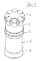
- the garlic cutter according to FIG. 1 has a handle part 1 on which some recessed grips are formed so that the from hand-applied torque can be better introduced.
- the handle part 1 sits on the upper part 2 and is opposite Housing body 6 rotatable.
- On the housing body 6 is the top Union nut 3 attached.
- the housing body 6 goes in below the knife holder 9 over. This is widened to one to form an enlarged footprint.
- the union nut 3 has also a corrugation with hollows to make it easier To ensure handling.
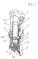
- Figure 2 shows a section of the internal structure of the Garlic cutter. You can see handle 1, upper part 2 and the stamp 12 fastened therein, which is connected to the spindle 4 by the Upper part 2 is attached. These components form a unit.
- the lower part of the device is essentially from Housing body 6 formed, the widened below Knife holder 9 has as a standing surface and on top of which Union nut 3 is screwed on.
- Within the Housing body 6 is rotatable, the inner body 7 on a (not separately shown) metal ring mounted as a sliding element.
- the inner body 7 also set in rotation.
- the knife holder 9 At the bottom of the Inner body 7 is attached to the frame 5a Cutting grid 5b, which is when the punch rotates 12 also rotates. Is fixed relative to the housing body 6 in contrast, the knife holder 9 with the knife 8.
- a snap ring 10 is arranged, the in turn from the retaining ring 11 within the union nut 3 is held.
- Figure 2 shows the garlic cutter according to the invention in State of opening, i.e. the union nut 3 is on the Housing body 6 placed, but not yet locked. Therefore the snap ring 10 is still open and with its Inside, which carries part of a counter thread, still not pressed against the thread of the spindle 4. In this The upper part 2 can be positioned by the spring ring 10 be pulled through without intervening. The operating status is achieved in that the union nut 3 latches, that is is rotated against the housing body 6, whereby the snap ring 10 is compressed and its thread 10a engaged comes with the thread of the spindle 4.
- the union nut 3 again rotated by a short angle, which makes the Snap ring 10 is released, the thread 10a no longer engages in the thread of the spindle 4 and thus the spindle 4 simply pulled out of the lower part or housing body 6 can be.
- the union nut 3 is preferably captive held on the spindle 4 between handle 1 and punch 12.
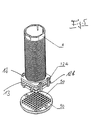
- Figure 3 shows the garlic cutter in the open state.
- the upper part 2 from the handle 1, the upper part 2 with spindle 4 and punch 12, the Union nut 3 lies loosely above the spindle 4, in this but does not intervene.
- the lower part is the housing body 6, the inner body 7 with guide grooves 7a and the cutting grid 5b to see.
- In the upper part 2 is in Sectional view of the end stop 2a can be seen when the Upper part 2 with screw 4 completely screwed down on the Union nut 3 almost comes to rest, with a corresponding Cams or pins within the union nut 3 so in effect occurs that a counter rotation or a further rotation is impossible. This avoids that the stamp 12 to is pressed deep into the cutting grid 5b.
- the stamp 12 has a variety of Pins 13 on which a plate 12b is assigned, so contains many holes, such as pins 13 are present.
- the plate 12b is fastened to the stamp 12 by means of four brackets 12a.
- springs 12c which plate 12b Push away from the punch 12. Only when the plate 12b at the end of Pressing process on the cutting grid 5b, not shown here strikes, the plate 12b is stopped by the grid and against pushed the stamp 12.
- the springs 12c compress pins 12 begin to protrude beyond plate 12b. They extend through the openings of the cutting grid 5b and push the last garlic remnants through the grid against the rotating knife 8 underneath Final state are the top hooks of the clips 12a Stamp 12 lifted off.
- the user opens the Garlic cutter or screw the punch 12 back up, the springs 12c push the plate 12b down again, so that a practically flat surface, formed from the plate 12b and the front of the pins 13 is formed.
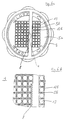
- Figure 5 shows this embodiment of the stamp according to the invention again in a top view.
- the plate 12b is with the Brackets 12a attached to the stamp 12 and is from here springs not shown, of which e.g. five pieces over five Pins 13 seated, pressed down. It can be seen that the number of holes in the cutting grid 5b with the number of pins 13 matches.
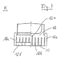
- Figure 6a shows a view from below of the closed Garlic cutter. You can see the knife holder 9 on the housing body 6 by means of a bayonet lock (here Left turn to open) is attached.
- the knife holder 9 carries a footbridge that is just outside the center of the device is arranged, and that over about half its length Knife 8 carries. This knife 8 is fixed during operation the cutting grid 5b with the stamp 12 over during operation the knife 8 turns away.
- the pins 13 can be seen Plate 12b and the frame 5a for the cutting grid 5b.
- Figure 6b shows a detailed picture of the device shown above, wherein again both the knife 8 and the cutting grid 5b can be seen. Likewise, the pins 13 and the plate 12 b.
- Figures 7a and 7b show two sections through the device according to the invention at the level of the union nut 3.
- the upper Part 7a shows the union nut 3 in the operating state.
- the Union nut 3 is with the bayonet catch on the housing body 6 locked, from which the lugs 6a can be seen. These are formed with increasing thickness, so that when twisting the Union nut 3 against the housing body 6 on the lugs 6a accordingly arranged pins of the snap ring 10 act and press it inwards against the spindle 4. This takes effect the thread 10a in the thread of the spindle 4 and leads at Twisting to an axial up and down movement of the punch 12.
- the partial picture 7b shows the union nut 3 in the released state (Opening state).
- the lugs 6a no longer press on the corresponding projections of the snap ring 10. This is through his own elasticity jumped up and expressed his Thread 10a no longer in the thread of the spindle 4. Die Spindle 4 is now from the lower part of the garlic cutter can be pulled out or pushed in easily.
- FIG. 8 finally shows a detail from FIG. 3, namely in a lateral section the engagement of the Thread 10a in the thread of the spindle 4 when the Circlip 10 against the inside by forces Spindle 4 is pressed when it is in the operating position located.
Landscapes
- Life Sciences & Earth Sciences (AREA)
- Forests & Forestry (AREA)
- Engineering & Computer Science (AREA)
- Mechanical Engineering (AREA)
- Food-Manufacturing Devices (AREA)
- Preparation Of Fruits And Vegetables (AREA)
- Apparatuses For Bulk Treatment Of Fruits And Vegetables And Apparatuses For Preparing Feeds (AREA)
- Medicines Containing Plant Substances (AREA)
- Crushing And Pulverization Processes (AREA)
Claims (11)
- Hachoir à ail comprenant un corps formant boítier qui porte un couteau (8) au niveau de son côté inférieur, et une partie supérieure (2) à laquelle est fixé un piston (12) qui, dans l'état de fonctionnement, lorsqu'il tourne par rapport au corps formant boítier (6), exécute un mouvement axial en direction d'une grille de coupe (5b) qui tourne avec lui, un corps intérieur (7) recevant l'ail, qui est monté rotatif dans le corps formant boítier (6), qui présente une grille de coupe (5b) et dans lequel s'enfonce le piston (12) prévu sur une broche (4), caractérisé par des moyens (3) qui, dans l'état de fonctionnement, se chargent de la prise dans la broche (4) tandis que, dans l'état d'ouverture, ils admettent une translation longitudinale de la broche (4) par rapport aux moyens (3), les moyens (3) étant réalisés sous la forme d'un écrou chapeau qui peut être emboíté sur le corps formant boítier (6).
- Hachoir à ail selon la revendication 1, caractérisé par un contre-filetage pour la broche (4) formé dans l'écrou chapeau (3).
- Hachoir à ail selon la revendication 1 ou la revendication 2, caractérisé en ce que l'écrou chapeau (3) peut être fixé au corps formant boítier (6) au moyen d'une fermeture à baïonnette.
- Hachoir à ail selon la revendication 2 ou 3, caractérisé en ce que le contre-filetage est prévu sur le côté intérieur d'un jonc (10) qui est pressé contre la broche dans l'état de fonctionnement et s'en écarte dans l'état d'ouverture.
- Hachoir à ail selon une des revendications précédentes, caractérisé en ce que le corps intérieur (7) peut être retiré pour le nettoyage.
- Hachoir à ail selon une des revendications précédentes, caractérisé en ce que la grille de coupe (5b) est amovible pour le nettoyage du corps intérieur (7).
- Hachoir à ail selon une des revendications précédentes, caractérisé en ce que le couteau (8) est disposé dans un porte-couteau (9) et le porte-couteau (9) est amovible pour le nettoyage du corps formant boítier (6).
- Hachoir à ail selon une des revendications précédentes, caractérisé en ce que le corps intérieur (7) possède des rainures de guidage (7a) pour le piston (12).
- Hachoir à ail selon une des revendications précédentes, caractérisé en ce que la partie supérieure (2) possède une butée de fin de course (2a) qui empêche de continuer à faire tourner la partie supérieure (2), de manière que des tiges du piston (13) disposées sur le piston (12) ne s'engagent pas trop profondément dans la grille de coupe (5b).
- Hachoir à ail selon une des revendications précédentes, caractérisé en ce que la partie supérieure (2) présente une butée de fin de course (2a) qui, lorsqu'on dévisse la partie supérieure (2) dans l'état dans lequel le piston (12) est entièrement vissé, entraíne automatiquement l'écrou chapeau (3).
- Hachoir à ail selon une des revendications précédentes, caractérisé en ce que le piston (12) présente une pluralité de tiges (13) qui peuvent être enfoncés dans les fenêtres de la grille de coupe (5b) et une plaque (12b), qui s'appuie élastiquement sur les tiges (13), de sorte que la plaque (12b) munie des tiges (13) forme une surface de piston pleine.
Priority Applications (2)
| Application Number | Priority Date | Filing Date | Title |
|---|---|---|---|
| EP02016711A EP1252990A1 (fr) | 1998-02-13 | 1999-01-15 | Coupe-légumes, en particulier pour ail |
| SI9930305T SI0975456T1 (en) | 1998-02-13 | 1999-01-15 | Device for chopping garlic |
Applications Claiming Priority (3)
| Application Number | Priority Date | Filing Date | Title |
|---|---|---|---|
| DE19805933A DE19805933C1 (de) | 1998-02-13 | 1998-02-13 | Knoblauchschneider |
| DE19805933 | 1998-02-13 | ||
| PCT/EP1999/000215 WO1999041045A1 (fr) | 1998-02-13 | 1999-01-15 | Dispositif pour couper de l'ail |
Related Child Applications (1)
| Application Number | Title | Priority Date | Filing Date |
|---|---|---|---|
| EP02016711A Division EP1252990A1 (fr) | 1998-02-13 | 1999-01-15 | Coupe-légumes, en particulier pour ail |
Publications (2)
| Publication Number | Publication Date |
|---|---|
| EP0975456A1 EP0975456A1 (fr) | 2000-02-02 |
| EP0975456B1 true EP0975456B1 (fr) | 2003-04-02 |
Family
ID=7857627
Family Applications (2)
| Application Number | Title | Priority Date | Filing Date |
|---|---|---|---|
| EP99902543A Expired - Lifetime EP0975456B1 (fr) | 1998-02-13 | 1999-01-15 | Dispositif pour couper de l'ail |
| EP02016711A Withdrawn EP1252990A1 (fr) | 1998-02-13 | 1999-01-15 | Coupe-légumes, en particulier pour ail |
Family Applications After (1)
| Application Number | Title | Priority Date | Filing Date |
|---|---|---|---|
| EP02016711A Withdrawn EP1252990A1 (fr) | 1998-02-13 | 1999-01-15 | Coupe-légumes, en particulier pour ail |
Country Status (12)
| Country | Link |
|---|---|
| US (1) | US5947016A (fr) |
| EP (2) | EP0975456B1 (fr) |
| JP (1) | JP3210970B2 (fr) |
| KR (1) | KR100346255B1 (fr) |
| CN (1) | CN1167538C (fr) |
| AT (1) | ATE235996T1 (fr) |
| AU (1) | AU735122B2 (fr) |
| CA (1) | CA2286247C (fr) |
| DE (3) | DE19805933C1 (fr) |
| ES (1) | ES2196759T3 (fr) |
| TW (1) | TW396097B (fr) |
| WO (1) | WO1999041045A1 (fr) |
Cited By (1)
| Publication number | Priority date | Publication date | Assignee | Title |
|---|---|---|---|---|
| DE202012003785U1 (de) | 2012-04-13 | 2013-07-17 | Ds Produkte Gmbh | Vorrichtung zum Schneiden von Lebensmitteln |
Families Citing this family (55)
| Publication number | Priority date | Publication date | Assignee | Title |
|---|---|---|---|---|
| DE29811295U1 (de) | 1998-06-25 | 1998-09-03 | Repac, Petra, 65611 Brechen | Knoblauchschneider |
| DE19948168C1 (de) * | 1999-10-07 | 2001-01-11 | Repac Petra | Knoblauchschneider |
| GB2360693A (en) * | 2000-03-28 | 2001-10-03 | Paul Nicholas Wallis | Cucumber shredder |
| US20020175233A1 (en) * | 2001-05-25 | 2002-11-28 | Matt Friedlander | Mobile tire cruncher and method thereof |
| DE20117358U1 (de) | 2001-10-26 | 2002-02-14 | Repac, Petra, 65611 Brechen | Universalreibe zum Verarbeiten von Nahrungsmitteln |
| DE10223075B4 (de) * | 2002-05-24 | 2005-11-24 | Repac, Petra | Gemüseschneider |
| DE10306515B4 (de) * | 2003-02-14 | 2007-07-26 | Repac, Petra | Gemüseschneider, insbesondere Zwiebelschneider |
| US20050028685A1 (en) * | 2003-08-04 | 2005-02-10 | Hajime Yamamoto | Vegetable retainer for vegetable cooking utensil |
| US7086155B2 (en) * | 2004-07-16 | 2006-08-08 | Browne & Co. | Apparatus for coring into and cutting food items |
| DE202004011604U1 (de) * | 2004-07-23 | 2005-01-27 | Eckert, Harald | Vorrichtung zum Zerkleinern von Knoblauch |
| US8186265B2 (en) | 2005-08-08 | 2012-05-29 | Ron's Enterprises, Inc. | Device to efficiently cook food |
| US8850965B2 (en) | 2005-08-08 | 2014-10-07 | Ronald M. Popeil | Device to efficiently cook food |
| US8707857B2 (en) | 2005-08-08 | 2014-04-29 | Ronald M. Popeil | Cooking device to deep fat fry foods |
| US7367519B2 (en) * | 2006-05-12 | 2008-05-06 | Dart Industries Inc. | Processing tool for foodstuffs |
| USD543422S1 (en) | 2006-06-09 | 2007-05-29 | Progressive International Corporation | Vegetable dicer |
| EP2039273B1 (fr) * | 2007-09-20 | 2012-04-11 | So, Kwok Kuen | Dispositif de traitement d'aliments |
| DE202008002233U1 (de) * | 2008-02-18 | 2008-06-12 | Repac, Cedomir | Küchenhobel |
| US8046921B2 (en) * | 2008-03-28 | 2011-11-01 | Focus Products Group, Llc | Apparatus for coring and wedging food items |
| US20090282990A1 (en) * | 2008-05-19 | 2009-11-19 | Farnum Ronald C | Apparatus for cutting food items |
| DE102008053926B4 (de) * | 2008-10-30 | 2014-12-31 | Leifheit Ag | Lebensmittelzerkleinerungsgerät |
| NL2002162C (nl) | 2008-11-03 | 2010-05-04 | Mepal Bv | Knoflookpers. |
| US8677895B2 (en) * | 2008-12-19 | 2014-03-25 | Whirlpool Corporation | Food processor with dicing element |
| US8051769B2 (en) * | 2008-12-19 | 2011-11-08 | Whirpool Corporation | Food processor with cleaning tool |
| US8943954B2 (en) * | 2008-12-19 | 2015-02-03 | Whirlpool Corporation | Food processor with cleaning tool |
| USD632139S1 (en) | 2009-06-10 | 2011-02-08 | Cedomir Repac | Kitchen utensil |
| FR2948053B1 (fr) * | 2009-07-15 | 2011-07-29 | Hameur Sa | Ensemble et procede pour le nettoyage d'une grille |
| USD635410S1 (en) | 2009-11-05 | 2011-04-05 | Cedomir Repac | Combined cutter and grater |
| CN101785636B (zh) * | 2010-01-01 | 2015-05-06 | 王一川 | 大容量手压切挤式蒜泥器 |
| CN101785637B (zh) * | 2010-01-01 | 2015-05-06 | 王一川 | 手摇切挤式碎蒜器 |
| WO2011117874A2 (fr) * | 2010-03-24 | 2011-09-29 | Re-Pet Ltd | Machine à déchiqueter |
| USD670545S1 (en) | 2010-11-16 | 2012-11-13 | Cedomir Repac | Multi-function cutter and grater |
| USD730704S1 (en) | 2011-06-22 | 2015-06-02 | Genius Gmbh | Food cutting device |
| KR101395782B1 (ko) * | 2012-02-24 | 2014-05-15 | 나명운 | 마늘 절단기 |
| USD699507S1 (en) | 2012-03-08 | 2014-02-18 | Grace Manufacturing, Inc. | Culinary tool ram |
| US9119498B2 (en) | 2012-03-08 | 2015-09-01 | Grace Manufacturing, Inc. | Culinary extruding and mincing tool |
| US9439539B2 (en) | 2012-10-18 | 2016-09-13 | Whirlpool Corporation | Dicing tool for domestic food processing device |
| US9622620B2 (en) * | 2012-11-19 | 2017-04-18 | Helen Of Troy Limited | Device for cutting small food items |
| USD734108S1 (en) * | 2013-03-09 | 2015-07-14 | Evriholder Products, Llc | Cupcake corer |
| CN103395091B (zh) * | 2013-08-16 | 2015-07-15 | 阮仕荣 | 微小颗粒制备与分配系统 |
| USD737107S1 (en) | 2014-05-21 | 2015-08-25 | Grace Manufacturing, Inc. | Grater |
| USD761612S1 (en) * | 2014-09-02 | 2016-07-19 | Donald Lee Darnell | Food preparation device |
| USD749918S1 (en) | 2014-09-18 | 2016-02-23 | Grace Manufacturing, Inc. | Culinary tool |
| US20160257015A1 (en) * | 2015-03-05 | 2016-09-08 | Genius Gmbh | Chopping device for cutting foodstuffs, in particular for cutting garlic |
| USD785415S1 (en) | 2016-03-17 | 2017-05-02 | Grace Manufacturing, Inc. | Culinary tool |
| USD799283S1 (en) | 2016-08-04 | 2017-10-10 | Grace Manufacturing, Inc. | Culinary grater |
| USD798676S1 (en) | 2016-08-04 | 2017-10-03 | Grace Manufacturing, Inc. | Culinary grater |
| US10183410B2 (en) * | 2016-09-28 | 2019-01-22 | Progressive International Corporation | Vegetable stick maker |
| US10412981B2 (en) | 2017-02-27 | 2019-09-17 | Ronald M. Popeil | System and method for deep frying poultry while avoiding skin damage |
| CN111390985B (zh) * | 2018-07-23 | 2021-06-01 | 南京溧水高新产业股权投资有限公司 | 一种负压式家用洋葱切片装置及使用方法 |
| CN109156856B (zh) * | 2018-10-31 | 2021-04-27 | 山东青田食品有限公司 | 一种全自动大蒜脱皮机 |
| CN111070269B (zh) * | 2019-11-26 | 2021-06-22 | 徐州工程学院 | 一种食材切片装置 |
| DE102021113525A1 (de) * | 2021-05-26 | 2022-12-01 | Brandivision Gmbh | Vorrichtung zum Pressen |
| US11897157B1 (en) * | 2023-03-15 | 2024-02-13 | Bruce Feldman | Garlic mincer |
| CN116037297B (zh) * | 2023-03-31 | 2023-07-11 | 河北华裕永诚食品有限公司 | 一种脱水蒜高效破碎装置 |
| USD1122677S1 (en) | 2024-02-06 | 2026-04-21 | Grace Manufacturing, Inc. | Culinary tool |
Family Cites Families (23)
| Publication number | Priority date | Publication date | Assignee | Title |
|---|---|---|---|---|
| US343840A (en) * | 1886-06-15 | Vegetable-chopper | ||
| DE131453C (fr) * | ||||
| US533703A (en) * | 1895-02-05 | calla- | ||
| US2500973A (en) * | 1946-04-04 | 1950-03-21 | Ackerman Charles | Slicing machine |
| DE832051C (de) * | 1950-09-29 | 1952-02-21 | Tilo Ufer | Geraet zum Zerkleinern von Zwiebeln, Obst und sonstigem Gut |
| DE1750135A1 (de) * | 1968-04-02 | 1971-01-07 | Philips Patentverwaltung | Vorrichtung mit einem eine Kurvenscheibe abtastenden Tasthebel |
| FR2080059A5 (fr) * | 1970-02-23 | 1971-11-12 | Kyvon Robert De | |
| DE2119992A1 (fr) * | 1971-04-23 | 1972-10-26 | ||
| DE2232672A1 (de) * | 1972-07-04 | 1974-01-24 | Wehner Walter | Vorrichtung zum schneiden von speisezwiebeln |
| US4095518A (en) * | 1976-09-28 | 1978-06-20 | Fasline Food Equipment Co. | Sectioning device for rounded food article |
| US4436025A (en) * | 1983-04-01 | 1984-03-13 | Jones Frank W | Sectioning device for rounded food articles |
| US4579028A (en) * | 1984-08-01 | 1986-04-01 | Neidhardt Edward M | Onion dicer |
| US4569280B1 (en) * | 1984-09-26 | 1996-07-02 | Le Jo Enterprises Inc | Produce wedger |
| US4819882A (en) * | 1988-01-07 | 1989-04-11 | Whirlpool Corporation | Food processor food pusher positioning apparatus |
| DK118991A (da) * | 1991-06-19 | 1992-12-20 | Peter Bindner | Presse til knusning af planteprodukter f.eks. hvidloeg |
| US5216031A (en) * | 1991-07-26 | 1993-06-01 | The West Bend Company | Vegetable cutting device |
| US5121679A (en) * | 1991-11-12 | 1992-06-16 | Mertz Myron M | Potato cutting apparatus |
| JP2543462B2 (ja) * | 1992-05-06 | 1996-10-16 | 株式会社ムロコーポレーション | 果菜の分割切断器 |
| US5271317A (en) * | 1993-03-05 | 1993-12-21 | Aguerrevere Maria S R | Potato slicer device |
| US5337480A (en) * | 1993-05-07 | 1994-08-16 | Ralph Codikow | Subdividing device |
| US5421249A (en) * | 1994-04-28 | 1995-06-06 | Milton Industries, Inc. | Food wedger |
| US5375512A (en) * | 1994-05-31 | 1994-12-27 | Ertmer; Lyle E. | Apparatus to support a fruit or vegetable on a spherical surface and to slice it with a single stroke |
| DE29713837U1 (de) * | 1997-08-02 | 1997-10-09 | Repac, Petra, 65611 Brechen | Knoblauchschneider |
-
1998
- 1998-02-13 DE DE19805933A patent/DE19805933C1/de not_active Expired - Lifetime
- 1998-05-18 DE DE29808989U patent/DE29808989U1/de not_active Expired - Lifetime
- 1998-09-04 US US09/146,756 patent/US5947016A/en not_active Expired - Lifetime
-
1999
- 1999-01-15 EP EP99902543A patent/EP0975456B1/fr not_active Expired - Lifetime
- 1999-01-15 DE DE59904812T patent/DE59904812D1/de not_active Expired - Lifetime
- 1999-01-15 AT AT99902543T patent/ATE235996T1/de active
- 1999-01-15 WO PCT/EP1999/000215 patent/WO1999041045A1/fr not_active Ceased
- 1999-01-15 CA CA002286247A patent/CA2286247C/fr not_active Expired - Lifetime
- 1999-01-15 EP EP02016711A patent/EP1252990A1/fr not_active Withdrawn
- 1999-01-15 CN CNB998001384A patent/CN1167538C/zh not_active Expired - Lifetime
- 1999-01-15 KR KR1019997009218A patent/KR100346255B1/ko not_active Expired - Fee Related
- 1999-01-15 JP JP54095699A patent/JP3210970B2/ja not_active Expired - Fee Related
- 1999-01-15 ES ES99902543T patent/ES2196759T3/es not_active Expired - Lifetime
- 1999-01-15 AU AU22795/99A patent/AU735122B2/en not_active Expired
- 1999-02-10 TW TW088102240A patent/TW396097B/zh not_active IP Right Cessation
Cited By (1)
| Publication number | Priority date | Publication date | Assignee | Title |
|---|---|---|---|---|
| DE202012003785U1 (de) | 2012-04-13 | 2013-07-17 | Ds Produkte Gmbh | Vorrichtung zum Schneiden von Lebensmitteln |
Also Published As
| Publication number | Publication date |
|---|---|
| CN1167538C (zh) | 2004-09-22 |
| DE29808989U1 (de) | 1998-07-30 |
| ES2196759T3 (es) | 2003-12-16 |
| WO1999041045A1 (fr) | 1999-08-19 |
| DE59904812D1 (de) | 2003-05-08 |
| AU2279599A (en) | 1999-08-30 |
| TW396097B (en) | 2000-07-01 |
| KR20010006139A (ko) | 2001-01-26 |
| EP1252990A1 (fr) | 2002-10-30 |
| ATE235996T1 (de) | 2003-04-15 |
| US5947016A (en) | 1999-09-07 |
| DE19805933C1 (de) | 1999-04-15 |
| JP3210970B2 (ja) | 2001-09-25 |
| EP0975456A1 (fr) | 2000-02-02 |
| CA2286247C (fr) | 2002-02-05 |
| AU735122B2 (en) | 2001-06-28 |
| JP2000515439A (ja) | 2000-11-21 |
| CN1256657A (zh) | 2000-06-14 |
| CA2286247A1 (fr) | 1999-08-19 |
| KR100346255B1 (ko) | 2002-07-26 |
| HK1025532A1 (en) | 2000-11-17 |
Similar Documents
| Publication | Publication Date | Title |
|---|---|---|
| EP0975456B1 (fr) | Dispositif pour couper de l'ail | |
| DE19839704C2 (de) | Knoblauchschneider | |
| EP1137518B1 (fr) | Appareil servant a couper de l'ail en des | |
| EP0143103B1 (fr) | Presse à main pour légumes ou fruits | |
| DE2850623C2 (de) | Handgerät zum Mürbmachen von Fleisch | |
| DE10223075A1 (de) | Gemüseschneider | |
| EP2641515A1 (fr) | Découpeur de pulpe de fruit | |
| DE3226789A1 (de) | Kuechengeraet zur herstellung von beefsteaks | |
| EP3082518B1 (fr) | Presse-ail | |
| DE19733551C2 (de) | Knoblauchschneider | |
| WO2016198596A1 (fr) | Système de coupe pour couper des fruits ou des légumes en guirlandes spiralées | |
| DE20117358U1 (de) | Universalreibe zum Verarbeiten von Nahrungsmitteln | |
| DE2302943C3 (de) | Küchengerät mit einer in einen Füllschacht efnschiebbaren Aufnahmebuchse | |
| DE102007034208B3 (de) | Haushaltspresse | |
| EP3287245B1 (fr) | Dispositif de découpe des aliments en dés | |
| DE102013217690A1 (de) | Komponente eines Küchengeräts | |
| DE102005048788A1 (de) | Schneidhilfe und Aufbewahrungsbehälter für Zwiebeln | |
| DE10332598B4 (de) | Obst/Gemüsereibgerät | |
| EP1775081A1 (fr) | Dispositif de coupe des aliments | |
| DE102014107135B3 (de) | Entkernungsgerät | |
| EP4048124A1 (fr) | Presse-ail | |
| DE102017120194A1 (de) | Presse für Gemüse, Früchte und/oder Gewürze, insbesondere Knoblauch | |
| DE202013001176U1 (de) | Vorrichtung zum manuellen Schneiden von Gemüse | |
| DE202019105830U1 (de) | Knoblauchpresse | |
| DE19747007A1 (de) | Schneidvorrichtung zum Zerkleinern von Nahrungsmitteln |
Legal Events
| Date | Code | Title | Description |
|---|---|---|---|
| PUAI | Public reference made under article 153(3) epc to a published international application that has entered the european phase |
Free format text: ORIGINAL CODE: 0009012 |
|
| 17P | Request for examination filed |
Effective date: 19991002 |
|
| AK | Designated contracting states |
Kind code of ref document: A1 Designated state(s): AT CH DE ES FR GB IT LI NL |
|
| AX | Request for extension of the european patent |
Free format text: SI PAYMENT 19991002 |
|
| 17Q | First examination report despatched |
Effective date: 20011001 |
|
| RAP1 | Party data changed (applicant data changed or rights of an application transferred) |
Owner name: REPAC, PETRA |
|
| GRAG | Despatch of communication of intention to grant |
Free format text: ORIGINAL CODE: EPIDOS AGRA |
|
| GRAG | Despatch of communication of intention to grant |
Free format text: ORIGINAL CODE: EPIDOS AGRA |
|
| GRAH | Despatch of communication of intention to grant a patent |
Free format text: ORIGINAL CODE: EPIDOS IGRA |
|
| GRAH | Despatch of communication of intention to grant a patent |
Free format text: ORIGINAL CODE: EPIDOS IGRA |
|
| GRAA | (expected) grant |
Free format text: ORIGINAL CODE: 0009210 |
|
| AK | Designated contracting states |
Designated state(s): AT CH DE ES FR GB IT LI NL |
|
| AX | Request for extension of the european patent |
Extension state: SI |
|
| REG | Reference to a national code |
Ref country code: GB Ref legal event code: FG4D Free format text: NOT ENGLISH |
|
| REG | Reference to a national code |
Ref country code: CH Ref legal event code: EP |
|
| REF | Corresponds to: |
Ref document number: 59904812 Country of ref document: DE Date of ref document: 20030508 Kind code of ref document: P |
|
| REG | Reference to a national code |
Ref country code: CH Ref legal event code: NV Representative=s name: SERONO INTERNATIONAL SA CORPORATE IP DEPARTMENT |
|
| GBT | Gb: translation of ep patent filed (gb section 77(6)(a)/1977) |
Effective date: 20030805 |
|
| REG | Reference to a national code |
Ref country code: ES Ref legal event code: FG2A Ref document number: 2196759 Country of ref document: ES Kind code of ref document: T3 |
|
| ET | Fr: translation filed | ||
| PLBE | No opposition filed within time limit |
Free format text: ORIGINAL CODE: 0009261 |
|
| STAA | Information on the status of an ep patent application or granted ep patent |
Free format text: STATUS: NO OPPOSITION FILED WITHIN TIME LIMIT |
|
| 26N | No opposition filed |
Effective date: 20040105 |
|
| REG | Reference to a national code |
Ref country code: SI Ref legal event code: IF |
|
| REG | Reference to a national code |
Ref country code: CH Ref legal event code: PFA Owner name: REPAC, PETRA Free format text: REPAC, PETRA#FLIEDERWEG 24#65611 BRECHEN (DE) -TRANSFER TO- REPAC, PETRA#FLIEDERWEG 24#65611 BRECHEN (DE) |
|
| REG | Reference to a national code |
Ref country code: DE Ref legal event code: R082 Ref document number: 59904812 Country of ref document: DE |
|
| PGFP | Annual fee paid to national office [announced via postgrant information from national office to epo] |
Ref country code: IT Payment date: 20120126 Year of fee payment: 14 |
|
| REG | Reference to a national code |
Ref country code: DE Ref legal event code: R081 Ref document number: 59904812 Country of ref document: DE Owner name: GENIUS GMBH, DE Free format text: FORMER OWNER: REPAC, PETRA, 65611 BRECHEN, DE Effective date: 20131009 |
|
| PG25 | Lapsed in a contracting state [announced via postgrant information from national office to epo] |
Ref country code: IT Free format text: LAPSE BECAUSE OF NON-PAYMENT OF DUE FEES Effective date: 20130115 |
|
| REG | Reference to a national code |
Ref country code: CH Ref legal event code: PUE Owner name: GENIUS GMBH, DE Free format text: FORMER OWNER: REPAC, PETRA, DE |
|
| REG | Reference to a national code |
Ref country code: GB Ref legal event code: 732E Free format text: REGISTERED BETWEEN 20140612 AND 20140618 |
|
| REG | Reference to a national code |
Ref country code: NL Ref legal event code: SD Effective date: 20140807 |
|
| REG | Reference to a national code |
Ref country code: ES Ref legal event code: PC2A Owner name: GENIUS GMBH Effective date: 20140811 |
|
| REG | Reference to a national code |
Ref country code: FR Ref legal event code: TP Owner name: GENIUS GMBH, DE Effective date: 20140729 Ref country code: SI Ref legal event code: SP73 Owner name: GENIUS GMBH; DE Effective date: 20140714 |
|
| REG | Reference to a national code |
Ref country code: AT Ref legal event code: PC Ref document number: 235996 Country of ref document: AT Kind code of ref document: T Owner name: GENIUS GMBH, DE Effective date: 20150330 |
|
| REG | Reference to a national code |
Ref country code: FR Ref legal event code: PLFP Year of fee payment: 18 |
|
| REG | Reference to a national code |
Ref country code: FR Ref legal event code: PLFP Year of fee payment: 19 |
|
| PGFP | Annual fee paid to national office [announced via postgrant information from national office to epo] |
Ref country code: NL Payment date: 20170119 Year of fee payment: 19 |
|
| PGFP | Annual fee paid to national office [announced via postgrant information from national office to epo] |
Ref country code: CH Payment date: 20170119 Year of fee payment: 19 |
|
| PGFP | Annual fee paid to national office [announced via postgrant information from national office to epo] |
Ref country code: AT Payment date: 20170123 Year of fee payment: 19 |
|
| REG | Reference to a national code |
Ref country code: FR Ref legal event code: PLFP Year of fee payment: 20 |
|
| PGFP | Annual fee paid to national office [announced via postgrant information from national office to epo] |
Ref country code: DE Payment date: 20180122 Year of fee payment: 20 Ref country code: GB Payment date: 20180119 Year of fee payment: 20 Ref country code: ES Payment date: 20180226 Year of fee payment: 20 |
|
| PGFP | Annual fee paid to national office [announced via postgrant information from national office to epo] |
Ref country code: FR Payment date: 20180119 Year of fee payment: 20 |
|
| REG | Reference to a national code |
Ref country code: CH Ref legal event code: PL |
|
| REG | Reference to a national code |
Ref country code: NL Ref legal event code: MM Effective date: 20180201 |
|
| REG | Reference to a national code |
Ref country code: AT Ref legal event code: MM01 Ref document number: 235996 Country of ref document: AT Kind code of ref document: T Effective date: 20180115 |
|
| REG | Reference to a national code |
Ref country code: SI Ref legal event code: KO00 Effective date: 20180925 |
|
| PG25 | Lapsed in a contracting state [announced via postgrant information from national office to epo] |
Ref country code: CH Free format text: LAPSE BECAUSE OF NON-PAYMENT OF DUE FEES Effective date: 20180131 Ref country code: NL Free format text: LAPSE BECAUSE OF NON-PAYMENT OF DUE FEES Effective date: 20180201 Ref country code: AT Free format text: LAPSE BECAUSE OF NON-PAYMENT OF DUE FEES Effective date: 20180115 Ref country code: LI Free format text: LAPSE BECAUSE OF NON-PAYMENT OF DUE FEES Effective date: 20180131 |
|
| REG | Reference to a national code |
Ref country code: DE Ref legal event code: R071 Ref document number: 59904812 Country of ref document: DE |
|
| REG | Reference to a national code |
Ref country code: GB Ref legal event code: PE20 Expiry date: 20190114 |
|
| PG25 | Lapsed in a contracting state [announced via postgrant information from national office to epo] |
Ref country code: GB Free format text: LAPSE BECAUSE OF EXPIRATION OF PROTECTION Effective date: 20190114 |
|
| REG | Reference to a national code |
Ref country code: ES Ref legal event code: FD2A Effective date: 20200902 |
|
| PG25 | Lapsed in a contracting state [announced via postgrant information from national office to epo] |
Ref country code: ES Free format text: LAPSE BECAUSE OF EXPIRATION OF PROTECTION Effective date: 20190116 |