EP0975461B1 - Kunststoffhohlraumstruktur - Google Patents
Kunststoffhohlraumstruktur Download PDFInfo
- Publication number
- EP0975461B1 EP0975461B1 EP98912324A EP98912324A EP0975461B1 EP 0975461 B1 EP0975461 B1 EP 0975461B1 EP 98912324 A EP98912324 A EP 98912324A EP 98912324 A EP98912324 A EP 98912324A EP 0975461 B1 EP0975461 B1 EP 0975461B1
- Authority
- EP
- European Patent Office
- Prior art keywords
- wall
- plastics material
- housing portion
- material housing
- hollow structure
- Prior art date
- Legal status (The legal status is an assumption and is not a legal conclusion. Google has not performed a legal analysis and makes no representation as to the accuracy of the status listed.)
- Expired - Lifetime
Links
Images

Classifications
-
- B—PERFORMING OPERATIONS; TRANSPORTING
- B29—WORKING OF PLASTICS; WORKING OF SUBSTANCES IN A PLASTIC STATE IN GENERAL
- B29C—SHAPING OR JOINING OF PLASTICS; SHAPING OF MATERIAL IN A PLASTIC STATE, NOT OTHERWISE PROVIDED FOR; AFTER-TREATMENT OF THE SHAPED PRODUCTS, e.g. REPAIRING
- B29C65/00—Joining or sealing of preformed parts, e.g. welding of plastics materials; Apparatus therefor
- B29C65/02—Joining or sealing of preformed parts, e.g. welding of plastics materials; Apparatus therefor by heating, with or without pressure
- B29C65/06—Joining or sealing of preformed parts, e.g. welding of plastics materials; Apparatus therefor by heating, with or without pressure using friction, e.g. spin welding
-
- B—PERFORMING OPERATIONS; TRANSPORTING
- B29—WORKING OF PLASTICS; WORKING OF SUBSTANCES IN A PLASTIC STATE IN GENERAL
- B29C—SHAPING OR JOINING OF PLASTICS; SHAPING OF MATERIAL IN A PLASTIC STATE, NOT OTHERWISE PROVIDED FOR; AFTER-TREATMENT OF THE SHAPED PRODUCTS, e.g. REPAIRING
- B29C66/00—General aspects of processes or apparatus for joining preformed parts
- B29C66/01—General aspects dealing with the joint area or with the area to be joined
- B29C66/05—Particular design of joint configurations
- B29C66/10—Particular design of joint configurations particular design of the joint cross-sections
- B29C66/13—Single flanged joints; Fin-type joints; Single hem joints; Edge joints; Interpenetrating fingered joints; Other specific particular designs of joint cross-sections not provided for in groups B29C66/11 - B29C66/12
- B29C66/131—Single flanged joints, i.e. one of the parts to be joined being rigid and flanged in the joint area
- B29C66/1312—Single flange to flange joints, the parts to be joined being rigid
-
- B—PERFORMING OPERATIONS; TRANSPORTING
- B29—WORKING OF PLASTICS; WORKING OF SUBSTANCES IN A PLASTIC STATE IN GENERAL
- B29C—SHAPING OR JOINING OF PLASTICS; SHAPING OF MATERIAL IN A PLASTIC STATE, NOT OTHERWISE PROVIDED FOR; AFTER-TREATMENT OF THE SHAPED PRODUCTS, e.g. REPAIRING
- B29C66/00—General aspects of processes or apparatus for joining preformed parts
- B29C66/01—General aspects dealing with the joint area or with the area to be joined
- B29C66/05—Particular design of joint configurations
- B29C66/301—Three-dimensional joints, i.e. the joined area being substantially non-flat
-
- B—PERFORMING OPERATIONS; TRANSPORTING
- B29—WORKING OF PLASTICS; WORKING OF SUBSTANCES IN A PLASTIC STATE IN GENERAL
- B29C—SHAPING OR JOINING OF PLASTICS; SHAPING OF MATERIAL IN A PLASTIC STATE, NOT OTHERWISE PROVIDED FOR; AFTER-TREATMENT OF THE SHAPED PRODUCTS, e.g. REPAIRING
- B29C66/00—General aspects of processes or apparatus for joining preformed parts
- B29C66/50—General aspects of joining tubular articles; General aspects of joining long products, i.e. bars or profiled elements; General aspects of joining single elements to tubular articles, hollow articles or bars; General aspects of joining several hollow-preforms to form hollow or tubular articles
- B29C66/51—Joining tubular articles, profiled elements or bars; Joining single elements to tubular articles, hollow articles or bars; Joining several hollow-preforms to form hollow or tubular articles
- B29C66/54—Joining several hollow-preforms, e.g. half-shells, to form hollow articles, e.g. for making balls, containers; Joining several hollow-preforms, e.g. half-cylinders, to form tubular articles
-
- B—PERFORMING OPERATIONS; TRANSPORTING
- B29—WORKING OF PLASTICS; WORKING OF SUBSTANCES IN A PLASTIC STATE IN GENERAL
- B29C—SHAPING OR JOINING OF PLASTICS; SHAPING OF MATERIAL IN A PLASTIC STATE, NOT OTHERWISE PROVIDED FOR; AFTER-TREATMENT OF THE SHAPED PRODUCTS, e.g. REPAIRING
- B29C66/00—General aspects of processes or apparatus for joining preformed parts
- B29C66/50—General aspects of joining tubular articles; General aspects of joining long products, i.e. bars or profiled elements; General aspects of joining single elements to tubular articles, hollow articles or bars; General aspects of joining several hollow-preforms to form hollow or tubular articles
- B29C66/51—Joining tubular articles, profiled elements or bars; Joining single elements to tubular articles, hollow articles or bars; Joining several hollow-preforms to form hollow or tubular articles
- B29C66/54—Joining several hollow-preforms, e.g. half-shells, to form hollow articles, e.g. for making balls, containers; Joining several hollow-preforms, e.g. half-cylinders, to form tubular articles
- B29C66/542—Joining several hollow-preforms, e.g. half-shells, to form hollow articles, e.g. for making balls, containers; Joining several hollow-preforms, e.g. half-cylinders, to form tubular articles joining hollow covers or hollow bottoms to open ends of container bodies
-
- F—MECHANICAL ENGINEERING; LIGHTING; HEATING; WEAPONS; BLASTING
- F02—COMBUSTION ENGINES; HOT-GAS OR COMBUSTION-PRODUCT ENGINE PLANTS
- F02M—SUPPLYING COMBUSTION ENGINES IN GENERAL WITH COMBUSTIBLE MIXTURES OR CONSTITUENTS THEREOF
- F02M35/00—Combustion-air cleaners, air intakes, intake silencers, or induction systems specially adapted for, or arranged on, internal-combustion engines
- F02M35/10—Air intakes; Induction systems
- F02M35/10314—Materials for intake systems
- F02M35/10321—Plastics; Composites; Rubbers
-
- F—MECHANICAL ENGINEERING; LIGHTING; HEATING; WEAPONS; BLASTING
- F02—COMBUSTION ENGINES; HOT-GAS OR COMBUSTION-PRODUCT ENGINE PLANTS
- F02M—SUPPLYING COMBUSTION ENGINES IN GENERAL WITH COMBUSTIBLE MIXTURES OR CONSTITUENTS THEREOF
- F02M35/00—Combustion-air cleaners, air intakes, intake silencers, or induction systems specially adapted for, or arranged on, internal-combustion engines
- F02M35/10—Air intakes; Induction systems
- F02M35/1034—Manufacturing and assembling intake systems
- F02M35/10354—Joining multiple sections together
- F02M35/1036—Joining multiple sections together by welding, bonding or the like
-
- F—MECHANICAL ENGINEERING; LIGHTING; HEATING; WEAPONS; BLASTING
- F02—COMBUSTION ENGINES; HOT-GAS OR COMBUSTION-PRODUCT ENGINE PLANTS
- F02M—SUPPLYING COMBUSTION ENGINES IN GENERAL WITH COMBUSTIBLE MIXTURES OR CONSTITUENTS THEREOF
- F02M35/00—Combustion-air cleaners, air intakes, intake silencers, or induction systems specially adapted for, or arranged on, internal-combustion engines
- F02M35/12—Intake silencers ; Sound modulation, transmission or amplification
- F02M35/1255—Intake silencers ; Sound modulation, transmission or amplification using resonance
-
- F—MECHANICAL ENGINEERING; LIGHTING; HEATING; WEAPONS; BLASTING
- F02—COMBUSTION ENGINES; HOT-GAS OR COMBUSTION-PRODUCT ENGINE PLANTS
- F02M—SUPPLYING COMBUSTION ENGINES IN GENERAL WITH COMBUSTIBLE MIXTURES OR CONSTITUENTS THEREOF
- F02M35/00—Combustion-air cleaners, air intakes, intake silencers, or induction systems specially adapted for, or arranged on, internal-combustion engines
- F02M35/12—Intake silencers ; Sound modulation, transmission or amplification
- F02M35/1283—Manufacturing or assembly; Connectors; Fixations
-
- F—MECHANICAL ENGINEERING; LIGHTING; HEATING; WEAPONS; BLASTING
- F05—INDEXING SCHEMES RELATING TO ENGINES OR PUMPS IN VARIOUS SUBCLASSES OF CLASSES F01-F04
- F05C—INDEXING SCHEME RELATING TO MATERIALS, MATERIAL PROPERTIES OR MATERIAL CHARACTERISTICS FOR MACHINES, ENGINES OR PUMPS OTHER THAN NON-POSITIVE-DISPLACEMENT MACHINES OR ENGINES
- F05C2225/00—Synthetic polymers, e.g. plastics; Rubber
- F05C2225/08—Thermoplastics
Definitions
- the invention relates to a method for producing composite plastic cavity structures or a process for their production.
- JP-8-334070 discloses a plastic cavity structure that is divided into several chambers. These chambers are separated from each other by partitions, these in the individual Housing shells are integrated. Therefore, separation joints are created inside the housing, which need to be sealed. In addition, stiffeners in the housing be attached to the higher one created by the partition walls Compensate component weight. Therefore, the manifold disclosed is expensive in the production and its component weight very high.
- an intake manifold in which an insert in intake manifold shells is inserted.
- the intake manifold shells and the insert have mutually corresponding ones Sealing surfaces that are vibration welded together.
- the insert is fixed in the intake manifold.
- the additional creates Insert an additional manufacturing effort, since this part are manufactured got to.
- this part must over the entire corresponding sealing surface be connected to the intake manifold shells, which creates high welding forces.
- the object of the invention is therefore to provide a plastic cavity structure which is inexpensive to manufacture, has the lowest possible weight and is stable.
- this object is achieved by a method solved according to claim 6.
- Claim 1 shows a composite cavity structure according to the invention.
- An advantageous development of the invention provides that in one The method of claim 6, the connecting force by high pressure and / or high frequencies, especially in the ultrasound range.
- the Wall halves arranged substantially transversely to the welding vibration direction are. On the one hand, this makes the cavity structure more stable, on the other hand With this measure it is possible to create labyrinth-like rooms which, for. B. have a sound-absorbing effect.
- At least one wall half has at least one transverse rib, which is particularly advantageous if a transverse wall half with its corresponding other Wall half by means of vibration welding as so-called remote welding is connected.
- the cross rib prevents excessive deflections of the Half of the wall during vibration welding, which makes welding impossible would do.
- the wall half a plastic housing part as a dome-like bulge Plastic housing wall protrudes into the interior of the housing.
- This three-dimensional Formation of the housing wall also increases the strength, so that the Wall in the area to be welded not too large Deflections affect the quality of the weld seam to be provided or makes impossible at all.
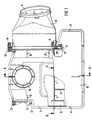
- plastic housing part 3 is shown on the side Filter 5 is arranged, this plastic housing part has wall halves 7 together transverse ribs 8 arranged at right angles thereto, which form the plastic housing part help stabilize.
- the entire one shown in Figure 1 Plastic cavity structure has an inlet 9 and one with it Inlet 9 communicating outlet 10.
- the plastic cavity structure is in the essentially divided into the areas of resonator room 12 and collecting room 13, a filter 5 being arranged in front of the collecting space 13.
- the resonator room 12 communicates with the collecting space 13 by means of a connection opening 14.
- Fastening means 16 are located on the plastic housing part 3, by means of which in connection with screws, not shown in Figure 1, the Plastic cavity structure, which in the variant shown as sound absorbing air intake filter, e.g. not one in the engine compartment shown motor vehicle.
- the plastic housing part 3 so-called vibration welding entrainment ribs 17, the especially in the area of the second one not visible in this illustration Sealing surface are arranged.
- the filter 5 is attached by means of a seal 20 pressed the sealing surface 23 of the plastic housing part 3, which of the lever-shaped housing bracket 21 of the air filter housing 19 in Connection with the threaded bushing 22, which in turn is in the air filter housing 19 located screw 18 receives, the surrounding the screw Housing has a diameter that is smaller than that Thread diameter of the screw 18 so that a self-locking Screw bracket is created, which has advantages in the disassembly and assembly, since the screw 18 does not require any additional effort.
- FIG. 2 shows a section along the line A-A from FIG. 1.
- the Plastic housing part 1 has a first sealing surface 2; the one with the Corresponding plastic housing part 3 and the associated one Sealing surface 4 form the plastic cavity structure.
- the filter of Figure 1 is in this representation is not visible.
- the plastic housing half 1 has one Wall half 6 on, which in turn corresponds to the wall half 7, the Plastic housing part 3 comes from.
- the plastic cavity structure is already an embodiment vibration welded, the transverse ribs 8 to stabilize the far cantilevered wall halves 7 serve to large deflections of the Prevent wall halves 7, since the welding vibration direction 11 in runs essentially at right angles to the wall halves.
- the wall halves 6 are for the same reason in the plastic housing part 3 to increase the strength of the housing part connected by means of dome-like bulges 15. This Dome-like bulges also allow a more direct impact of the Vibration welding tool on the seam surfaces, the dome area Welding experience that can take loads, welding in the area the wall halves 6 perform a sealing function.
- the outlet 10 is in the Plastic housing part housed such that a distance to Housing wall, which is greater than the vibration amplitude, so that it with vibration welding not with the corresponding one Plastic housing part 1 comes into contact.
- the outlet 10 is in contact to the intake tract of the internal combustion engine, not shown, and in turn communicates with that with the resonator chamber 12 communicating collecting space 13 of the plastic cavity structure.
- the Connection between collecting space 13 and resonator space 12 happens by means of a connection opening not visible in this illustration in the Way that the resonator chamber 12 acts as a shunt resonator.
- in the Plastic housing part 1 are for additional stiffening of the housing Stiffening ribs 24 arranged.
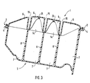
- FIG. 3 shows a section along the line BB from FIG. 1
- Plastic housing part 1 has a first sealing surface 2; the one with the Corresponding plastic housing part 3 and the associated one Sealing surface 4 after vibration welding the plastic cavity structure form.
- the plastic housing half 1 have wall halves 6, which in turn correspond with the wall halves 7 which are in the plastic housing part 3 are attached.
- the cut shown transverse ribs 8 for stabilizing the projecting wall halves 7 serve to deflections of the function impairing the welding Prevent wall halves 7, since the welding vibration direction in runs essentially at right angles to the wall halves (6, 7).
- the wall halves 6 are for the same reason in the plastic housing part 3 to increase the Strength of the housing part connected by means of dome-like bulges 15. These dome-like bulges have a relatively direct impact on the Vibration welding tool possible on the seam surfaces. Not this one visible resonator room communicates with the also not visible Collection space of the plastic cavity structure by means of a connection opening 14. Stiffening ribs 24 are arranged in the plastic cavity structure, that increase the torsional stiffness.
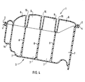
- FIG. 4 shows a section along the line BB from FIG. 1.
- the Plastic housing part 1 has a first sealing surface 2; the one with the Corresponding plastic housing part 3 and the associated one Sealing surface 4 after vibration welding the plastic cavity structure form.
- the plastic housing half 1 have wall halves 6, which in turn correspond with the wall halves 7 which are in the plastic housing part 3 are attached.
- the cut shown transverse ribs 8 for stabilizing the projecting wall halves 7 serve to deflections of the wall halves 7 harmful to the weld prevent since the welding vibration direction is perpendicular to the wall halves (6, 7) runs.
- the wall halves 6 are in the plastic housing part 3 Increasing the strength of the housing part by means of dome-like bulges 15 connected. These dome-like bulges allow a direct one Action of the vibration welding tool on the seam surfaces.
- the not visible resonator room communicates with the invisible collecting room the plastic cavity structure by means of a connection opening 14, which in this embodiment in the form of an independent pipe cross section, the from the plastic housing halves (1, 3) after welding forms, arises.
- a connection opening 14 which in this embodiment in the form of an independent pipe cross section, the from the plastic housing halves (1, 3) after welding forms, arises.
- Stiffening ribs 24 arranged to increase strength.
Landscapes
- Engineering & Computer Science (AREA)
- Mechanical Engineering (AREA)
- Chemical & Material Sciences (AREA)
- Combustion & Propulsion (AREA)
- General Engineering & Computer Science (AREA)
- Manufacturing & Machinery (AREA)
- Lining Or Joining Of Plastics Or The Like (AREA)
Abstract
Description
- Figur 1
- eine Draufsicht eines Ausführungsbeispiels,
- Figur 2
- einen Schnitt entlang der Linie A - A
- Figur 3
- eine Ansicht entlang der Linie B - B
- Figur 4
- eine Ansicht entlang der Linie B - B
Claims (7)
- Zusammengesetzte Hohlraumstruktur, die aus wenigstens zwei Gehäuseteilen (1, 3) mit korrespondierenden Dichtflächen (2, 4) und wenigstens einer Wandhälfte pro Kunststoffgehäuseteil besteht, wobei die Wandhälften zur Verstärkung der Hohlraumstruktur korrespondieren, wobei die die korrespondierenden Dichtflächen (2, 4) und die Wandhälften (6, 7) mittels einer Reibkraft verbunden sind, dadurch gekennzeichnet, daß wenigstens eine Wandhälfte (6) eines Kunststoffgehäuseteiles (1) zur Steigerung der Festigkeit des Gehäuseteils als domartige Ausbuchtung (15) der Kunststoffgehäuseteilwandung ins Gehäuseinnere ragt.
- Zusammengesetzte Hohlraumstruktur, die aus wenigstens zwei Gehäuseteilen (1, 3) mit korrespondierenden Dichtflächen (2, 4) und wenigstens einer Wandhälfte pro Kunststoffgehäuseteil besteht, wobei die Wandhälften zur Verstärkung der Hohlraumstruktur korrespondieren, wobei die die korrespondierenden Dichtflächen (2, 4) und die Wandhälften (6, 7) mittels einer Reibkraft verbunden sind, dadurch gekennzeichnet, daß die Wandhälfte eines Kunststoffgehäuseteiles (3) als Quersteg (7) der Kunststoffgehäuseteilwandung ins Gehäuseinnere ragt und wenigstens ein Quersteg (7) wenigstens eine Querrippe (8) zur Stabilisierung aufweist.
- Zusammengesetzte Hohlraumstruktur nach einem der vorherigen Ansprüche, dadurch gekennzeichnet, daß die Wandhälften (6, 7) im wesentlichen quer zur Schweißvibrationsrichtung (11) angeordnet sind.
- Zusammengesetzte Hohlraumstruktur nach einem der vorherigen Ansprüche , umfassend einen Ein- (9) und einen Auslaß (10), dadurch gekennzeichnet, daß die Wandhälften zur Erzeugung eines im Gehäuseinneren liegenden Resonatorraums korrespondieren, wobei die korrespondierenden Dichtflächen (2,4) und die Wandhälften (6,7) mittels einer Reibkraft verbunden sind und der Einlaß (9), der Resonatorraum (12) und der Auslaß (10) miteinander kommunizieren.
- Luftansaugfilter für eine Brennkraftmaschine (25) mit Schalldämpfung vor und/oder hinter einem Filter (5), dadurch gekennzeichnet, daß eine zusammengesetzte Hohlraumstruktur nach Anspruch 4 zum Einsatz kommt, wobei die Schalldämfung durch den Resonatorraum (12) realisiert ist.
- Verfahren zur Herstellung von zusammengesetzten Kunststoff-Hohlraumstrukturen gemäß einem der vorherigen Ansprüche aus wenigstens zwei Kunststoffgehäuse-Einzelteilen mit korrespondierenden Dicht- (2, 4) und Wandflächen (6, 7) zur Erzeugung von stabilen Hohlraumstrukturen, wobei das Verfahren folgende Schritte umfaßt: Schaffung eines ersten Kunststoffgehäuseteils (1) mit einer ersten Dichtfläche (2) und wenigstens einer ersten Wandhälfte, Schaffung eines zweiten Kunststoffgehäuseteils (3) mit einer zweiten Dichtfläche (4) und wenigstens einer zweiten Wandhälfte, Anbringung des ersten Kunststoffgehäuseteils (1) in einem ersten Werkzeug oder einer Lehre, welches das erste Kunststoffgehäuseteil (1) in der Umgebung der ersten Dichtfläche (2) unterstützt, Anbringung des zweiten Kunststoffgehäuseteils (3) in einem zweiten Werkzeug oder einer Lehre, welches das zweite Kunststoffgehäuseteil (3) in der Umgebung der zweiten Dichtfläche (4) unterstützt, Ausrichten der Teile mit den korrespondierenden Dichtflächen, so daß die korrespondierenden Dichtflächen sowie die wenigstens eine erste Wandhälfte (6) des ersten Kunststoffgehäuseteils (1) und die wenigstens eine zweite Wandhälfte (7) des zweiten Kunststoffgehäuseteils (3) miteinander in Kontakt kommen, Aufbringung einer Verbindungskraft auf die gesamten Dichtflächen, wobei wenigstens eines der Werkzeuge oder Lehren relativ zum anderen Werkzeug bewegt wird, um so eine Reibkraft zum Verbinden der Einzelteile zu erzeugen.
- Verfahren nach Anspruch 6 dadurch gekennzeichnet, daß die Verbindungskraft durch Relativbewegungen und/oder hohe Frequenzen, insbesondere im Ultraschallbereich aufgebracht wird.
Applications Claiming Priority (3)
| Application Number | Priority Date | Filing Date | Title |
|---|---|---|---|
| DE19717196 | 1997-04-24 | ||
| DE19717196A DE19717196A1 (de) | 1997-04-24 | 1997-04-24 | Kunststoffhohlraumstruktur |
| PCT/EP1998/000923 WO1998047690A1 (de) | 1997-04-24 | 1998-02-18 | Kunststoffhohlraumstruktur |
Publications (2)
| Publication Number | Publication Date |
|---|---|
| EP0975461A1 EP0975461A1 (de) | 2000-02-02 |
| EP0975461B1 true EP0975461B1 (de) | 2002-06-12 |
Family
ID=7827530
Family Applications (1)
| Application Number | Title | Priority Date | Filing Date |
|---|---|---|---|
| EP98912324A Expired - Lifetime EP0975461B1 (de) | 1997-04-24 | 1998-02-18 | Kunststoffhohlraumstruktur |
Country Status (6)
| Country | Link |
|---|---|
| US (1) | US6517614B1 (de) |
| EP (1) | EP0975461B1 (de) |
| JP (1) | JP2001521453A (de) |
| DE (2) | DE19717196A1 (de) |
| WO (1) | WO1998047690A1 (de) |
| ZA (1) | ZA982970B (de) |
Cited By (1)
| Publication number | Priority date | Publication date | Assignee | Title |
|---|---|---|---|---|
| DE102004011328A1 (de) * | 2004-03-09 | 2005-09-29 | Mann + Hummel Gmbh | Verbindung zwischen einer Einlegebuchse und einem Rotationsgussformteil |
Families Citing this family (13)
| Publication number | Priority date | Publication date | Assignee | Title |
|---|---|---|---|---|
| US6862622B2 (en) * | 1998-07-10 | 2005-03-01 | Van Drebbel Mariner Llc | Transmission control protocol/internet protocol (TCP/IP) packet-centric wireless point to multi-point (PTMP) transmission system architecture |
| US6452915B1 (en) | 1998-07-10 | 2002-09-17 | Malibu Networks, Inc. | IP-flow classification in a wireless point to multi-point (PTMP) transmission system |
| DE19951408A1 (de) * | 1999-10-26 | 2001-05-03 | Mann & Hummel Filter | Ansaugsystem mit Luftfilter |
| DE10028963A1 (de) * | 2000-06-10 | 2001-12-13 | Mann & Hummel Filter | Ansaugsystem für Brennkraftmaschinen |
| DE10211875A1 (de) * | 2002-03-18 | 2003-10-02 | Mann & Hummel Filter | Verfahren zum Vibrationsschweissen und Werkzeug zu dessen Durchführung |
| DE10216175C1 (de) * | 2002-04-12 | 2003-07-24 | Stiebel Eltron Gmbh & Co Kg | Bauteil, insbesondere Behälter oder Rohr, und Verfahren zur Herstellung eines Behälters |
| US20050150718A1 (en) * | 2004-01-09 | 2005-07-14 | Knight Jessie A. | Resonator with retention ribs |
| JP4436148B2 (ja) * | 2004-02-09 | 2010-03-24 | 本田技研工業株式会社 | 圧力容器用ライナおよびその製造方法 |
| US7141101B2 (en) * | 2004-06-17 | 2006-11-28 | Home Health Medical Equipment Incorporated | Filter assembly with noise attenuation |
| DE102005010204B4 (de) * | 2005-03-05 | 2010-07-22 | Stiebel Eltron Gmbh & Co. Kg | Bauteil zur Aufnahme und/oder Leitung eines Fluids, Verfahren zur Herstellung eines Bauteils |
| JP5685422B2 (ja) * | 2010-11-19 | 2015-03-18 | 本田技研工業株式会社 | コージェネレーション装置 |
| JP2013108381A (ja) * | 2011-11-18 | 2013-06-06 | Honda Motor Co Ltd | 吸気マニホールド |
| US9624877B2 (en) * | 2013-11-14 | 2017-04-18 | Mann+Hummel Gmbh | Elongated tubular hydrocarbon adsorption trap produced from a circularly wrapped sheet media |
Family Cites Families (28)
| Publication number | Priority date | Publication date | Assignee | Title |
|---|---|---|---|---|
| US2906370A (en) * | 1957-08-08 | 1959-09-29 | Gen Motors Corp | Air cleaner and silencer assembly |
| FR1216783A (fr) * | 1960-09-27 | 1960-04-27 | Fram Corp | Filtre à liquides |
| JPS5121212Y2 (de) * | 1971-10-14 | 1976-06-02 | ||
| US3932153A (en) * | 1974-02-14 | 1976-01-13 | John Byrns | Nebulizer bacteria filter |
| GB2067128A (en) * | 1980-01-04 | 1981-07-22 | Banarse P S | Improvements in or relating to the manufacture of plastics bodies |
| GB2109680A (en) * | 1981-09-23 | 1983-06-08 | Florida Plastics Limited | Improvements in or relating to hollow moulded articles |
| DE3341697A1 (de) * | 1983-11-18 | 1985-05-30 | Basf Ag, 6700 Ludwigshafen | Verfahren und vorrichtung zum befestigen von einbauteilen in hohlkoerpern aus thermoplastischen kunststoffen |
| US4685472A (en) * | 1984-01-23 | 1987-08-11 | Rudolph Muto | Specimen collector |
| US4601768A (en) * | 1984-05-11 | 1986-07-22 | Hydroacoustics, Inc. | Method and apparatus for treating plastic welds to relieve stresses therein |
| DE3700981A1 (de) * | 1987-01-15 | 1988-07-28 | Geiger Plastic Verwaltung | Verfahren fuer die verbindung von teilen aus polyamid durch friktionsschweissen |
| DE3712275A1 (de) * | 1987-04-10 | 1988-10-27 | Alois Ferch | Durch ultraschallschweissen zu einem hohlkoerper verbindbare kunststoff-hohlkoerperteile |
| US5342268A (en) * | 1987-09-14 | 1994-08-30 | Dar Products Corporation | Exercise devices |
| JP2517526Y2 (ja) * | 1988-05-23 | 1996-11-20 | スズキ株式会社 | 車両用エアクリーナ |
| US5290445A (en) * | 1988-05-27 | 1994-03-01 | Pall Corporation | Filtering apparatus |
| BE1003470A3 (nl) | 1988-11-09 | 1992-03-31 | Bekaert Sa Nv | Kokerleiding. |
| US4997500A (en) * | 1989-08-28 | 1991-03-05 | At&T Bell Laboratories | Method for joining thermoplastic parts |
| DE4218396B4 (de) * | 1992-06-04 | 2004-04-01 | Mann + Hummel Gmbh | Filtereinrichtung, insbesondere zum Filtrieren der Ansaugluft eines Verbrennungsmotors |
| DE4320384A1 (de) * | 1993-06-19 | 1994-12-22 | Mann & Hummel Filter | Aktivkohlefilter zur Kraftstofftankentlüftung |
| JP3519107B2 (ja) * | 1993-09-24 | 2004-04-12 | ヤマハマリン株式会社 | 船外機の消音装置 |
| US5503662A (en) * | 1994-03-29 | 1996-04-02 | Multiform Desiccants, Inc. | Canister with porous plastic ends |
| DE4437677C2 (de) * | 1994-10-21 | 1997-12-04 | Mann & Hummel Filter | Verfahren zur Herstellung von Saugrohren und Saugrohr aus Kunststoff |
| US5575247A (en) * | 1995-02-01 | 1996-11-19 | Nippondenso Co., Ltd. | Air intake device for an internal combustion engine |
| JP3428778B2 (ja) * | 1995-06-07 | 2003-07-22 | 株式会社デンソー | 内燃機関の吸気装置 |
| DE19508921A1 (de) * | 1995-03-11 | 1996-09-12 | Mann & Hummel Filter | Kunststoffgehäuse |
| DE19614313B4 (de) * | 1995-06-07 | 2006-08-10 | Volkswagen Ag | Saugrohranlage einer Brennkraftmaschine |
| US5857224A (en) * | 1997-10-14 | 1999-01-12 | Sloan Valve Company | Pressure flush tank for use in a toilet enclosure |
| JPH11170388A (ja) * | 1997-12-11 | 1999-06-29 | Kioritz Corp | 二槽タンク及びその製造方法 |
| US6167862B1 (en) * | 1999-05-12 | 2001-01-02 | Siemens Canada Limited | Air cleaner system |
-
1997
- 1997-04-24 DE DE19717196A patent/DE19717196A1/de not_active Withdrawn
-
1998
- 1998-02-18 JP JP54478998A patent/JP2001521453A/ja active Pending
- 1998-02-18 WO PCT/EP1998/000923 patent/WO1998047690A1/de not_active Ceased
- 1998-02-18 DE DE59804427T patent/DE59804427D1/de not_active Expired - Fee Related
- 1998-02-18 US US09/403,544 patent/US6517614B1/en not_active Expired - Lifetime
- 1998-02-18 EP EP98912324A patent/EP0975461B1/de not_active Expired - Lifetime
- 1998-04-07 ZA ZA982970A patent/ZA982970B/xx unknown
Cited By (2)
| Publication number | Priority date | Publication date | Assignee | Title |
|---|---|---|---|---|
| DE102004011328A1 (de) * | 2004-03-09 | 2005-09-29 | Mann + Hummel Gmbh | Verbindung zwischen einer Einlegebuchse und einem Rotationsgussformteil |
| DE102004011328B4 (de) * | 2004-03-09 | 2009-03-05 | Mann + Hummel Gmbh | Verbindung zwischen einer Einlegebuchse und einem Rotationsgussformteil |
Also Published As
| Publication number | Publication date |
|---|---|
| ZA982970B (en) | 1998-10-21 |
| DE59804427D1 (de) | 2002-07-18 |
| DE19717196A1 (de) | 1998-10-29 |
| JP2001521453A (ja) | 2001-11-06 |
| EP0975461A1 (de) | 2000-02-02 |
| WO1998047690A1 (de) | 1998-10-29 |
| US6517614B1 (en) | 2003-02-11 |
Similar Documents
| Publication | Publication Date | Title |
|---|---|---|
| EP0975461B1 (de) | Kunststoffhohlraumstruktur | |
| EP0775354B1 (de) | Schall-absorber | |
| DE19804567C2 (de) | Flächenabsorber für Schallwellen und Verwendung | |
| EP0266514B1 (de) | Doppelwandiges Karosseriebauteil aus Kunststoff für Kraftfahrzeuge | |
| DE102012015615B4 (de) | Fahrzeugkarosseriestruktur eines Fahrzeugs | |
| DE69032545T2 (de) | Extrudierter knotenpunkt | |
| EP1675766B1 (de) | Verbundbauteil, insbesondere querträger | |
| DE19615505C2 (de) | Doppelplattenkörper | |
| EP0371194A1 (de) | Hülsengummifeder | |
| WO2001044002A1 (de) | Kraftfahrzeugbauteil | |
| EP1023563B1 (de) | Wärmeisolierende wandung | |
| EP1504983A1 (de) | Hilfsrahmen für Fahrzeuge | |
| DE69217914T2 (de) | Eine lufteinlassleitung für verbrennungsmotoren | |
| WO2005123459A1 (de) | Bauteil zur energieaufnahme bei einem aufprall | |
| EP3459779B1 (de) | Schalldämpfungsteil, verfahren zur herstellung einer schallgedämmten karosserie und kraftfahrzeug | |
| DE2933726A1 (de) | Schwingungsdaempfer | |
| EP1262653B1 (de) | Verschweisste Ansaugvorrichtung für eine Brennkraftmaschine | |
| DE602004002051T2 (de) | Verschweisste anordnung eines sichtteils mit einem anderen teil eineskraftfahrzeugs und verfahren | |
| DE19737788C1 (de) | Cockpit für ein Kraftfahrzeug | |
| EP1495947A2 (de) | Hybridbauteil für Kraftfahrzeuge | |
| DE68903653T2 (de) | Elastische huelse. | |
| EP2280561A1 (de) | Verfahren zur Herstellung von Hörgeräten und Hörgerät | |
| WO2006097251A1 (de) | Blasgeformte, schallabsorbierende motorabdeckung mit oberflächendekor | |
| EP1692013A1 (de) | Trittfeste, akustische wirksame bodenverkleidung für kraftfahrzeuge | |
| EP1647702A1 (de) | Ansaugsystem einer Brennkraftmaschine |
Legal Events
| Date | Code | Title | Description |
|---|---|---|---|
| PUAI | Public reference made under article 153(3) epc to a published international application that has entered the european phase |
Free format text: ORIGINAL CODE: 0009012 |
|
| 17P | Request for examination filed |
Effective date: 19991015 |
|
| AK | Designated contracting states |
Kind code of ref document: A1 Designated state(s): BE DE ES FR GB IT SE |
|
| 17Q | First examination report despatched |
Effective date: 20000707 |
|
| GRAG | Despatch of communication of intention to grant |
Free format text: ORIGINAL CODE: EPIDOS AGRA |
|
| GRAG | Despatch of communication of intention to grant |
Free format text: ORIGINAL CODE: EPIDOS AGRA |
|
| GRAH | Despatch of communication of intention to grant a patent |
Free format text: ORIGINAL CODE: EPIDOS IGRA |
|
| GRAH | Despatch of communication of intention to grant a patent |
Free format text: ORIGINAL CODE: EPIDOS IGRA |
|
| GRAA | (expected) grant |
Free format text: ORIGINAL CODE: 0009210 |
|
| AK | Designated contracting states |
Kind code of ref document: B1 Designated state(s): BE DE ES FR GB IT SE |
|
| PG25 | Lapsed in a contracting state [announced via postgrant information from national office to epo] |
Ref country code: IT Free format text: LAPSE BECAUSE OF FAILURE TO SUBMIT A TRANSLATION OF THE DESCRIPTION OR TO PAY THE FEE WITHIN THE PRESCRIBED TIME-LIMIT;WARNING: LAPSES OF ITALIAN PATENTS WITH EFFECTIVE DATE BEFORE 2007 MAY HAVE OCCURRED AT ANY TIME BEFORE 2007. THE CORRECT EFFECTIVE DATE MAY BE DIFFERENT FROM THE ONE RECORDED. Effective date: 20020612 Ref country code: GB Free format text: LAPSE BECAUSE OF FAILURE TO SUBMIT A TRANSLATION OF THE DESCRIPTION OR TO PAY THE FEE WITHIN THE PRESCRIBED TIME-LIMIT Effective date: 20020612 Ref country code: FR Free format text: LAPSE BECAUSE OF FAILURE TO SUBMIT A TRANSLATION OF THE DESCRIPTION OR TO PAY THE FEE WITHIN THE PRESCRIBED TIME-LIMIT Effective date: 20020612 |
|
| REG | Reference to a national code |
Ref country code: GB Ref legal event code: FG4D Free format text: NOT ENGLISH |
|
| REF | Corresponds to: |
Ref document number: 59804427 Country of ref document: DE Date of ref document: 20020718 |
|
| PG25 | Lapsed in a contracting state [announced via postgrant information from national office to epo] |
Ref country code: SE Free format text: LAPSE BECAUSE OF FAILURE TO SUBMIT A TRANSLATION OF THE DESCRIPTION OR TO PAY THE FEE WITHIN THE PRESCRIBED TIME-LIMIT Effective date: 20020912 |
|
| GBV | Gb: ep patent (uk) treated as always having been void in accordance with gb section 77(7)/1977 [no translation filed] |
Effective date: 20020612 |
|
| PG25 | Lapsed in a contracting state [announced via postgrant information from national office to epo] |
Ref country code: ES Free format text: LAPSE BECAUSE OF FAILURE TO SUBMIT A TRANSLATION OF THE DESCRIPTION OR TO PAY THE FEE WITHIN THE PRESCRIBED TIME-LIMIT Effective date: 20021220 |
|
| EN | Fr: translation not filed | ||
| PG25 | Lapsed in a contracting state [announced via postgrant information from national office to epo] |
Ref country code: BE Free format text: LAPSE BECAUSE OF NON-PAYMENT OF DUE FEES Effective date: 20030228 |
|
| PLBE | No opposition filed within time limit |
Free format text: ORIGINAL CODE: 0009261 |
|
| STAA | Information on the status of an ep patent application or granted ep patent |
Free format text: STATUS: NO OPPOSITION FILED WITHIN TIME LIMIT |
|
| 26N | No opposition filed |
Effective date: 20030313 |
|
| PG25 | Lapsed in a contracting state [announced via postgrant information from national office to epo] |
Ref country code: DE Free format text: LAPSE BECAUSE OF NON-PAYMENT OF DUE FEES Effective date: 20030902 |