EP0975480B1 - Systeme de propulsion hybride pour vehicules routiers - Google Patents
Systeme de propulsion hybride pour vehicules routiers Download PDFInfo
- Publication number
- EP0975480B1 EP0975480B1 EP98916631A EP98916631A EP0975480B1 EP 0975480 B1 EP0975480 B1 EP 0975480B1 EP 98916631 A EP98916631 A EP 98916631A EP 98916631 A EP98916631 A EP 98916631A EP 0975480 B1 EP0975480 B1 EP 0975480B1
- Authority
- EP
- European Patent Office
- Prior art keywords
- drive unit
- power
- propulsion system
- storage means
- tailshaft
- Prior art date
- Legal status (The legal status is an assumption and is not a legal conclusion. Google has not performed a legal analysis and makes no representation as to the accuracy of the status listed.)
- Expired - Lifetime
Links
Images





Classifications
-
- B—PERFORMING OPERATIONS; TRANSPORTING
- B60—VEHICLES IN GENERAL
- B60W—CONJOINT CONTROL OF VEHICLE SUB-UNITS OF DIFFERENT TYPE OR DIFFERENT FUNCTION; CONTROL SYSTEMS SPECIALLY ADAPTED FOR HYBRID VEHICLES; ROAD VEHICLE DRIVE CONTROL SYSTEMS FOR PURPOSES NOT RELATED TO THE CONTROL OF A PARTICULAR SUB-UNIT
- B60W20/00—Control systems specially adapted for hybrid vehicles
- B60W20/30—Control strategies involving selection of transmission gear ratio
-
- B—PERFORMING OPERATIONS; TRANSPORTING
- B60—VEHICLES IN GENERAL
- B60K—ARRANGEMENT OR MOUNTING OF PROPULSION UNITS OR OF TRANSMISSIONS IN VEHICLES; ARRANGEMENT OR MOUNTING OF PLURAL DIVERSE PRIME-MOVERS IN VEHICLES; AUXILIARY DRIVES FOR VEHICLES; INSTRUMENTATION OR DASHBOARDS FOR VEHICLES; ARRANGEMENTS IN CONNECTION WITH COOLING, AIR INTAKE, GAS EXHAUST OR FUEL SUPPLY OF PROPULSION UNITS IN VEHICLES
- B60K6/00—Arrangement or mounting of plural diverse prime-movers for mutual or common propulsion, e.g. hybrid propulsion systems comprising electric motors and internal combustion engines
- B60K6/08—Prime-movers comprising combustion engines and mechanical or fluid energy storing means
- B60K6/10—Prime-movers comprising combustion engines and mechanical or fluid energy storing means by means of a chargeable mechanical accumulator, e.g. flywheel
- B60K6/105—Prime-movers comprising combustion engines and mechanical or fluid energy storing means by means of a chargeable mechanical accumulator, e.g. flywheel the accumulator being a flywheel
-
- B—PERFORMING OPERATIONS; TRANSPORTING
- B60—VEHICLES IN GENERAL
- B60K—ARRANGEMENT OR MOUNTING OF PROPULSION UNITS OR OF TRANSMISSIONS IN VEHICLES; ARRANGEMENT OR MOUNTING OF PLURAL DIVERSE PRIME-MOVERS IN VEHICLES; AUXILIARY DRIVES FOR VEHICLES; INSTRUMENTATION OR DASHBOARDS FOR VEHICLES; ARRANGEMENTS IN CONNECTION WITH COOLING, AIR INTAKE, GAS EXHAUST OR FUEL SUPPLY OF PROPULSION UNITS IN VEHICLES
- B60K6/00—Arrangement or mounting of plural diverse prime-movers for mutual or common propulsion, e.g. hybrid propulsion systems comprising electric motors and internal combustion engines
- B60K6/08—Prime-movers comprising combustion engines and mechanical or fluid energy storing means
- B60K6/12—Prime-movers comprising combustion engines and mechanical or fluid energy storing means by means of a chargeable fluidic accumulator
-
- B—PERFORMING OPERATIONS; TRANSPORTING
- B60—VEHICLES IN GENERAL
- B60K—ARRANGEMENT OR MOUNTING OF PROPULSION UNITS OR OF TRANSMISSIONS IN VEHICLES; ARRANGEMENT OR MOUNTING OF PLURAL DIVERSE PRIME-MOVERS IN VEHICLES; AUXILIARY DRIVES FOR VEHICLES; INSTRUMENTATION OR DASHBOARDS FOR VEHICLES; ARRANGEMENTS IN CONNECTION WITH COOLING, AIR INTAKE, GAS EXHAUST OR FUEL SUPPLY OF PROPULSION UNITS IN VEHICLES
- B60K6/00—Arrangement or mounting of plural diverse prime-movers for mutual or common propulsion, e.g. hybrid propulsion systems comprising electric motors and internal combustion engines
- B60K6/20—Arrangement or mounting of plural diverse prime-movers for mutual or common propulsion, e.g. hybrid propulsion systems comprising electric motors and internal combustion engines the prime-movers consisting of electric motors and internal combustion engines, e.g. HEVs
- B60K6/22—Arrangement or mounting of plural diverse prime-movers for mutual or common propulsion, e.g. hybrid propulsion systems comprising electric motors and internal combustion engines the prime-movers consisting of electric motors and internal combustion engines, e.g. HEVs characterised by apparatus, components or means specially adapted for HEVs
- B60K6/36—Arrangement or mounting of plural diverse prime-movers for mutual or common propulsion, e.g. hybrid propulsion systems comprising electric motors and internal combustion engines the prime-movers consisting of electric motors and internal combustion engines, e.g. HEVs characterised by apparatus, components or means specially adapted for HEVs characterised by the transmission gearings
- B60K6/365—Arrangement or mounting of plural diverse prime-movers for mutual or common propulsion, e.g. hybrid propulsion systems comprising electric motors and internal combustion engines the prime-movers consisting of electric motors and internal combustion engines, e.g. HEVs characterised by apparatus, components or means specially adapted for HEVs characterised by the transmission gearings with the gears having orbital motion
-
- B—PERFORMING OPERATIONS; TRANSPORTING
- B60—VEHICLES IN GENERAL
- B60K—ARRANGEMENT OR MOUNTING OF PROPULSION UNITS OR OF TRANSMISSIONS IN VEHICLES; ARRANGEMENT OR MOUNTING OF PLURAL DIVERSE PRIME-MOVERS IN VEHICLES; AUXILIARY DRIVES FOR VEHICLES; INSTRUMENTATION OR DASHBOARDS FOR VEHICLES; ARRANGEMENTS IN CONNECTION WITH COOLING, AIR INTAKE, GAS EXHAUST OR FUEL SUPPLY OF PROPULSION UNITS IN VEHICLES
- B60K6/00—Arrangement or mounting of plural diverse prime-movers for mutual or common propulsion, e.g. hybrid propulsion systems comprising electric motors and internal combustion engines
- B60K6/20—Arrangement or mounting of plural diverse prime-movers for mutual or common propulsion, e.g. hybrid propulsion systems comprising electric motors and internal combustion engines the prime-movers consisting of electric motors and internal combustion engines, e.g. HEVs
- B60K6/42—Arrangement or mounting of plural diverse prime-movers for mutual or common propulsion, e.g. hybrid propulsion systems comprising electric motors and internal combustion engines the prime-movers consisting of electric motors and internal combustion engines, e.g. HEVs characterised by the architecture of the hybrid electric vehicle
- B60K6/48—Parallel type
-
- B—PERFORMING OPERATIONS; TRANSPORTING
- B60—VEHICLES IN GENERAL
- B60W—CONJOINT CONTROL OF VEHICLE SUB-UNITS OF DIFFERENT TYPE OR DIFFERENT FUNCTION; CONTROL SYSTEMS SPECIALLY ADAPTED FOR HYBRID VEHICLES; ROAD VEHICLE DRIVE CONTROL SYSTEMS FOR PURPOSES NOT RELATED TO THE CONTROL OF A PARTICULAR SUB-UNIT
- B60W10/00—Conjoint control of vehicle sub-units of different type or different function
- B60W10/04—Conjoint control of vehicle sub-units of different type or different function including control of propulsion units
- B60W10/06—Conjoint control of vehicle sub-units of different type or different function including control of propulsion units including control of combustion engines
-
- B—PERFORMING OPERATIONS; TRANSPORTING
- B60—VEHICLES IN GENERAL
- B60W—CONJOINT CONTROL OF VEHICLE SUB-UNITS OF DIFFERENT TYPE OR DIFFERENT FUNCTION; CONTROL SYSTEMS SPECIALLY ADAPTED FOR HYBRID VEHICLES; ROAD VEHICLE DRIVE CONTROL SYSTEMS FOR PURPOSES NOT RELATED TO THE CONTROL OF A PARTICULAR SUB-UNIT
- B60W10/00—Conjoint control of vehicle sub-units of different type or different function
- B60W10/04—Conjoint control of vehicle sub-units of different type or different function including control of propulsion units
- B60W10/08—Conjoint control of vehicle sub-units of different type or different function including control of propulsion units including control of electric propulsion units, e.g. motors or generators
-
- B—PERFORMING OPERATIONS; TRANSPORTING
- B60—VEHICLES IN GENERAL
- B60W—CONJOINT CONTROL OF VEHICLE SUB-UNITS OF DIFFERENT TYPE OR DIFFERENT FUNCTION; CONTROL SYSTEMS SPECIALLY ADAPTED FOR HYBRID VEHICLES; ROAD VEHICLE DRIVE CONTROL SYSTEMS FOR PURPOSES NOT RELATED TO THE CONTROL OF A PARTICULAR SUB-UNIT
- B60W10/00—Conjoint control of vehicle sub-units of different type or different function
- B60W10/24—Conjoint control of vehicle sub-units of different type or different function including control of energy storage means
- B60W10/26—Conjoint control of vehicle sub-units of different type or different function including control of energy storage means for electrical energy, e.g. batteries or capacitors
-
- B—PERFORMING OPERATIONS; TRANSPORTING
- B60—VEHICLES IN GENERAL
- B60W—CONJOINT CONTROL OF VEHICLE SUB-UNITS OF DIFFERENT TYPE OR DIFFERENT FUNCTION; CONTROL SYSTEMS SPECIALLY ADAPTED FOR HYBRID VEHICLES; ROAD VEHICLE DRIVE CONTROL SYSTEMS FOR PURPOSES NOT RELATED TO THE CONTROL OF A PARTICULAR SUB-UNIT
- B60W20/00—Control systems specially adapted for hybrid vehicles
- B60W20/10—Controlling the power contribution of each of the prime movers to meet required power demand
- B60W20/13—Controlling the power contribution of each of the prime movers to meet required power demand in order to stay within battery power input or output limits; in order to prevent overcharging or battery depletion
-
- B—PERFORMING OPERATIONS; TRANSPORTING
- B60—VEHICLES IN GENERAL
- B60W—CONJOINT CONTROL OF VEHICLE SUB-UNITS OF DIFFERENT TYPE OR DIFFERENT FUNCTION; CONTROL SYSTEMS SPECIALLY ADAPTED FOR HYBRID VEHICLES; ROAD VEHICLE DRIVE CONTROL SYSTEMS FOR PURPOSES NOT RELATED TO THE CONTROL OF A PARTICULAR SUB-UNIT
- B60W30/00—Purposes of road vehicle drive control systems not related to the control of a particular sub-unit, e.g. of systems using conjoint control of vehicle sub-units
- B60W30/18—Propelling the vehicle
- B60W30/18009—Propelling the vehicle related to particular drive situations
- B60W30/18109—Braking
- B60W30/18127—Regenerative braking
-
- F—MECHANICAL ENGINEERING; LIGHTING; HEATING; WEAPONS; BLASTING
- F16—ENGINEERING ELEMENTS AND UNITS; GENERAL MEASURES FOR PRODUCING AND MAINTAINING EFFECTIVE FUNCTIONING OF MACHINES OR INSTALLATIONS; THERMAL INSULATION IN GENERAL
- F16H—GEARING
- F16H61/00—Control functions within control units of change-speed- or reversing-gearings for conveying rotary motion ; Control of exclusively fluid gearing, friction gearing, gearings with endless flexible members or other particular types of gearing
- F16H61/38—Control of exclusively fluid gearing
- F16H61/40—Control of exclusively fluid gearing hydrostatic
- F16H61/4078—Fluid exchange between hydrostatic circuits and external sources or consumers
- F16H61/4096—Fluid exchange between hydrostatic circuits and external sources or consumers with pressure accumulators
-
- F—MECHANICAL ENGINEERING; LIGHTING; HEATING; WEAPONS; BLASTING
- F16—ENGINEERING ELEMENTS AND UNITS; GENERAL MEASURES FOR PRODUCING AND MAINTAINING EFFECTIVE FUNCTIONING OF MACHINES OR INSTALLATIONS; THERMAL INSULATION IN GENERAL
- F16H—GEARING
- F16H61/00—Control functions within control units of change-speed- or reversing-gearings for conveying rotary motion ; Control of exclusively fluid gearing, friction gearing, gearings with endless flexible members or other particular types of gearing
- F16H61/38—Control of exclusively fluid gearing
- F16H61/40—Control of exclusively fluid gearing hydrostatic
- F16H61/4148—Open loop circuits
-
- B—PERFORMING OPERATIONS; TRANSPORTING
- B60—VEHICLES IN GENERAL
- B60K—ARRANGEMENT OR MOUNTING OF PROPULSION UNITS OR OF TRANSMISSIONS IN VEHICLES; ARRANGEMENT OR MOUNTING OF PLURAL DIVERSE PRIME-MOVERS IN VEHICLES; AUXILIARY DRIVES FOR VEHICLES; INSTRUMENTATION OR DASHBOARDS FOR VEHICLES; ARRANGEMENTS IN CONNECTION WITH COOLING, AIR INTAKE, GAS EXHAUST OR FUEL SUPPLY OF PROPULSION UNITS IN VEHICLES
- B60K1/00—Arrangement or mounting of electrical propulsion units
- B60K1/02—Arrangement or mounting of electrical propulsion units comprising more than one electric motor
-
- B—PERFORMING OPERATIONS; TRANSPORTING
- B60—VEHICLES IN GENERAL
- B60L—PROPULSION OF ELECTRICALLY-PROPELLED VEHICLES; SUPPLYING ELECTRIC POWER FOR AUXILIARY EQUIPMENT OF ELECTRICALLY-PROPELLED VEHICLES; ELECTRODYNAMIC BRAKE SYSTEMS FOR VEHICLES IN GENERAL; MAGNETIC SUSPENSION OR LEVITATION FOR VEHICLES; MONITORING OPERATING VARIABLES OF ELECTRICALLY-PROPELLED VEHICLES; ELECTRIC SAFETY DEVICES FOR ELECTRICALLY-PROPELLED VEHICLES
- B60L2270/00—Problem solutions or means not otherwise provided for
- B60L2270/44—Heat storages, e.g. for cabin heating
-
- B—PERFORMING OPERATIONS; TRANSPORTING
- B60—VEHICLES IN GENERAL
- B60W—CONJOINT CONTROL OF VEHICLE SUB-UNITS OF DIFFERENT TYPE OR DIFFERENT FUNCTION; CONTROL SYSTEMS SPECIALLY ADAPTED FOR HYBRID VEHICLES; ROAD VEHICLE DRIVE CONTROL SYSTEMS FOR PURPOSES NOT RELATED TO THE CONTROL OF A PARTICULAR SUB-UNIT
- B60W20/00—Control systems specially adapted for hybrid vehicles
-
- F—MECHANICAL ENGINEERING; LIGHTING; HEATING; WEAPONS; BLASTING
- F16—ENGINEERING ELEMENTS AND UNITS; GENERAL MEASURES FOR PRODUCING AND MAINTAINING EFFECTIVE FUNCTIONING OF MACHINES OR INSTALLATIONS; THERMAL INSULATION IN GENERAL
- F16H—GEARING
- F16H47/00—Combinations of mechanical gearing with fluid clutches or fluid gearing
- F16H47/02—Combinations of mechanical gearing with fluid clutches or fluid gearing the fluid gearing being of the volumetric type
- F16H47/04—Combinations of mechanical gearing with fluid clutches or fluid gearing the fluid gearing being of the volumetric type the mechanical gearing being of the type with members having orbital motion
-
- Y—GENERAL TAGGING OF NEW TECHNOLOGICAL DEVELOPMENTS; GENERAL TAGGING OF CROSS-SECTIONAL TECHNOLOGIES SPANNING OVER SEVERAL SECTIONS OF THE IPC; TECHNICAL SUBJECTS COVERED BY FORMER USPC CROSS-REFERENCE ART COLLECTIONS [XRACs] AND DIGESTS
- Y02—TECHNOLOGIES OR APPLICATIONS FOR MITIGATION OR ADAPTATION AGAINST CLIMATE CHANGE
- Y02T—CLIMATE CHANGE MITIGATION TECHNOLOGIES RELATED TO TRANSPORTATION
- Y02T10/00—Road transport of goods or passengers
- Y02T10/60—Other road transportation technologies with climate change mitigation effect
- Y02T10/62—Hybrid vehicles
-
- Y—GENERAL TAGGING OF NEW TECHNOLOGICAL DEVELOPMENTS; GENERAL TAGGING OF CROSS-SECTIONAL TECHNOLOGIES SPANNING OVER SEVERAL SECTIONS OF THE IPC; TECHNICAL SUBJECTS COVERED BY FORMER USPC CROSS-REFERENCE ART COLLECTIONS [XRACs] AND DIGESTS
- Y10—TECHNICAL SUBJECTS COVERED BY FORMER USPC
- Y10S—TECHNICAL SUBJECTS COVERED BY FORMER USPC CROSS-REFERENCE ART COLLECTIONS [XRACs] AND DIGESTS
- Y10S903/00—Hybrid electric vehicles, HEVS
- Y10S903/902—Prime movers comprising electrical and internal combustion motors
- Y10S903/903—Prime movers comprising electrical and internal combustion motors having energy storing means, e.g. battery, capacitor
- Y10S903/904—Component specially adapted for hev
- Y10S903/909—Gearing
- Y10S903/91—Orbital, e.g. planetary gears
-
- Y—GENERAL TAGGING OF NEW TECHNOLOGICAL DEVELOPMENTS; GENERAL TAGGING OF CROSS-SECTIONAL TECHNOLOGIES SPANNING OVER SEVERAL SECTIONS OF THE IPC; TECHNICAL SUBJECTS COVERED BY FORMER USPC CROSS-REFERENCE ART COLLECTIONS [XRACs] AND DIGESTS
- Y10—TECHNICAL SUBJECTS COVERED BY FORMER USPC
- Y10S—TECHNICAL SUBJECTS COVERED BY FORMER USPC CROSS-REFERENCE ART COLLECTIONS [XRACs] AND DIGESTS
- Y10S903/00—Hybrid electric vehicles, HEVS
- Y10S903/902—Prime movers comprising electrical and internal combustion motors
- Y10S903/903—Prime movers comprising electrical and internal combustion motors having energy storing means, e.g. battery, capacitor
- Y10S903/96—Prime movers comprising electrical and internal combustion motors having energy storing means, e.g. battery, capacitor having chargeable mechanical accumulator
Definitions
- This invention relates to motive power systems for use in propelling vehicles.
- the invention particularly relates to motive power systems which include an arrangement of two or more power units coupled to a transmission, commonly termed "hybrid" propulsion systems, for road vehicles such as omnibuses.
- Road vehicles especially omnibuses, are used for a variety of different types of operations, which may be conveniently categorised as follows:
- Table 1 (overpage) sets out some typical operating parameters for each of these categories.
- the parameters include the average number of stops likely to be made by the omnibus per kilometre, the hours of operation per day, the opportunities available to replenish the battery energy source, if used, the relative requirement for smooth vehicle operations, the relative importance of energy regeneration and transmission efficiency, and the number of passenger seats. It will be appreciated from the following parameters, that a wide variety of road load environments are encountered during omnibus operations. Such road load environments call for significant flexibility in specifying propulsion systems for these vehicles.
- categories (a) and (b) will be hereinafter collectively referred to as “non-transit” operations, whilst categories (c) and (d) will be hereinafter collectively referred to as “transit” operations.
- Conventional omnibuses are generally propelled by a relatively high powered compression ignition engine fuelled by diesel. In some cases, typically for non-transit operations, omnibuses may be propelled by electric motors supplied from storage batteries.
- Omnibuses for transit operations are traditionally powered by diesel engines with power outputs in the range of 140 to 185 kW and typically the engine and transmission have a combined mass of 500 to 800 kg.
- the engine is usually coupled to an automatic transmission with 4 or 5 gears, with more recent variants including a lock-up torque converter in the top two gears.
- a half loaded 12 metre omnibus travelling at 60 km/h has approximately 1.8 MJ of energy, this is equivalent to 100 kW of continuous power available for absorption during a relatively slow stop of 18 seconds and 150 kW for a more usual stopping time of 12 seconds.
- the average level road power requirement for CBD operations in dense traffic is about 1.8 kW/t and about 3 kW/t when moving with a velocity in excess of 5 km/h.
- This power consumption for a full sized bus results in power demands of 25 kW and 40 kW, respectively.
- Braking losses are particularly significant during CBD operations, where up to four stops per kilometre are common.
- noise and air pollution problems attendant with the use of diesel fuel such as the production of soot which some health authorities state is carcinogenic.
- US Patent No. 5318142 (Bates et al.) is an example of a "series hybrid" wherein only one propulsion unit supplies torque directly to the final drive.
- a further example is disclosed in US Patent No. 5515937 (Adler et al.), which happens to employ individual motors at each wheel in the final drive.
- Severinsky the cost, weight and inefficiency limit the performance of series hybrid type propulsion systems.
- flywheels may also be used as a subsidiary storage system either in substitution for, or in combination with, a hydraulic accumulator. There is, however, no discussion of how the latter might be put into practical effect.
- the '573 specification also contains a useful review of the prior art relating to flywheels and hydraulic accumulators in the field of hybrid propulsion systems.
- US Patent No. 4471668 (Elsner) describes a hybrid propulsion system which includes driving units in the forms of an internal combustion engine, a flywheel and hydrostatic units alternately operating as a pump and a motor, the drive units coupled via a planetary gear set to a driven shaft. Although this system combines three different types drive unit, it only comprises two types of energy storage means in the forms of the flywheel and a fuel tank for the internal combustion engine. This document discloses the features of the preamble of claims 1 and 23.
- US Patent No. 5492189 (Kriegler et al.) describes a hybrid propulsion system which includes an internal combustion engine operating in a steady state mode and a driving engine operating in a transient mode, which act on the output shaft of a planetary gear train.
- the two transient engines may be configured as hydraulic machines or electric machines whereby power flow between the hydraulic or electric machines, and an associated energy storage unit, is controlled by a suitable control unit.
- US Patent No. 5495912 (Gray, Jr. et al.) describes a hybrid power train including a small internal combustion engine which may be coupled to a continuously variable transmission (CVT) and/or to a hydraulic machine, the torque of which machine is reversible so as to act as either a pump or a motor.
- CVT continuously variable transmission
- Gray indicates that a secondary engine, for example another internal combustion engine, might be clutched to the first I.C. engine to provide additional power for repeated acceleration or ascending long grades when the hydraulic accumulator supplying the hydraulic machine is depleted.
- the second engine comprises another hydraulic machine which is broadly similar to the Kriegler configuration.
- a hydraulic propulsion unit employing a nitrogen oil accumulator operating at 345 bar exhibits an energy density of about 1.5 kJ/kg and allows a relatively high rate of energy transfer, both to and from the accumulator.
- high power levels require large hydraulic machines which are conventionally clutched out of service when not needed for propulsion or retardation.
- a hydraulic drive unit employing a hydrostatic pump/motor and accumulator also has an excellent characteristic for regenerative braking as the torque rises with the pressure in the accumulator and hence at zero speed the hydrostatic system, if the accumulator is fully charged, has maximum torque capability.
- the oil nitrogen accumulators need to be relatively large and a pressure ratio between the maximum and minimum pressure of approximately 3:1 means that as the accumulator is drained of its oil, the pressure is reduced to one third, which means that the torque and hence power capability of the hydrostatic machine at speed is considerably less than at its maximum possible operating point.
- a large 15 tonne omnibus could easily be fitted with a 355 cc hydraulic machine with a maximum motoring power of 400 kW or a torque of 1950 Nm when directly connected to the final drive.
- the torque is about 2.5 times the maximum torque of similarly rated diesel engine. If the machine were not clutched out of service when not required, the drag at zero pressure differential and zero oil flow is equivalent to a 9% increase in the drag of the omnibus. This loss is unacceptable for an omnibus with a hybrid electric/hydraulic propulsion system required to operate in transit mode over a medium distance.
- a further restriction on the use of accumulators is the high energy loss if the energy is put in adiabatically, with a polytropic index of up to 1.6 for a 100 to 345 bar rapid compression in 15 seconds.
- a hybrid propulsion system relies on a full accumulator charge during low speed high rate acceleration from zero speed, the pressure drop due to cooling of the gas necessitates a small energy addition to accumulators with power levels of the order 3 kW when the vehicle is stationary.
- This energy addition should be the normal method of utilisation of accumulators in hybrid systems and is of utmost importance in electric powered vehicles. Accordingly the necessary energy addition is likely to be a major factor for their present non-use in electric hybrid vehicles.
- This kinetic energy minus the drag energy has to be stored at rates of approximately 200 kW for the 10 seconds required for a very rapid stop if full regeneration of energy is required.
- the actual acceleration requirements are somewhat less, being spread over 15 to 20 seconds, requiring a very large wheel torque in the speed range up to 30 km/hr.
- a flywheel is an ideal source and sink of transient energy since kinetic energy, of the order mentioned above, can be stored in a steel flywheel operating at normal maximum speeds of automotive systems, typically 5000 to 6000 rpm.
- to utilise a flywheel over the speed range of a bus normally requires a continuously variable transmission.
- this is difficult to achieve since there is a large speed mismatch between the flywheel and the vehicle, as the flywheel should be at maximum speed when the vehicle is stationary and vice versa.
- CVT continuously variable transmission
- an AC machine such as an induction motor
- induction machines have poor power capability at high speeds. Accordingly a large expensive AC machine is generally required.
- Such machines have high eddy current and hysteresis losses at high frequency, where most of the kinetic energy is stored.
- German Patent Application No. 3842632 (MAN Nutzweakenede AG) describes a system including an internal combustion engine and a pair of hydraulic motors coupled to a planetary transmission, along with an electrical machine which is clutched to a flywheel.
- the electrical machine is operable as a motor supplied from a storage battery and as a generator for charging the battery.
- the system described relies on the battery and (presumably) a fluid fuel tank for storing energy but does not include any fluid pressure storage means.
- the propulsion units described in the MAN specification are connected to a very complicated epicyclic gearbox through which each unit transfers all its power to the final drive.
- This arrangement has several inherent operational drawbacks, including the requirement for relatively large hydraulic and electric machines in order to deliver sufficient torque, particularly when accelerating the omnibus.
- the engine drives a first hydraulic machine as a pump which transmits power (via the interconnecting hydraulic circuit) to the second machine which acts as a motor to drive the tail shaft.
- the clutching of the first hydraulic machine between different gears in the gearbox.
- power transfer from the engine is likely to be inefficient because the hydraulic machine transmits from 30% to 50% of the total power.
- the invention broadly resides in a hybrid propulsion system for use in vehicle operations, said propulsion system comprising:
- the power splitting mechanical transmission includes an epicyclic gearbox having a ring gear on a first shaft, a sun gear on a second shaft and a planetary gear carrier assembly on a third shaft.
- predetermined modes of operation coordinated by the propulsion control means include:
- the propulsion system is configured for transit vehicle operations:
- a fourth drive unit is arranged for regenerative operation and coupled to the planetary gear carrier assembly, which fourth drive unit includes a second fluid pressure energy conversion means associated with the fluid pressure storage means.
- the predetermined modes coordinated by the propulsion control means include:
- a fourth drive unit is coupled to the planetary gear carrier assembly, which fourth drive unit includes a second electrical energy conversion means associated with the electrical energy storage means.
- the predetermined modes coordinated by the propulsion control means include:
- the fluid pressure storage means includes at least one hydrostatic accumulator and the fluid pressure energy conversion means includes at least one hydrostatic pump/motor and an auxiliary hydrostatic machine coupled to the combustion engine.
- the electrical energy storage means includes a battery pack and/or at least one super capacitor, whilst the electrical energy conversion means includes a rotary electric machine and an auxiliary rotary electric machine coupled to the combustion engine.
- the electrical energy conversion means further includes a solid state power converter, such as a DC-DC motor controller or DC-AC four-quadrant inverter.
- a solid state power converter such as a DC-DC motor controller or DC-AC four-quadrant inverter.
- the electrical energy conversion means may further include an auxiliary electric machine coupled to the combustion engine.
- the mechanical energy storage means includes a kinetic energy storage means, including at least one flywheel.
- the chemical energy storage means comprises one or more fluid fuel storage tanks, and the combustion engine is a spark or compression ignition internal combustion engine.
- At least one shaft of the three shaft epicyclic gearbox may be coupled to a brake means.
- the speed changing transmission may include a clutch and a torque converter.
- the speed changing transmission may include an automatic gearbox with a torque converter.
- the torque convertor for the speed changing transmission is of the lockup type.
- the propulsion control means comprises a microcontroller interfaced to a series of status transducers and a series of control means associated with respective components of the propulsion system.
- the microcontroller includes memory means for storing therein signals received from the status transducers associated with each drive unit, which status signals are indicative of the operational state of respective drive units, and which memory means also stores corresponding command signals applied to the control means for the drive units; whereby the stored status signal data and command signal data are utilised for deterministic or adaptive control of the hybrid propulsion system.
- the invention also broadly resides in a method for controlling a hybrid propulsion system for a vehicle, which propulsion system includes at least two drive units arranged for regenerative operation and coupled to a power splitting mechanical transmission independently of each other, which mechanical transmission is coupled with a non-regenerative third drive unit, to a tailshaft of the vehicle; characterised in that:
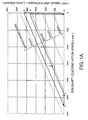
- FIG 1 shows a speed map for drive units of the propulsion system of the invention which are coupled to an epicyclic gear train.
- the left hand plane of operation (when the sun shaft of an epicyclic gear train is rotating in the negative direction according to the chosen sign convention) shown in FIG 1A, relates to a first form of the invention.
- the right hand plane of operation (when the sun shaft of an epicyclic gear train is rotating in the positive direction according to the chosen sign convention) shown in FIG 1B, relates to a second form of the invention.
- This speed map will be described in more detail below in relation to particular embodiments of each form of the invention.
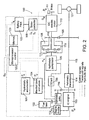
- a first embodiment which is an example of a hybrid propulsion system configured for non-transit omnibus operations in accordance with a first form of the invention, is represented by the block diagram shown in FIG 2.
- the propulsion system 100 is particularly suited to relatively low range operations, due to the need to stop frequently in the case of city operations and also to the restricted hours of operation in morning and afternoon periods, in the case of school operations.
- the propulsion system includes three disparate energy storage means, namely a fluid pressure storage means in the form of a hydrostatic accumulator 101, a chemical energy storage means in the form of a fluid fuel tank 102, and an electrical energy storage means in the form of a battery pack 103.
- the hydrostatic accumulator 101 is in a fluid hydraulic circuit with a fluid pressure control means in the form of manifold block and valves 104, a first hydraulic machine in the form of a hydrostatic pump/motor 105, a sump or oil tank 106 and a second hydraulic machine being a hydrostatic pump 107.
- the hydrostatic pump/motor 105 is coupled to a power splitting mechanical transmission means, in the form of a three shaft epicyclic gearbox 108 in the embodiment.
- the battery pack 103 is in an electrical circuit with an electrical energy conversion means in the form of a motor controller 109 which supplies drive current to an electrical machine in the form of a direct current (DC) electric motor 110.
- the drive shaft of the electric motor 110 is coupled to the epicyclic gearbox 108 and to a brake means 111.
- the fluid fuel tank 102 supplies fuel such as petrol or liquid petroleum gas (LPG), via an engine control means in the form of a throttle assembly 112, to a combustion engine in the form of a spark ignition internal combustion engine 113.
- fuel such as petrol or liquid petroleum gas (LPG)
- LPG liquid petroleum gas
- Other embodiments might employ diesel fuel where an efficient turbo supercharged compression ignition engine is specified.
- the internal combustion (IC) engine 113 is coupled, via a speed changing transmission 114 preferably an automatic transmission, to a tailshaft 115.
- a clutch and torque converter may be substituted for the automatic transmission in other embodiments.
- the hydrostatic pump 107 is coupled, preferably by a first gear set 116, between the internal combustion engine 113 and the automatic transmission 114.
- the hydrostatic pump/motor 105 is preferably coupled to a planetary gear carrier 117 of the epicyclic gearbox 108, the electric motor 110 is coupled to a sun gear 118 of the epicyclic gearbox 108, whilst the ring gear 119 is coupled to the tailshaft 115 via a second gear set 120. Accordingly, the output shaft of the epicyclic gearbox is connected in parallel to the tailshaft 115 by the second gear set 120.
- the tailshaft may, in turn, be coupled to a final drive assembly 121 of a vehicle such as an omnibus.
- hybrid propulsion system when configured in accordance with a first form of the invention, as preferably including three drive units as follows:
- the fluid drive unit and the electric drive unit are the primary drive units and are arranged to operate regeneratively.
- the combustion drive unit performs in a secondary role and does not operate regeneratively.
- a particularly preferred objective of the present invention is the minimisation of losses in the hybrid propulsion system. This may be achieved by operating the drive units, particularly the primary drive units, when most efficient over the entire speed and torque regimes. This is in part effected by the specification of the drive units, the shafts of the epicyclic gearbox to which they are connected and in part by the propulsion control means, including a microprocessor control unit or microcontroller 122 with associated memory unit 123 in the embodiment, which control means is interfaced to status transducers and control devices associated with each of the drive units.
- the propulsion control means is described in further detail hereinafter.
- the vehicle operator's demand for either positive power (drive) or negative power (braking) is represented by the transducer signal D o fed to the microcontroller 122 in FIG. 2.
- the drive units are arranged in a modular fashion so that they might be conveniently installed in and perhaps later removed from the hybrid propulsion system, whether for the purpose of maintenance, reconfiguration or upgrade.
- Each module is sized to produce the appropriate power and energy levels with a minimum energy loss over a typical operating drive cycle which are determined from a number of parameters, including:
- the microcontroller 122 receives a signal indicative of the pressure P A in the hydrostatic accumulator 101 and provides control signals, such as swash plate angle A S and valve settings P v to the manifold block of the hydrostatic pump/motor 105 and valves 104 in the hydraulic circuit.
- a typical circuit arrangement for the fluid drive unit is shown in FIG. 3.
- the hydrostatic pump/motor 105 is a 180 cc variable displacement machine, which displacement may be varied by means of a swash plate.
- a suitable hydraulic machine is, for example, a 180 cc A4VSO as manufactured by Rexroth which is rated at 190 kW with a maximum torque of 1000 Nm.
- the A4VSO machine is capable of operating in open circuit, not needing a priming pressure in order to draw fluid from a first oil sump 106b.
- the hydraulic machine supplies torque to the planetary gear carrier 117 of the epicyclic gearbox 108 (see FIG. 2).
- the omnibus has its wheel brakes applied to allow a reaction torque on the ring gear 119 of the epicyclic gearbox 108.
- the planetary carrier 117 may then be driven by the torque supplied by the electric motor 110 via the sun gear 118.
- the accumulator 101 may also be charged very efficiently by a small, auxiliary fixed displacement hydrostatic pump 107a, for example a 16 cc A2FO also manufactured by Rexroth, driven by the IC engine 113.
- the small hydrostatic pump 107a draws fluid from a second sump 106a, and may be short circuited by solenoid valve 104b when not required.
- a very small gear pump 107b is coupled to the IC engine to generate the low flow necessary for the control of swash plate angle.
- the pressure drop across the gear pump 107b is regulated around 20 bar by a low pressure regulator valve 124a.
- the gear pump may be replaced by a small auxiliary accumulator fed from the main accumulator via a pressure controlled solenoid valve, which maintains control pressure at between 20 and 30 bar.
- the pump/motor 105 is in fluid communication, via solenoid valve 104a, with the hydrostatic accumulator 101 which comprises two cylinders operating at a pressure ratio of 2:1 in the embodiment.
- this pressure ratio does not provide as much energy as a larger ratio (such as 3.45:1) on a discharge which immediately follows a complete charge, it produces higher average torque levels at the motor. It also results in a lower percentage loss of pressure following a charge, due to the smaller temperature rise of the nitrogen during compression.
- the pressure drop across the hydrostatic pump/motor 105 is limited to 345 bar by high pressure regulating valve 124b.
- There is also a non-return valve 125 on the downstream side of the accumulator 101 which prevents discharge of the high pressure portion of the hydraulic circuit if the bypass valve 104b is open.
- the primary accumulator 101a is, for example, of the oil-nitrogen type with a 50 L capacity, whilst a secondary 20 L accumulator stage 101b (approximately half the size of the primary) is used without oil and connected on the gas side of the primary accumulator 101a.
- This staged configuration has several benefits. First it is more economical as the secondary receiver does not require a bladder to separate the oil from the nitrogen and secondly the smaller secondary receiver can contain a heat transfer medium, such as some stainless steel wool or perforated sheet, to effectively add additional heat capacity to the gas resulting in thermal energy being transferred at a higher rate, thereby reducing the temperature rise on compression and also reducing the temperature drop on expansion.
- the pressure loss normally experienced is reduced when the bus is stationary because the thermal energy is stored in the heat transfer medium instead of being lost to the environment. This energy is recovered on the expansion of the gas which is not possible without the heat storage medium. Further, the pump 107a can use fuel (and thus energy) normally wasted in idling the IC engine 113 to provide some or all of the oil to maintain pressure in the accumulator.
- a tertiary "nitrogen only" accumulator stage containing a heat transfer medium may be connected after the secondary accumulator 101b. This enables the gas flowing past the medium in the secondary accumulator (i.e. to and from the tertiary accumulator) to have a higher heat transfer capability thus further reducing energy loss.
- FIG. 4 shows the elements of a conventional electric drive unit suitable for use with a hybrid propulsion system of the first form of the invention such as illustrated in FIG. 2.
- the DC motor 110 includes an armature 110a and a field winding 110f, which are supplied by an armature controller 109a and a field controller 109f, respectively.
- Power diodes 126 and 127 are provided in the armature circuit and a further power diode 128 is part of the field circuit.
- the controllers may include solid state devices, such as silicon controlled rectifiers (SCR) and the like, which may be conveniently interfaced with the microcontroller 122.
- the microcontroller monitors the status of the electric drive unit via transducers for motor speed S M and for battery current I B .
- the mechanical brake 111 on the motor shaft extension is also actuated by a control signal P B .
- a suitable rotary electric machine is a N180L manufactured by Nelco, rated for 40 kW at 3500 rpm.
- the microcontroller 122 controls the armature current I A and field current IF to efficiently produce the required torque at the shaft of the sun gear 118 over a wide range of motor speeds S M .
- Control circuits for battery 103 powered traction motors 110 of this kind may be designed by persons with normal skill in the art, and are thus not discussed in any detail.
- the electric motor 110 is not used for accelerating the omnibus below about 50 km/h.
- the motor can be sized for a smaller multiple of the level road cruise power required for the vehicle, for example a factor of two (2) rather than a factor of five (5) as in the case of a conventional (non-hybrid) electric powered omnibus.
- a factor of three (3) times level road cruise power may be required.
- a typical DC system would use a battery pack with a voltage of between 144 and 168 volts and have a mass of around 16-20% of the GVM of the bus.
- the battery pack preferably includes low maintenance valve regulated lead acid batteries, of either the gel electrolyte or absorbed glass mat types, operated at a partial state of charge (SOC).
- SOC partial state of charge
- a motor current of 250 amperes provides the rated power, although short transients of up to 500 amperes may be possible.
- Other embodiments may employ electrostatic, rather than electrochemical, electrical energy storage means such as one or more super capacitors.
- Regeneration into the battery is generally undertaken for omnibus speeds in excess of 45 km/h during braking, whether the vehicle is coming to a complete stop or running downhill at a substantially constant speed.
- the motor controller 109 limits both voltage and the maximum armature current I A as well as modulating the battery current I B via the field current to achieve the desired level of high speed regeneration into the battery 103.
- a relatively simple motor controller 109 and a medium battery voltage of 140 to 160 volts can be employed for this purpose.
- the operating voltage is approximately half that required for a typical 3-phase inverter AC type drive unit and leads to greater flexibility in the choice of batteries.
- a DC drive unit is thus preferred because it is less expensive and incurs fewer energy losses when operated as set out above, although the system can use an AC drive instead of the DC controller 109 and motor 110.
- the embodiment employs a 2 L spark ignition engine, for example a horizontally opposed 4 cylinder engine delivering approximately 90 kW as manufactured by Fuji Heavy Industries (Subaru).
- Fluid fuel such as petrol and/or LPG is stored in tank(s) 102 and delivered to the engine by the throttle assembly 112 under control of the microcontroller 122, which adjusts the throttle opening O T .
- the microcontroller also monitors the manifold pressure P M of the engine, as this parameter is indicative of engine torque.
- These engines also may include a local processor for optimising operation over a range of power demand, ambient and load conditions, with reference to a multidimensional "map" of known engine performance capabilities.
- the engine may be fuel injected and/or include mechanical or turbo supercharging.
- a clutch and torque converter may be substituted for the automatic transmission 114 of the first embodiment, whilst a mechanical brake (similar to brake 111 on the electric motor) may be coupled to the hydrostatic pump/motor 105 to reduce the leakage loss at zero pump speed.
- the speed map of FIG 1A shows the relationships of the speed of the three shafts of the epicyclic gearbox 108 and consequently the speeds of the vehicle, hydrostatic pump/motor and the electric motor.
- the tailshaft 115 is driven from the ring gear 119 via a gear reduction 120 of 1.3:1 in this illustration.
- the electric machine 110 (maximum speed of 6000 rpm) is directly connected to the sun gear 118 and the hydrostatic pump/motor 105 (maximum speed of 2,200 rpm) to the carrier 117 of the epicyclic gear set.
- the torque relationship between the three shafts of the epicyclic gearbox 108 which has a speed ratio of the sun 118 to the ring 119 of -1.92 when the speed of the carrier 117 is zero.
- a tailshaft torque of 920 Nm is required. This reflects to a maximum hydrostatic pump/motor torque of 1179 Nm. If power was to be utilised from both the electric machine and the hydrostatic machine (at full displacement) an electric torque at the sun shaft of 458 Nm would be required and half of this value (229 Nm) when the accumulator was drained of energy. This situation arises if a pressure ratio between maximum and minimum pressures of 2.0 is used.
- the optimum rated power of the electric motor is about 40 kW and a stall torque of 220 Nm is appropriate with a comer speed of about 3,500 rpm.
- the mechanical brake 111 which has a torque rating of at least 500 Nm, is attached to a through shaft of the electric machine 110 allowing utilisation of the torque of the hydrostatic machine at zero speed.
- the brake 111 on the electric machine 110 is on and the vehicle is stationary.
- the vehicle mechanical brakes (not shown) are then released and the accumulator solenoid valve 104a is opened. If the accumulator pressure P A has been maintained via the hydrostatic pump 107, the solenoid will be open and the brake 111 on the electric machine applied subsequent to the release of the vehicle brakes.
- the omnibus is accelerated by the hydrostatic machine 105, acting as a motor, until the accumulator 101 is almost empty (see path A-B in FIG. 1A).
- the pressure P A is monitored by the microcontroller 122 with status signals supplied by a pressure transducer (not shown).
- a pressure transducer not shown.
- First the field current I F is applied to the machine and secondly the armature current I A .
- the brake 111 on the electric machine 110 is released which reduces the speed of the hydrostatic motor and accelerates the electrical motor whilst continuing to apply torque to the tailshaft 115 due to the small but important inertial reaction of the elements connected to the carrier shaft 117. There is thus a substantial increase in the speed of the electric motor leading to the most efficient regime of operations (path B-C in FIG. 1A).
- the IC engine is normally not used for accelerating bus, and may be engaged above around 45 km/hr if required. For high accelerations or starting on steep hills, the IC engine can be utilized at all speeds if the automatic transmission is fitted. For an embodiment which includes a clutch under the above conditions, the IC engine drives the pump 107 to transfer power to hydrostatic motor 105.
- the vehicle operates at cruising speed as a normal electric omnibus and this is entirely satisfactory on flat terrain as a continuous power of 40 kW can be applied to the tailshaft 115, with higher power levels available on motor overload to cater for any small hills.
- the electric motor 110 is predominantly used for cruise whilst the battery pack 103 has a medium to high state of charge.
- the IC engine 113 may be utilised in preference to the battery for both cruise and hill climbing, depending on the expected distance to complete the mission for the day or before arriving at the next battery charging station.
- the battery pack 103 and hydrostatic accumulator 101 in the first form of the invention are preferably optimised for flat terrain operation to provide cruise energy (ie. driving at approximately 45 to 80 km/h) and acceleration energy, respectively. If operating in hilly terrain, the battery pack 103 could alternatively be optimised for both hill climb and cruise energy. In both cases the IC engine acts as a backup, with a significant proportion of the total energy required for a drive cycle preferably being sourced from the electricity grid between or during drive cycles.
- the battery pack could accept 10 minute charges of moderate power, 3.3 kWh from a charger with a 20 kW capacity, which is equivalent to a range of 3 to 4 km for a large 10-12 metre (12 to 15 tonne) omnibus or 6 to 8 km for a 6-7 metre (6 to 7 tonne) omnibus.
- the power absorbed by the battery charge function of the electric drive unit can provide the torque equivalent of a 0.5 ms 2 retardation.
- the electric machine 110 operates as a generator to supplement the charge state of the battery pack 103.
- the microcontroller 122 sets both the field current I F and the angle of the swash plate A S to generate a trajectory such as path D-E (see FIG. 1A) down to an electric motor speed of 3000 rpm.
- the electrical motor can no longer produce a significant torque, whereupon the displacement of the pump 105 is increased. This reduces the electric motor speed rapidly to zero (point F in FIG. 1A).
- the hydrostatic machine 105 controls the torque to the tailshaft 115 following the application of the brake 111 on the electric motor 110. Regeneration down to zero bus speed (path F-A) is thus possible producing sufficient torque to generally require minimal application of the vehicle wheel brakes.
- a brake on the hydrostatic machine is optional as the swash plate angle of the hydrostatic pump/motor 105 can be set at a maximum value (pumping) when the motor current is positive and the accumulator valve 104a is closed. These settings effectively lock the carrier shaft 117. For electric regeneration, the swash plate angle is reversed and the accumulator valve 104a is closed to again lock the carrier shaft.
- the accumulator is charged effectively and efficiently when the vehicle is stationary by using the IC engine 113 at idle and pump 107, or by using electric motor 110 and pump/motor 105.
- the automatic transmission 114 is disengaged and the speed of the engine is adjusted to bring the pressure with the flow of oil from the hydrostatic pump 107 to 345 bar in an appropriate time.
- the engine idle power used to charge the accumulator 101 can be obtained at virtually no extra cost in fuel consumption.
- the 2 litre engine at 500 rpm could provide 3 kW at normal idle fuel consumption of 1.5 L/h when the engine is operated at high throttle (manifold pressure near atmospheric pressure) and low speed. The engine speed will be constrained by the load torque during this operation.
- An automatic transmission having a torque converter without a clutch during charging for a stationary vehicle limits the engine speed to just above idle speed but no more than 900 rpm.
- the IC engine coupled to a torque converter can increase the tailshaft torque by up to 270 Nm for low vehicle speeds.
- a torque converter could be placed between the engine and the first gear set 116 driving the pump (while still retaining a clutch between the two gear sets 116, 120) which would increase the flexibility in operation.
- this may not be worth the extra mechanical complexity as the pump 107 could be fitted to the front of the engine and the torque converter attached directly to the flywheel output of the engine with a standard bell housing surrounding the torque converter.
- the control algorithm is an embodiment of a method for controlling a hybrid propulsion system of the first form of the invention.
- the propulsion control means controls the drive units from which the power and energy is delivered to or from the tailshaft, and which path will be taken by said power or energy within the hybrid propulsion system. It will be appreciated that the algorithm is iterative and responsive to changes in power demand, propulsion system state and vehicle operating mode, as described below.
- optimum condition for charging can be used for any state of accumulator 101 charge if for some reason the IC engine is not available.
- the internal combustion engine 113 enhances many of the attributes of the hybrid propulsion system of the invention. These attributes include range extension, additional acceleration capacity (with a clutch above 20 km/h and a hydrodynamic torque converter or an automatic transmission for zero speed) and enhanced hill climbing ability.
- the use of a hydrodynamic torque converter is mainly to provide improved hill climbing capability. However superior performance could be obtained using a standard automotive automatic transmission 114 which contains the clutch (transmission in neutral), the torque converter and in addition several gears, as per the embodiment shown in FIG. 2.
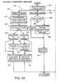
- FIG. 5A and FIG. 5B together show an overview flowchart for a typical control algorithm 200 which has a primary input, namely the input signal Do from the operator of the vehicle in the form of a demand for power, meaning power delivered to the vehicle wheels.
- the demand may be for positive power, i.e. to accelerate or to cruise, or a demand for braking of the vehicle (negative power), or a nil demand for power.
- Step 201 thus determines whether the demand is negative 202, zero 203 (vehicle stopped) or positive 204.
- the demand signal Do is derived from a transducer which is manually operated by the vehicle operator and sent to the microcontroller 122.
- the power is supplied by either the electric motor 110 or the main hydrostatic pump/motor 105.
- the choice of which unit to use is dependent on the propulsion "system state".
- the system state is determined from a number of parameters, including the energy stored in each of the accumulator 101 and the battery pack 103, the speed of the vehicle and the speed of the IC engine, the hydrostatic and electric motors and the current vehicle operating mode which are obtained in step 205. Based on this information, one or more of the drive units is selected to drive the vehicle in step 206.
- the power (or torque) generated by the electric motor or the hydrostatic motor is varied depending on the demand signal Do.
- step 211 determines that the hydrostatic motor 105 is to be used to drive the vehicle after ensuring the mechanical brake is applied to the electric motor at step 212.
- the swash plate angle A S of the hydrostatic pump/motor is varied in accordance with the available accumulator pressure P A and acceleration demand at step 213.
- the IC engine 113 is used to supplement the drive power by charging the accumulator at step 216.
- the engine's throttle opening O T is increased at step 215 only after maximum power is being extracted from the hydrostatic motor, as indicated by maximum swash angle test 214.
- the electric motor 110 is selected at step 207. If required, the accumulator solenoid valve 104a is closed and the hydrostatic pump/motor is stopped at step 208.
- the electric motor is controlled by motor controller 109 to apply power at a level dependent on the charge state of the battery pack and the acceleration demand.
- a combination of power from the batteries and the IC engine will be applied at step 210 depending on the state of charge of the battery pack 103, after checking battery state at step 209. If the battery pack is fully charged, full power is applied by the electric motor before any additional power is added by the IC engine. If the battery pack is nearly discharged, power is then added by the IC engine.
- the other drive unit coupled to the epicyclic gearbox 108 is preferably held stationary.
- the mechanical brake 111 on the motor shaft is applied to hold the motor stationary.
- a mechanical brake could also be used but an alternative is to operate the machine as a pump but with the accumulator valve 104a closed so that no oil can flow (provided the pressure generated in the hydraulic lines does not exceed their maximum capability which is preferred in this system).
- the system state is obtained at step 217 and used to determine at step 218 which of the regenerative units (i.e. the electric motor/generator or the hydrostatic pump/motor) may be used to absorb energy from the vehicle.
- the regenerative units i.e. the electric motor/generator or the hydrostatic pump/motor
- the negative power demands are preferably handled by either the electric machine (as above) or by the hydrostatic machine pumping fluid pressure into the accumulator, whilst the other machine is held stationary, see steps 220 - 221 and steps 223 - 224.
- regeneration at step 222 can be conducted at any speed within the design limitations of the hydrostatic pump/motor 105. If the accumulator 101 fills during this operation, the pump may still be used to brake the vehicle with the energy being dumped through a pressure relief valve 124b (see FIG. 3) instead of being stored in the accumulator. An alternative to dumping the energy through the relief valve is to use the vehicle's wheel brakes. In both cases, the energy is lost in heat.
- step 225 When the vehicle is stationary 203 there being no demand for wheel power, it is determined at step 225 whether the accumulator is full. If not full, it is possible to charge the accumulator at step 226 using the IC engine 113 to drive a small fixed displacement pump 107 coupled to the engine. The IC engine throttle opening O T will be varied to maintain the engine at idle speed. If a clutch is provided or neutral is selected in the automatic transmission, it is possible to charge the accumulator at a faster rate by increasing the engine speed. Generally, the main hydrostatic pump/motor 105 and the electric machine 110 would not be used, as indicated at step 227. If the accumulator is full, the IC engine idles 228 normally. In other embodiments, it may be possible to charge the battery pack from a convenient mains supply.
- the microcontroller 122 preferably facilitates adaptive operation, being arranged to record statistics of various propulsion system parameters, including armature current I A and manifold pressure P M .
- armature current I A for example the occurrences of armature current I A of the electric machine 110 in excess of the level road current requirement, allow the probability of power requirement for hill climbing and cruise to be deduced. A choice of the optimum strategy in the utilisation of any remaining battery power for either cruise or hill climb preference may then be made.
- statistics of the manifold pressure P M of the IC engine 113 will be recorded as this is directly related to engine torque and hence to engine efficiency at any speed.
- the microcontroller may adapt the control strategy to lock up the torque converter should this not have been the case previously, then disconnect the clutch and move to engine idle charge of the accumulator.
- the accumulator may be charged to a pressure which will be a function of the average speed of the bus during the preceding 10 minutes or so that the bus has been moving.
- the brake on the hydraulic machine will be released and the speed of this shaft increased with a consequential reduction in speed of the electric motor and hence demand on the battery, provided there is no increase in the torque demand.
- the energy from the accumulator with be able to reduce the energy required from the battery without necessarily reducing the bus speed.
- the omnibus is equally at home in a situation of 5 stops per kilometre or a reasonably hilly environment. It is designed with the aim of utilising less than 20% to 30% of the fluid fuel energy of a pure IC engine driven bus in stop start driving situations between 100 and 200 km ranges respectively. Hence it is preferable to limit the application to 200 km between battery charge if valve regulated lead acid batteries are installed.
- the propulsion system of the embodiments have several advantages over prior art arrangements.
- the use of the electric motor primarily for cruise mode operations allows a smaller rated machine to be employed. This leads to the possibility of using the thermal properties of the motor and battery (usually otherwise expended when accelerating from low speeds) for hill climbing. This would give a similar medium speed hill climbing capability on a current overload as would be obtained by a larger motor in prior art electric drives.
- the battery pack of the embodiment (lead acid battery pack having a mass of about 0.3 of the GVM) can store the energy of a bus descending a 2000 m hill, assuming an 80% depth of discharge at the top of the hill and fully charged at the bottom.
- the preferred method of operation for using the electric drive unit may be in a hilly environment.
- This is the antithesis of conventional operations with electric drive units as the battery is unable to cope with acceleration, level road and hill climbing demands.
- the use of relatively inexpensive electric motors and controllers in the electric drive unit offsets the cost associated with the epicyclic gearbox.
- Charging the accumulator when the vehicle is stationary substantially maintains the accelerative performance of the bus, particularly if the preferred multi-stage accumulator with low pressure ratio is employed which ameliorates the pressure drop which normally follows charging.
- This arrangement even where no IC engine is used, can achieve consistently high accelerations in relatively flat environments.
- the component sizes for the various example drive units discussed in relation to the first form of the invention are for a 6 to 7 tonne omnibus. Components for other bus sizes may be scaled linearly in accordance with anticipated GVM if the normal maximum speed is 80 km/h. However, for CBD operation 60 km/h in a more than adequate top speed capability and in cities such as Singapore, London and New York which have relatively flat topography the component sizes are adequate for a 14 tonne, 12 metre omnibus.
- the acceleration performance scales on the ratio of maximum bus kinetic energy and a bus of nearly twice the mass at 60 km/h has approximately the same energy as the smaller bus at 80 km/h.
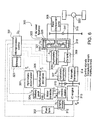
- a third embodiment of the invention relating to another form of hybrid propulsion system configured for transit omnibus operations, is represented by the block diagram shown in FIG 6.
- the propulsion system 300 is particularly suited to medium to high range operations, for example 200 to 400 km.
- the system may also be employed for suburban transit operations, perhaps as low as only 100 to 120 km.
- the propulsion system of the third embodiment again includes at least three different energy storage means.
- a hydrostatic accumulator 301 is in a fluid hydraulic circuit with a fluid pressure control means in the form of manifold block and valves 305, a series of fluid pressure energy conversion means - including a first hydrostatic pump/motor 306, a second hydrostatic pump/motor 307 and a hydrostatic pump 308 - and an oil tank 309.
- the first hydrostatic pump/motor 306 is coupled to a power splitting gearbox being a three shaft epicyclic gearbox 321
- the second hydrostatic pump/motor 307 is coupled to a first gear set 310
- the hydrostatic pump 308 is coupled to a second gear set 311 in the embodiment.
- a fluid fuel tank 302 supplies fuel such as petrol or liquid petroleum gas (LPG), via an engine control means in the form of a throttle assembly 312, to a combustion engine in the form of a spark ignition internal combustion engine 313.
- fuel such as petrol or liquid petroleum gas (LPG)
- LPG liquid petroleum gas
- IC internal combustion
- the internal combustion (IC) engine 313 is coupled by a speed changing transmission, preferably via an automatic transmission 314, to a tailshaft 315 of an omnibus.
- the second hydrostatic pump/motor 307 is coupled, by the first gear set 310, between the internal combustion engine 313 and the automatic transmission 314.
- a flywheel 303 which is depicted in FIG. 6 as being incorporated in the epicyclic gearbox 321 merely for the purposes of illustration, is coupled to the first hydrostatic pump/motor 306 via the epicyclic gearbox.
- a battery pack 304 is in electrical circuit with an electrical energy conversion means in the form of a motor controller 316 which supplies drive current to an electrical machine in the form of a direct current (DC) electric motor 317.
- the drive shaft of the electric motor 317 is coupled to the first gear set 310 on a common shaft with the second hydrostatic pump motor 307.
- the first hydrostatic pump/motor 306 is preferably coupled to a ring gear 319 of the epicyclic gearbox 321, the flywheel 303 is coupled to a sun gear 318 of the epicyclic gearbox 321, whilst the planetary gear carrier 326 is coupled to the hydrostatic pump 308 and also to the tailshaft 315 via the second gear set 311.
- the tailshaft may, in turn, be coupled to a final drive assembly 320 of a vehicle such as an omnibus.
- hybrid propulsion system when configured in accordance with another form of the invention, as preferably including four drive units as follows:
- Each of the drive units is mechanically coupled to the final drive 320 for propelling an omnibus, preferably the first hydrostatic pump/motor 306 and the flywheel 303 being selectively coupled to respective shafts of the epicyclic gearbox 321.
- a third shaft of the epicyclic gearbox is coupled to the tailshaft 315 in parallel with and the combustion drive unit.
- the fluid drive unit, the kinetic drive unit and to a lesser extent the electric drive unit are the primary drive units and are configured to perform in respective regenerative modes.
- the combustion drive unit performs in a secondary role and does not operate regeneratively.
- the particularly preferred objectives set out in relation to the embodiment shown in FIG. 2 relating to minimisation of losses and the modular arrangement of drive units also apply to the this embodiment.
- An example of the modular arrangement is that the electric drive unit of the present embodiment may be omitted in a further embodiment of the second form of the invention.
- a propulsion control means includes a microcontroller 322 and a memory 323 for storing control programs and associated data.
- the microcontroller 322 receives a signal indicative of the pressure P A in the hydrostatic accumulator 301 of the fluid drive unit and speed S m of the electric motor 317.
- the microcontroller 322 also provides control signals, such as swash plate angle A S1 , A s2 and valve settings P v to the manifold block of the hydrostatic pump/motors 306, 307 and valves 305 in the hydraulic circuit.
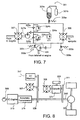
- a typical circuit arrangement for the fluid drive unit depicted in FIG. 6 is described in relation to FIG. 7.
- the first hydrostatic pump/motor 306 is a variable displacement machine, which displacement may be varied by means of a swash plate.
- a suitable hydraulic machine is a 71 cc A4VG as manufactured by Rexroth, which is rated at 125 kW with a maximum torque of 400 Nm.
- the first hydraulic machine supplies torque to the ring gear 319 of the epicyclic gearbox 321 (see FIG. 6).
- the first hydraulic machine receives torque from the gearbox, whether supplied by the final drive 320 during deceleration of the omnibus at high speeds or when the regenerative units are producing acceleration power at low speeds.
- the accumulator 301 can also be charged from the second hydraulic machine 307 when the omnibus is stationary.
- the accumulator 301 and/or the flywheel 303 may also be charged very efficiently by the second hydrostatic pump/motor 307, for example a 56 cc A4VG manufactured by Rexroth, driven by the IC engine 313 supplemented by the electric motor 317.
- a very small gear pump 307a is coupled to the IC engine to generate the low flow necessary for the control of swash plate angle.
- the pressure drop across the gear pump 307a is regulated around 20 bar by a first low pressure regulator valve 324a (see FIG. 7).
- the A4VG machines each require a priming pressure, provided by hydrostatic pump 308 (a Rexroth A2FO displacing 63 cc), in order to draw fluid from first oil sump 309b.
- a bypass valve 305c is also provided around charge pump 308.
- Each of the hydrostatic machines 306 and 307 is in fluid communication with the hydrostatic accumulator 301 which comprises two units operating at a pressure ratio of 2:1 in the embodiment.
- the fluid drive unit may operate in both closed loop and open loop configuration instead of a conventional capacity limited low pressure accumulator.
- the charge pump 308 may be driven from the tail shaft 315, or directly from the IC engine 313 in other embodiments (see FIG. 8).
- the pressure drop across the hydrostatic machines is limited to 345 bar by high pressure regulating valves 324b and 324c.
- pump 307a supplies make-up oil via non-return valves 325a and 325b. Fluid may be discharged to a second oil sump 309a via a control valve 305b.
- the primary accumulator 301a is an oil-nitrogen type with (for example) a 50 L capacity, whilst a secondary 20 L accumulator stage 301b (approximately half the size of the primary) is used without oil and connected on the gas side of the primary accumulator 301a.
- This staged accumulator configuration is similar to that described in relation to the first embodiment.
- Electrical energy from the battery pack 304 is used predominately for hill climbing and in level road operation for energy substitution.
- the electric motor 317 is used when it is most efficient as the power is preferably utilised when the torque converter in the automatic transmission 314 is locked up.
- the impedance match between the motor and the tail shaft may be provided by the gear ratios in a multi-speed automatic transmission.
- the electric motor 317 is not used for accelerating the omnibus below about 50 km/h.
- the electric drive unit may be omitted entirely. This reduces the mass of the vehicle by some 1500 kg, primarily in the battery pack 304, but increases fuel consumption without substantially altering the performance of the vehicle.
- electrical energy substitution will not be available and the vehicle will likely have a reduced hill climbing ability, this configuration may be suitable for operations over relatively flat terrain.
- the combustion drive unit includes an IC engine 313, in the embodiment a 5.0 L spark ignition engine, such as the V-configuration 8 cylinder engine with electronic fuel injection delivering approximately 165 kW and manufactured by the Ford Motor Company.
- Fluid fuel such as petrol and/or LPG is stored in tank(s) 302 and delivered to the engine by the throttle assembly 312 under control of the microcontroller 322, which adjusts the throttle opening O T .
- the microcontroller also monitors the manifold pressure P M of the engine, as this parameter is indicative of engine torque.
- the IC engine 313 is coupled to speed changing transmission in the form of a four speed automobile automatic transmission 314 with lock-up on the 3rd and 4th gears, or preferably such as a conventional 6 speed automatic transmission manufactured by Allison for use in truck and/or omnibus applications.
- the 5 litre IC engine is capable of accelerating a 12 tonne omnibus to 60 km/hr in approximately 17 seconds.
- the vehicle is thus independent of the regenerative hydrostatic-flywheel system for vehicle operations at normally accepted performance levels but with correspondingly higher fuel consumption, should the regenerative system be unavailable for any reason.
- the speed map in FIG. 1B shows the relationships of the speed of the three shafts of the epicyclic gearbox 321 and consequently the speeds of the vehicle, the first hydrostatic pump/motor and the flywheel.
- the epicyclic gearbox of the embodiment is a gear set from a 200 kW epicyclic gear reduction unit for a marine gear transmission and would be suitable for this system, but would be limited in torque to approximately 900 Nm on the ring gear, 1360 Nm on the carrier and 475 Nm on the sun shaft.
- the first hydrostatic pump/motor 306 would be coupled to the ring (input) gear 319, the planetary carrier 326 to the second gear set 311 directly coupled to the tail shaft 315 and the sun gear 318 connected to an internal 2 MJ flywheel 303 which for example is a 600 mm diameter, 280kg, 5000 rpm steel flywheel.
- the flywheel can be used to increase the inertia of the vehicle by approximately a factor of 2.3 (when the ring gear is held stationary) thus minimising the speed variation on undulating topography for speeds less than 55 km/hr. Another much smaller increase in inertia is obtained by setting the respective displacements of the hydrostatic machines so that their speeds are equal. This is equivalent to connecting the tailshaft to the ring gear shaft as well as to the carrier shaft of the epicyclic so that there is a fixed ratio between the ring and carrier shafts of the epicyclic and hence a 16% increase in the inertia of the bus.
- the flywheel rotational speed S F may be monitored by the microcontroller 322.
- the torque relationship between the three shafts of the epicyclic gearbox 321 may be determined from the speed ratio of the sun gear 318 to the carrier 326 of 0.33, which are coupled to the flywheel 303 and tailshaft 315, respectively. Similarly the speed ratio of the ring gear 319 to the carrier 317 is 0.66, which ring gear is coupled to the first hydrostatic pump motor 306.
- the speed map shows that the flywheel 303 operates always in the positive flywheel speed regime.
- the flywheel 303 is coupled to the sun shaft 318 and has a maximum speed of 5000 rpm.
- the maximum speed of the tailshaft is 3000 rpm at 103 km/h vehicle speed.
- the ring shaft is connected to the variable displacement pump/motor of the hydrostatic energy storage system, which pump/motor has a maximum speed of 4000 rpm both as a motor and as a pump in closed circuit operation.
- This mode deals with acceleration of the vehicle from a standstill or to a higher desired speed or when additional torque is required for hill climbing.
- a hybrid propulsion system configured in accordance with the invention has a high degree of flexibility, as the above description of the various operating modes demonstrates.
- the energy storage capacity of the 70 litre accumulator is 500 kJ whilst that of the flywheel is 2 MJ.
- the size of the hydrostatic machines determines the torques and hence the rates of acceleration or retardation.
- the distribution of the energy into or out of the two energy storage means is relatively independent of the torque levels. Higher torques preferably utilize the flywheel in preference to the hydrostatic accumulator for energy storage.
- flywheel energy storage when the first hydrostatic pump/motor 306 is near zero speed is very efficient, as is the use of the flywheel when the pump/motor is held stationary and the automatic is locked up in fourth gear.
- the power from the flywheel can be extracted mostly mechanically.
- the flywheel energy can be extracted when the first hydrostatic pump/motor speed is positive by transferring the engine torque to the first hydrostatic pump/motor via the hydrostatic circuit.
- all the flywheel power can be extracted at approximately 85% efficiency, but with a limit on the torque level as determined by the torque of the first hydrostatic pump/motor at maximum hydraulic pressure.
- Idle fuel consumption of the IC engine 313 is utilized successfully to recharge the accumulator and/or the flywheel for very long stops (in excess of 60 seconds).
- the IC engine is preferably utilised at near maximum torque and whilst in the fourth gear provides for the average load, the transient power being made available either hydrostatically or by the flywheel.
- continuous high power can be achieved at 60 km/hr by changing the automatic transmission 314 to third gear or by using the battery pack 304 to supply the electric motor thereby providing around 30 kW.
- the regenerative operations of the system use the hydrostatic machines and flywheel when the transfer of energy is most efficient and when the torque speed characteristics are matched.
- the fuel consumption is considerably improved, the IC engine always operating at an efficiency of greater than 22 %, the hydrostatic machine in excess of 87% and the flywheel approximately 90%.
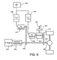
- FIG. 8 shows a fourth embodiment of a hybrid propulsion system which shows certain modifications to the system of FIG. 6 and is particularly suited to high speed cruise operations, where it is important to substantially eliminate the losses associated with the second hydrostatic pump/motor 327.
- a modified gear set 328 is moved to the other side of the automatic transmission 314 from the IC engine 313, when compared to the first gear set 310 of the embodiment shown in FIG. 6. This is facilitated by the inclusion of a further gear for coupling the second hydrostatic pump/motor 327 and electric motor 317 to the tail shaft 315.
- the modified gear set 328 provides a gear ratio of 1.25:1 between the second hydrostatic machine 327 and the tail shaft 315 and, similarly, a gear ratio of 1.25:1 between the electric motor 317 and the second hydrostatic machine 327.
- the first hydrostatic pump/motor 306 is a variable displacement machine A4VSO of 71 cc manufactured by Rexroth, whilst the second hydrostatic pump/motor 327 is also an A4VSO displacing up to 71 cc.
- Pump 308 in this embodiment is a high pressure fixed or variable displacement pump.
- FIG. 9 shows a further modified fifth embodiment, relating to the second form of the invention, wherein the fluid drive unit (as shown in FIG. 8) is replaced by a second electric motor, preferably an AC machine 335, in the electric drive unit.
- the AC machine is coupled to the epicyclic gearbox 321 and thus indirectly to the flywheel 303 and tailshaft 315. Since AC electric motor drives have the capability of maintaining the same torque when changing from positive to negative speed and vice versa (similar to a hydrostatic machine), a four quadrant DC-AC inverter 334 and AC drive motor 335 of suitable size and torque capacity, such as 400 Nm or more from 0 to 4000 rpm, is connected to a ring gear of the epicyclic gearbox 321.
- the AC portion of the electric drive (335, 334) can also act as a generator for recharging the battery pack 304 and for supplying the DC motor 317 attached to the tail shaft 315, i.e. along path S-S' in FIG. 1B, while the ring gear speed is negative.
- the AC machine 335 acts as a motor to extract energy from the flywheel.
- the reverse situation applies for regeneration, i.e. the AC machine 335 acts as a generator along path W-X and as a motor along path X-Y.
- the DC motor 317 can also act as a generator for a portion of the W-X path in FIG. 1B.
- the hybrid system of the fifth embodiment is relatively simple and has several advantages, including quiet operation, fewer components, and a smaller flywheel if a suitable high speed epicyclic gearbox is designed and manufactured. Since AC motors have a high speed capability, a higher speed rating for the ring gear could be beneficial in reducing the size of both motor and flywheel.
- the addition of a mechanical brake 333 on the flywheel 303 allows the use of the AC machine 335 for additional hill climbing or acceleration power once all of the energy has been extracted from the flywheel.
- the disadvantages include higher costs, the requirement for a higher speed epicyclic (for example 10,000 rpm ring speed) or an additional gear reduction, a charge discharge cycle on the battery pack for each acceleration and retardation, a brake on the ring shaft to reduce energy consumption during flywheel load levelling on undulating topography, a reduction in flywheel storage efficiency as the AC drive is not as efficient as the hydrostatic drive unit at near zero ring shaft speeds where the power demand for the bus is high, and although the AC drive would have lower losses when the vehicle is stationary and the flywheel is at high speed, the energy has to come from the battery.
- Other embodiments could use a DC drive in place of the AC drive on the epicyclic gearbox.
- the electric drive could be supplied from a suitable overhead catenary for at least some of its operations.
- the operation of the propulsion control means which includes microcontroller 322 and memory unit 323 will now be described in relation to the control flow charts set out in FIGS. 10, 11A, 11B and 12, relevant to the fourth embodiment.
- This embodiment is to be understood as that shown in FIG. 6 when modified by the arrangement of propulsion units shown in FIG. 8.
- the control algorithms are embodiments of a method for controlling a hybrid propulsion system of the second form of the invention.
- the propulsion control means controls the drive units from which the power and energy is delivered to or from, and which path will be taken by said power or energy within the hybrid propulsion system. It will be appreciated that the methods are iterative and are responsive to changes in power demand, propulsion system state and vehicle operating mode, as described below. In the attached flow charts, the following abbreviations are conveniently utilised for the sake of brevity:
- FIG. 10 shows an overview flowchart for a typical control algorithm which has a primary input, namely the input signal Do from the operator of the vehicle in the form of a demand for positive power, meaning power delivered to the vehicle wheels.
- the demand may be to accelerate, to cruise, or a demand for braking of the vehicle (negative power), or a nil demand.
- Step 401 thus determines whether the demand is negative 402, none 403 (vehicle stopped) or positive 404.
- the present flowchart then deals with an appropriate control algorithm for the nil power demand 403.
- the connectors shown in relation to a positive power demand (1) and negative power demand (2) are continued on FIGS. 11A and 12, respectively.
- the flywheel rotational speed S F is determined 405. If not a maximum speed, the electric motor 317 is turned off and the second hydrostatic pump/motor 327 swash angle A S2 is set to zero 406. The automatic gearbox 314 is then placed in neutral and the IC engine 313 idle power is used to increase (or maintain) the speed of the flywheel 303. This is achieved by transferring power via the hydraulic circuit consisting of the fixed displacement pump 308 connected directly to the IC engine and the variable displacement pump/motor 306 connected to the epicyclic gearbox 321 and thereby coupled to the flywheel 303.
- the accumulator pressure P A is checked 409. If the accumulator is not full, the idle power of the IC engine can be used to charge 410 the accumulator by using the hydrostatic pump 308. If the flywheel is at maximum speed and the accumulator is full, the IC engine is set to idle (no load) 411, which is a "failsafe condition". Subsequently all pump/motors are set to zero swash and the electric motor 317 is turned off 412.
- FIGS. 11A and 11B show overview flowcharts for a typical control algorithm which is an embodiment of a method for controlling the hybrid propulsion system when there is a demand for drive, whether for cruise or acceleration, ie. a positive power requirement at the vehicle wheels.
- the system state is determined from a number of parameters, including the energy stored in each of the accumulator 301, the flywheel 303 and the battery pack 304, the speed of the vehicle and the speed of the IC engine, the hydrostatic and electric motors and the current vehicle operating mode which are obtained by the microcontroller 322. Based on this information, one or more of the drive units is selected to propel the vehicle.
- the power (or torque) generated by the drive units is also varied depending on the demand signal Do derived from the vehicle operator's console.
- the first step is checking 413 the flywheel speed S F to see if there is energy in the flywheel that can be used to accelerate/drive the vehicle.
- FIG 11A deals with the algorithm used when there is flywheel energy available. If there is energy available, the speed of the first hydrostatic pump/motor 306 is checked 414 to see if it is positive or negative, refer to the speed map in FIG. 1B. During vehicle acceleration, the speed of the first pump/motor 306 will change from negative to positive as the vehicle speed increases and the flywheel speed decreases. The first hydrostatic machine 306 will operate as a pump at negative speed and a motor at positive speed without any change in swash angle A S1 . When pump/motor 306 is at zero speed, it is preferable to have maximum pressure in the accumulator 301 so that the stored energy can be used to drive the vehicle and extract further energy from the flywheel 303 as the vehicle accelerates.
- the machine If the speed (rotation) of the first hydrostatic machine 306 is negative (likely to occur with the vehicle at low speed and the flywheel at high speed), the machine operates as a pump 415 with the swash angle A S1 dependent on the acceleration demand D O .
- the oil from machine 306 can flow to either the second hydrostatic machine 327 operating as a motor and/or to the accumulator 301.
- the speed of the first machine 306 is checked 416, and if low and the energy in the accumulator is low, all of the energy will be transferred to the accumulator instead of being shared with the vehicle via the second hydrostatic pump/motor 327. This is achieved by setting the swash angle A S2 of second pump/motor 327 to zero 417, as it will not be used.
- first hydrostatic machine 306 is operating as a pump and the second hydrostatic machine 327 as a motor, with the accumulator control valve 305a open, oil will flow to the motoring machine 327 and the accumulator 301, at step 422.
- the second hydrostatic machine 327 is at low speed, most of the oil from the pumping machine 306 will flow to the accumulator 301.
- the speed of the second machine 327 increases, more oil will flow through it instead of going to the accumulator. If the maximum hydrostatic power is being transferred 423 and further acceleration is being demanded, energy can be added from the IC engine by putting the automatic into drive and increasing the IC engine throttle 424.
- first pump/motor 306 If the speed (rotation) of first pump/motor 306 is positive, it must operate as a motor to accelerate the vehicle 425. If there is energy in the accumulator 301, second pump/motor 327 will generally not be used 426 and the energy in the accumulator used 427 to drive the first motor 306, unless accumulator pressure is very high 428.
- the swash angle A S1 of first pump/motor 306 will depend on acceleration demand D O . If the maximum swash angle of first pump/motor 306 is reached 429 and further acceleration is demanded by the driver, energy can be added from either the electric motor or the IC engine. The automatic gearbox is then put into gear and the throttle on the IC engine opened so that power is now being added 419 from the IC engine. If the maximum desired engine power is reached and further power is being demanded by the driver, power can then be added 421 electrically.
- the second hydrostatic machine 327 operates 430 as a pump in a closed circuit mode with the first pump/motor.
- the automatic gearbox is put into drive and the IC engine throttle increased 431. Power from the IC engine can then go either directly to the tailshaft to drive the vehicle or to second pump/motor 327 and first pump/motor 306 to extract energy from the flywheel to accelerate or drive the vehicle. Power may also be added 432 by the electric motor 317 as required.
- FIG. 11B deals with the situation where flywheel energy is not available, continuing from FIG. 11A. If there is no energy available in the flywheel, first pump/motor 306 is set to zero swash angle and is not operated 434, subsequent to obtaining 433 the system state. The states of charge of the battery pack 304 and the accumulator 301 are considered and the choice of unit for acceleration determined 435. If there is energy in the accumulator, second hydrostatic machine 327 is operated 436 as a motor to accelerate the vehicle in preference to the use of the electric motor 317. Thus the swash angle A S2 is varied 437 depending on the acceleration demand.
- the idle power of the IC engine 313 is transferred 439 to the vehicle via hydrostatic pump 308 which adds to the oil flow helping to maintain the pressure of the accumulator 301. If the maximum swash is reached at step 438 and further acceleration is demanded, the automatic gearbox is placed into drive and the throttle of the IC engine increased 440. If the maximum desired engine power is reached 441 and further power is being demanded by the driver, power can then be added 442 by the electric drive unit if available.
- the accumulator 301 If there is no energy in the accumulator 301, energy is supplied 443 from the battery pack 304 and the IC engine 313.
- the accumulator valve 305a is closed and the second pump/motor 327 set to zero swash as it is not utilised 444.
- energy is added 446 either from the electric motor or the IC engine or both together. If the state of charge of the batteries is high, the electric motor is used first. If maximum electrical power is being applied, the IC engine is then used to supplement the power. If the state of charge of the batteries is low, the IC engine is used first with power from the batteries being added if additional power is required. The power from the batteries will be limited if their state of charge is very low.
- FIG. 12 shows an overview flowchart for a typical control algorithm which is an embodiment of a method for controlling the hybrid propulsion system when there is a demand for braking, ie. a negative power requirement at the vehicle wheels.
- energy can be stored either in the flywheel 303, the hydrostatic accumulator 301 or the battery pack 304. Initially the speed of the flywheel 303 is tested 450.
- flywheel is not at maximum speed: If the flywheel is not at maximum speed, energy can be stored in the flywheel. This is controlled by operating first hydrostatic machine 306 as a pump if its speed is positive or as a motor if its speed is negative. Accordingly the speed (rotation) of the first pump/motor 306 is checked 451 and, if positive (typically when the vehicle is at high speed and the flywheel is at a low speed), first hydrostatic machine 306 is operated 452 as a pump. The oil flow will charge the accumulator 301 and energy will also be stored in the flywheel 303. The swash angle A S1 of the machine 306 will depend on the braking demand from the driver.
- the swash angle is monitored 453 and, if not at a maximum, second hydrostatic machine 327 and the electric motor 317 need not be used 454 since the first pump/motor 306 is providing sufficient braking for the vehicle.
- the IC engine 313 will be at idle with the gearbox 314 in neutral (the idle fuel power could be used with hydrostatic pump 308 for an additional charge into the accumulator). If the swash angle of pump/motor 306 has reached a maximum and further braking is demanded, energy can be stored in either the accumulator by using the second hydrostatic machine 327 as a pump or in the batteries by using the electric machine 317 as a generator.
- the system state is assessed 455 and a regenerative mode determined 456 on this basis as set out briefly in steps 457 and 458 of FIG. 12.
- the second hydrostatic machine 327 will generally not be used and regeneration energy will go into the batteries 304.
- both second hydrostatic machine 327 and the electric machine 317 could be used. If the vehicle speed is low, or the electric machine speed were not high enough to store energy in the batteries, the electric machine will not be used and second hydrostatic machine 327 operated as a pump to store energy in the accumulator 301.
- first hydrostatic machine 306 must operate 459 as a motor.
- the electric machine 317 will not be used 460 for regeneration as its speed will generally be too low to generate sufficient voltage to charge the battery pack.
- Braking is regulated 463 by varying the swash angles of first pump/motor 306 and second pump/motor 327 (first hydrostatic machine operating as a motor and second hydrostatic machine operating as a pump). This can be carried out in either closed circuit mode (without the accumulator) or open circuit mode (with the accumulator).
- the IC engine 313 can add power 462 to the accumulator via hydrostatic pump 308. If operating without the accumulator the IC engine will generally be set to idle.
- flywheel at maximum speed If the flywheel is at maximum speed, the swash angle of the first hydrostatic machine 306 is set 464 to zero and no energy is transferred to the flywheel 303. Regeneration can only occur into the batteries or the accumulator, although it is unlikely that regeneration into the batteries will be possible as the vehicle speed (hence electric motor speed) will be low as the flywheel should normally be at maximum speed when the vehicle is near zero speed, except in the case of a long downhill run.
- Braking energy can be stored in either the accumulator 301 by using second hydrostatic machine 327 as a pump or into the batteries by using the electric motor/generator as a generator. Again the system state is assessed 465 and a regenerative mode determined 466 on this basis. If the vehicle speed is high (unlikely if the flywheel is at maximum speed), second hydrostatic machine 327 will generally not be used and regeneration energy will be transferred into the batteries. If the vehicle speed is low, or the electric motor speed would not be high enough to store energy in the batteries, the electric motor (unless an AC machine) will not be used and second hydrostatic machine 327 operated as a pump to store energy in the accumulator.
- the propulsion system of the embodiments of the second form of the invention have several advantages over prior art arrangements for transit applications.
- the flywheel, accumulator, ICE and battery can all be used and brought into operation sequentially as power demand increases or as the available energy in the flywheel and the accumulator decrease. This situation arises especially when the speed exceeds 40 km/hr where high power is required.
- Accumulator energy if available, can be used at any bus speed to reduce the energy demands on the ICE or the battery.
- the electric motor and battery pack enable electric power to be used, preferably when the motor speed corresponds to the medium to high vehicle speed range.
- the propulsion control system is preferably arranged to ensure that normally battery power would only be used when the torque converter was locked. Regeneration can be accomplished at all speeds in excess of 50 km/hr at 30-40 kW power levels. It can also be used in flywheel regeneration mode if the speed of the first hydrostatic machine is positive and the accumulator is full.
- the component sizes mentioned in the specification in relation to the various drive units for the second form of the invention are for a 10 to 12 tonne omnibus. Components for other bus sizes may be scaled linearly in accordance with anticipated GVM if the normal maximum speed is 100 km/h.
- the acceleration performance scales on the ratio of maximum bus kinetic energy and a bus of nearly twice the mass at 75 km/h has approximately the same energy as the smaller bus at 100 km/h.
- the propulsion system of the invention is believed to be the first to be proposed with up to 4 different energy sources available for vehicle propulsion.
- the propulsion system will perform in all possible transit omnibus operating conditions in any major urban area.
- the versatility of the system is such that when operating in less demanding environments some components of the system need not be installed. These environments include lower maximum speeds, lower acceleration demands, level roads, or where adequate high rate battery charging stations are available. This versatility reduces the capital cost of the vehicle whilst meeting operational requirements with minimum energy consumption. It also enables the use of the preferred and most efficient source of energy and a balance between electricity from the grid or fluid (liquid or gaseous) fuel for the IC engine.
Landscapes
- Engineering & Computer Science (AREA)
- Mechanical Engineering (AREA)
- Chemical & Material Sciences (AREA)
- Combustion & Propulsion (AREA)
- Transportation (AREA)
- General Engineering & Computer Science (AREA)
- Automation & Control Theory (AREA)
- Electric Propulsion And Braking For Vehicles (AREA)
- Hybrid Electric Vehicles (AREA)
Abstract
Claims (23)
- Un système de propulsion hybride (100) destiné à l'exploitation de véhicules, ledit système de propulsion comprenant :caractérisé en ce que :(a) une transmission mécanique à répartition de puissance (108) destinée à être couplée à un vilebrequin (115) du véhicule ;(b) un premier organe d'entraínement (110) aménagé en vue d'un fonctionnement régénératif et couplé à la transmission mécanique à répartition de puissance (108) ;(c) un deuxième organe d'entraínement (105) aménagé en vue d'un fonctionnement régénératif et couplé, indépendamment dudit premier organe d'entraínement (110), à la transmission mécanique à répartition de puissance (108) ;(d) un troisième organe d'entraínement non régénératif (113) destiné à être couplé au vilebrequin (115) ; et(e) un moyen de commande de la propulsion (122) destiné à coordonner le fonctionnement des organes d'entraínement (105, 110, 113) conformément à une pluralité de modes prédéterminés correspondant à un cycle d'entraínement dudit véhicule ;ledit troisième organe d'entraínement non régénératif (113) est couplé en permanence au vilebrequin (115) en parallèle à ladite transmission mécanique à répartition de puissance (108) ; etchacun des premier, deuxième et troisième organes d'entraínement (110, 105, 113) comporte un type différent de moyen d'accumulation de l'énergie (102, 101, 103).
- Un système de propulsion hybride selon la revendication 1, dans lequel la transmission mécanique à répartition de puissance (108) comporte un engrenage épicycloïdal (108) ayant une couronne (119) sur un premier arbre, une roue solaire (118) sur un deuxième arbre et un ensemble porteur de roue planétaire (117) sur un troisième arbre.
- Un système de propulsion hybride selon soit la revendication 1 soit la revendication 2, dans lequel le moyen de commande de la propulsion (122) comporte un microcontrôleur (122) connecté à une série de transducteurs d'état et à une série de moyens de commande,
lesquels transducteurs d'état et moyens de commande sont associés à des éléments respectifs du système de propulsion (100). - Un système de propulsion hybride selon la revendication 3, dans lequel le microcontrôleur (122) comporte des moyens de mémorisation (123) pour y stocker les signaux reçus des transducteurs d'état associés à chaque organe d'entraínement,
lesquels signaux d'état indiquent l'état de fonctionnement des organes d'entraínement respectifs,
lesquels moyens de mémorisation (123) stockent également des données qui indiquent les signaux de commande correspondants appliqués aux moyens de commande des organes d'entraínement ;
au moyen duquel les données de signal d'état mémorisées et les données de signal de commande mémorisées sont utilisées en vue de la commande soit déterministe soit adaptative du système de propulsion hybride (100). - Un système de propulsion hybride selon la revendication 1, dans lequel la transmission mécanique à répartition de puissance (108) comporte un engrenage épicycloïdal (108), ledit système de propulsion comportant en outre :au moyen duquel l'engrenage épicycloïdal (108) fournit un couple au vilebrequin (115) en vue de propulser le véhicule ou de recevoir un couple du vilebrequin (115) en vue de ralentir le véhicule.(A) une couronne (119) de l'engrenage épicycloïdal (108) aménagée pour le couplage au vilebrequin (115) ;(B) le premier organe d'entraínement (110) couplé à une roue solaire (118) de l'engrenage épicycloïdal (108) ;(C) le deuxième organe d'entraínement (105) couplé à un ensemble porteur de roue planétaire (117) de l'engrenage épicycloïdal (108) ; et(D) le troisième organe d'entraínement (113) couplé au vilebrequin (115) par l'intermédiaire d'une transmission à variation de vitesse (114) ;
- Un système de propulsion hybride selon la revendication 5, dans lequel :le premier organe d'entraínement (110) comporte un moyen d'accumulation de l'énergie électrique (103) et un moyen associé de conversion de l'énergie électrique;le deuxième organe d'entraínement (105) comporte un moyen de stockage de la pression hydraulique (101) et un moyen associé de conversion de l'énergie de la pression hydraulique; etle troisième organe d'entraínement (113) comporte un moyen de stockage de l'énergie chimique (102) et un moteur à combustion associé.
- Un système de propulsion hybride selon la revendication 6, dans lequel les modes prédéterminés coordonnés par le moyen de commande de la propulsion (122) comprennent :(i) un mode d'accélération, dans lequel le moyen de conversion de la pression hydraulique (105) ou le moyen de conversion de l'énergie électrique fournit de l'énergie au vilebrequin (115), complétée par l'énergie provenant du moteur à combustion (113) selon les besoins ;(ii) un mode de croisière, dans lequel le moyen de conversion de l'énergie électrique fournit de l'énergie au vilebrequin (115), complétée par l'énergie provenant du moteur à combustion (113) selon les besoins ;(iii) un mode de décélération, dans lequel le moyen de conversion de l'énergie de la pression hydraulique (105) et le moyen de conversion de l'énergie électrique fonctionnent chacun de manière régénérative afin de récupérer de l'énergie du vilebrequin (115) et de fournir de l'énergie, respectivement, au moyen de stockage de la pression hydraulique (101) et au moyen de stockage de l'énergie électrique (103) ; et(iv) un mode stationnaire, dans lequel un organe d'entraínement sélectionné fournit de l'énergie pour réapprovisionner le moyen de stockage de la pression hydraulique (101) selon les besoins.
- Un système de propulsion hybride selon la revendication 1, dans lequel la transmission mécanique à répartition de puissance comporte un engrenage épicycloïdal (321), ledit système de propulsion comportant en outre :au moyen duquel l'engrenage épicycloïdal (321) fournit un couple au vilebrequin (315) en vue de propulser le véhicule ou reçoit un couple du vilebrequin (315) en vue de ralentir le véhicule.(A) un ensemble porteur de roue planétaire (326) de l'engrenage épicycloïdal (321) aménagé pour le couplage au vilebrequin (315) ;(B) le premier organe d'entraínement couplé à une couronne (319) de l'engrenage épicycloïdal (321) ;(C) le deuxième organe d'entraínement couplé à une roue solaire (318) de l'engrenage épicycloïdal (321) ; et(D) le troisième organe d'entraínement couplé au vilebrequin (315) par l'intermédiaire d'une transmission à variation de vitesse (314) ;
- Un système de propulsion hybride selon la revendication 8, dans lequel :le premier organe d'entraínement comporte un moyen de stockage de la pression hydraulique (301) et un moyen associé de conversion de l'énergie de la pression hydraulique (306) ;le deuxième organe d'entraínement comporte un moyen de stockage de l'énergie mécanique (303) ; etle troisième organe d'entraínement comporte un moyen de stockage de l'énergie chimique (302) et un moteur à combustion associé (313).
- Un système de propulsion hybride selon la revendication 9, comportant en outre un quatrième organe d'entraínement aménagé en vue d'un fonctionnement régénératif et couplé à l'ensemble porteur de roue planétaire (326),
lequel quatrième organe d'entraínement comporte un deuxième moyen de stockage de la pression hydraulique (307) associé au moyen de stockage de la pression hydraulique (301). - Un système de propulsion hybride selon la revendication 9 dans lequel les modes prédéterminés coordonnés par le moyen de commande de la propulsion comprennent :(i) un mode d'accélération, dans lequel le moyen de stockage de l'énergie mécanique (303) fournit de l'énergie au vilebrequin (315), commandé par l'énergie fournie par ou provenant du moyen de conversion de l'énergie de la pression hydraulique (306) et complétée par l'énergie provenant du moteur à combustion (313) selon les besoins;(ii) un mode de croisière, dans lequel le moteur à combustion (313) fournit de l'énergie au vilebrequin (315), complétée par l'énergie provenant du moyen de stockage de l'énergie mécanique (303) commandé par le moyen de conversion de l'énergie de la pression hydraulique (306) selon les besoins ;(iii) un mode de décélération, dans lequel le moyen de conversion de l'énergie de la pression hydraulique (306) fonctionne de manière à régulariser la régénération d'énergie provenant du vilebrequin (315) afin d'alimenter soit le moyen de stockage de l'énergie mécanique (303) soit le moyen de stockage de la pression hydraulique (301) ; et(iv) un mode stationnaire, dans lequel un organe d'entraínement sélectionné fournit de l'énergie pour réapprovisionner le moyen de stockage de l'énergie mécanique (303) ou le moyen de stockage de la pression hydraulique (301) selon les besoins.
- Un système de propulsion hybride selon la revendication 8, dans lequel :le premier organe d'entraínement comporte un moyen d'accumulation de l'énergie électrique (304) et un moyen associé de conversion de l'énergie électrique (335) ;le deuxième organe d'entraínement comporte un moyen de stockage de l'énergie mécanique (303) ; etle troisième organe d'entraínement comporte un moyen de stockage de l'énergie chimique (302) et un moteur à combustion associé (313).
- Un système de propulsion hybride selon la revendication 12 comportant en outre un quatrième organe d'entraínement couplé à l'ensemble porteur de roue planétaire (326), lequel quatrième organe d'entraínement comporte un deuxième moyen de conversion de l'énergie électrique (317) associé au moyen de stockage de l'énergie électrique (304).
- Un système de propulsion hybride selon la revendication 12, dans lequel les modes prédéterminés coordonnés par le moyen de commande de la propulsion comprennent :(i) un mode d'accélération, dans lequel le moyen de stockage de l'énergie mécanique (303) fournit de l'énergie au vilebrequin (315), commandé par l'énergie fournie par ou provenant du moyen de conversion de l'énergie mécanique (335) et complétée par l'énergie provenant du moteur à combustion (313) selon les besoins ;(ii) un mode de croisière, dans lequel le moteur à combustion (313) fournit de l'énergie au vilebrequin (315), complétée par l'énergie provenant du moyen de stockage de l'énergie mécanique (303) commandé par le moyen de conversion de l'énergie électrique (335) selon les besoins ;(iii) un mode de décélération, dans lequel le moyen de conversion de l'énergie électrique (335) fonctionne de manière à régulariser la régénération d'énergie provenant du vilebrequin (315) afin d'alimenter soit le moyen de stockage de l'énergie mécanique (303) soit le moyen de stockage de l'énergie électrique (304) ; et(iv) un mode stationnaire, dans lequel un organe d'entraínement sélectionné fournit de l'énergie pour réapprovisionner le moyen de stockage de l'énergie mécanique (303) ou le moyen de stockage de l'énergie électrique (304) selon les besoins.
- Un système de propulsion hybride selon l'une quelconque des revendications 6, 7, 9 ou 10, dans lequel le moyen de stockage de la pression hydraulique (101, 301) comporte au moins un accumulateur hydrostatique (101, 301) et le moyen de conversion de l'énergie de la pression hydraulique (105, 306, 307, 308) comporte au moins une pompe/un moteur hydrostatique (105, 306) et un appareil hydrostatique auxiliaire (107, 307) couplé au moteur à combustion (113, 313).
- Un système de propulsion hybride selon l'une quelconque des revendications 6, 7, 12, 13 ou 14, dans lequel le moyen de stockage de l'énergie électrique (103, 304) comporte une batterie (103, 304) et/ou au moins un supercondensateur, et le moyen de conversion de l'énergie électrique comporte un appareil électrique rotatif et un appareil électrique rotatif auxiliaire couplé au moteur à combustion (113, 313).
- Un système de propulsion hybride selon la revendication 16, dans lequel le moyen de conversion de l'énergie électrique comporte en outre un convertisseur d'énergie à semiconducteurs.
- Un système de propulsion hybride selon l'une quelconque des revendications 11 à 14, dans lequel le moyen de stockage de l'énergie mécanique (303) comporte un moyen de stockage de l'énergie cinétique comportant au moins un volant (303).
- Un système de propulsion hybride selon l'une quelconque des revendications 6, 7, 9, 12 ou 13, dans lequel le moyen de stockage de l'énergie chimique (102, 302) comporte un ou plusieurs réservoirs de combustible fluide (102, 302) destinés au stockage de combustible liquide ou gazeux, et le moteur à combustion (313) est un moteur à compression interne à allumage par étincelle ou par compression.
- Un système de propulsion hybride selon l'une quelconque des revendications 5 à 19, dans lequel au moins un arbre de l'engrenage épicycloïde (108, 321) est couplé à un moyen de freinage (111).
- Un système de propulsion hybride selon l'une quelconque des revendications 5 à 20, dans lequel la transmission à variation de vitesse (114, 314) comporte un embrayage et un convertisseur de couple.
- Un système de propulsion hybride selon l'une quelconque des revendications 5 à 20, dans lequel la transmission à variation de vitesse (114, 314) comprend une transmission automatique (114, 314), y compris un convertisseur de couple à verrouillage.
- Une méthode de commande du système de propulsion hybride (300) pour un véhicule, lequel système de propulsion comporte au moins deux organes d'entraínement (303, 306) aménagés en vue d'un fonctionnement régénératif et couplés à une transmission mécanique à répartition de puissance (321), indépendamment l'un de l'autre, laquelle transmission mécanique (321) est couplée avec un troisième organe d'entraínement non régénératif (313) au vilebrequin (315) du véhicule ;
caractérisé en ce que:la méthode étant caractérisées en ce que :ledit troisième organe d'entraínement non régénératif (313) est couplé en permanence au vilebrequin (315) en parallèle à ladite transmission mécanique à répartition de puissance (321) ; etchacun desdits au moins deux organes d'entraínement (303, 306) et dudit troisième organe d'entraínement (313) comporte un type différent de moyen de stockage de l'énergie (301, 302, 303), ladite méthode comprenant les étapes suivantes:la détermination de l'état courant du système de propulsion (300) par le contrôle de l'état de chaque organe d'entraínement, y compris les vitesses de régime et les niveaux de stockage d'énergie respectifs ;la réception d'un signal de demande (DO) indiquant le mouvement véhiculaire désiré ; etsi le signal de demande (DO) indique qu'une puissance négative des roues destinée àfreiner le véhicule est désirée :la mise en marche de l'un quelconque des organes d'entraínement régénératifs (303, 306) en vue de la régénération conformément à l'état courant du système; ousi le signal de demande (DO) indique qu'une puissance positive des roues est désirée en vue de la croisière ou de l'accélération du véhicule:la mise en marche de l'un quelconque des organes d'entraínement (303, 306) en vue de la propulsion conformément à l'état courant du système ; ousi le signal de demande indique qu'aucune puissance des roues n'est désirée, le véhicule étant stationnaire :la mise en marche des organes d'entraínement sélectionnés (303, 306) en vue de réapprovisionner les moyens de stockage de l'énergie (301, 303) associés aux organes d'entraínement régénératifs (303, 306) ;lesdites étapes sont répétées afin de régulariser le système de propulsion (300) de façon à optimiser le fonctionnement desdits au moins deux organes d'entraínement (303, 306) et dudit troisième organe d'entraínement (313) afin d'obtenir l'état du système désiré, tel qu'indiqué par le signal de demande (DO).
Applications Claiming Priority (5)
| Application Number | Priority Date | Filing Date | Title |
|---|---|---|---|
| AUPO631797 | 1997-04-18 | ||
| AUPO6317A AUPO631797A0 (en) | 1997-04-18 | 1997-04-18 | Hybrid propulsion system for non-transit vehicles |
| AUPO645797 | 1997-04-29 | ||
| AUPO6457A AUPO645797A0 (en) | 1997-04-29 | 1997-04-29 | Hybrid propulsion system for transit vehicles |
| PCT/AU1998/000275 WO1998047732A1 (fr) | 1997-04-18 | 1998-04-17 | Systeme de propulsion hybride pour vehicules routiers |
Publications (3)
| Publication Number | Publication Date |
|---|---|
| EP0975480A1 EP0975480A1 (fr) | 2000-02-02 |
| EP0975480A4 EP0975480A4 (fr) | 2001-07-25 |
| EP0975480B1 true EP0975480B1 (fr) | 2004-02-18 |
Family
ID=25645402
Family Applications (1)
| Application Number | Title | Priority Date | Filing Date |
|---|---|---|---|
| EP98916631A Expired - Lifetime EP0975480B1 (fr) | 1997-04-18 | 1998-04-17 | Systeme de propulsion hybride pour vehicules routiers |
Country Status (6)
| Country | Link |
|---|---|
| US (1) | US6170587B1 (fr) |
| EP (1) | EP0975480B1 (fr) |
| CA (1) | CA2286615C (fr) |
| DE (1) | DE69821750T2 (fr) |
| NZ (1) | NZ500627A (fr) |
| WO (1) | WO1998047732A1 (fr) |
Cited By (1)
| Publication number | Priority date | Publication date | Assignee | Title |
|---|---|---|---|---|
| US9435355B2 (en) | 2012-06-29 | 2016-09-06 | Eaton Corporation | Hydraulic launch assist system |
Families Citing this family (192)
| Publication number | Priority date | Publication date | Assignee | Title |
|---|---|---|---|---|
| US20040173396A1 (en) * | 1998-09-03 | 2004-09-09 | Permo-Drive Research And Development Pty. Ltd. | Energy management system |
| AUPP565098A0 (en) * | 1998-09-03 | 1998-09-24 | Hbp Permo-Drive Pty Ltd | Energy management system |
| US6554088B2 (en) | 1998-09-14 | 2003-04-29 | Paice Corporation | Hybrid vehicles |
| JP3153527B2 (ja) * | 1999-04-05 | 2001-04-09 | 本田技研工業株式会社 | ハイブリッド自動車の制御装置 |
| US7729831B2 (en) | 1999-07-30 | 2010-06-01 | Oshkosh Corporation | Concrete placement vehicle control system and method |
| US7107129B2 (en) * | 2002-02-28 | 2006-09-12 | Oshkosh Truck Corporation | Turret positioning system and method for a fire fighting vehicle |
| DE10036504B4 (de) * | 1999-08-02 | 2011-05-19 | Schaeffler Technologies Gmbh & Co. Kg | Antriebsstrang |
| JP3654074B2 (ja) * | 1999-08-27 | 2005-06-02 | トヨタ自動車株式会社 | 複数の原動機を備えた車両の制御装置 |
| US7185722B1 (en) * | 2000-02-04 | 2007-03-06 | Hitachi, Ltd. | Power transmission apparatus of motor vehicles |
| US20020179354A1 (en) * | 2000-05-02 | 2002-12-05 | Sail D. White Enterprises, Inc. | Extended range electric vehicle |
| US6490945B2 (en) * | 2001-01-10 | 2002-12-10 | New Venture Gear, Inc. | Twin clutch automated transmission with integrated transfer case |
| US7379797B2 (en) * | 2001-01-31 | 2008-05-27 | Oshkosh Truck Corporation | System and method for braking in an electric vehicle |
| US7277782B2 (en) * | 2001-01-31 | 2007-10-02 | Oshkosh Truck Corporation | Control system and method for electric vehicle |
| US6881165B2 (en) * | 2001-02-07 | 2005-04-19 | Toyota Jidosha Kabushiki Kaisha | Hydraulic control apparatus of vehicle and control method |
| US6455947B1 (en) | 2001-02-14 | 2002-09-24 | Bae Systems Controls, Inc. | Power combining apparatus for hybrid electric vehicle |
| JP2002247701A (ja) * | 2001-02-22 | 2002-08-30 | Toyota Central Res & Dev Lab Inc | 補機駆動装置 |
| US6378638B1 (en) | 2001-03-14 | 2002-04-30 | New Venture Gear, Inc. | Drive axle for hybrid vehicle |
| US6401850B1 (en) | 2001-03-14 | 2002-06-11 | New Venture Gear, Inc. | Electric drive axle for hybrid vehicle |
| US6484834B2 (en) | 2001-03-14 | 2002-11-26 | New Venture Gear, Inc. | Electric drive motor axle with integrated reduction and differential gearset |
| US6702709B2 (en) | 2001-04-09 | 2004-03-09 | New Venture Gear, Inc. | Drivetrain for hybrid motor vehicle |
| DE10128758A1 (de) * | 2001-06-13 | 2002-12-19 | Bosch Gmbh Robert | Verfahren und Einrichtung zur Ansteuerung eines Hybridfahrzeugs |
| DE10214598B4 (de) * | 2002-04-03 | 2009-05-07 | Cnh Belgium N.V. | Fahrantrieb für eine landwirtschaftliche Erntemaschine mit Steuerung der Fahrgeschwindigkeit bei Straßenfahrten |
| US7387182B2 (en) * | 2002-04-08 | 2008-06-17 | Patrick Fleming | Turbine generator regenerative braking system |
| US6758295B2 (en) * | 2002-04-08 | 2004-07-06 | Patrick Fleming | Turbine generator regenerative braking system |
| US7392122B2 (en) | 2002-06-13 | 2008-06-24 | Oshkosh Truck Corporation | Steering control system and method |
| AUPS300902A0 (en) * | 2002-06-18 | 2002-07-11 | Permo-Drive Research And Development Pty Ltd | Decoupling mechanism for hydraulic pump/motor assembly |
| FR2842144B1 (fr) | 2002-07-11 | 2005-01-28 | Peugeot Citroen Automobiles Sa | Procede et dispositif de transmission de puissance pour une vehicule automobile comprenant un moteur thermique et au moins une machine electrique |
| US6775601B2 (en) * | 2002-08-06 | 2004-08-10 | Delphi Technologies, Inc. | Method and control system for controlling propulsion in a hybrid vehicle |
| KR100447754B1 (ko) * | 2002-08-26 | 2004-09-08 | 현대모비스 주식회사 | 전기모터에 의한 차량 구동 및 제동 시스템 |
| US20040044448A1 (en) * | 2002-08-27 | 2004-03-04 | Ford Motor Company | Vehicle systems controller with modular architecture |
| AU2002951538A0 (en) * | 2002-09-20 | 2002-10-03 | Permo-Drive Research And Development Pty Ltd | Regenerative drive system for trailers |
| FR2849142B1 (fr) * | 2002-12-20 | 2007-01-26 | Poclain Hydraulics Ind | Systeme de freinage pour un vehicule entraine par au moins un moteur hydraulique alimente en circuit ferme |
| US6971463B2 (en) * | 2002-12-23 | 2005-12-06 | Cnh America Llc | Energy recovery system for work vehicle including hydraulic drive circuit and method of recovering energy |
| US6769400B1 (en) * | 2003-01-24 | 2004-08-03 | General Motors Corporation | Method for controlling emissions |
| JP2005042684A (ja) * | 2003-07-25 | 2005-02-17 | Denso Corp | 電動機付ターボチャージャの電力制御装置および電動ターボチャージャ装置 |
| US6843750B1 (en) | 2003-07-30 | 2005-01-18 | Arvinmeritor Technology, Llc | Two-speed gearbox with integrated differential |
| US7028583B2 (en) * | 2003-07-30 | 2006-04-18 | Arvinmeritor Technology, Llc | Axle assembly with transverse mounted electric motors |
| US6978853B2 (en) * | 2003-07-30 | 2005-12-27 | Arvinmeritor Technology Llc | Axle assembly with parallel mounted electric motors |
| US7149617B2 (en) * | 2003-11-05 | 2006-12-12 | Zf Meritor, Llc | Method of timed shift to neutral in apparent stationary modes |
| US20050121532A1 (en) * | 2003-12-05 | 2005-06-09 | Reale Michael J. | System and method for district heating with intercooled gas turbine engine |
| US6979913B2 (en) * | 2004-02-20 | 2005-12-27 | Contour Hardening, Inc. | Vehicle mounted electrical generator system |
| US7146266B2 (en) * | 2004-07-01 | 2006-12-05 | Ford Global Technologies, Llc | Controlling a hydraulic hybrid vehicle powertrain having an internal combustion engine and a hydraulic pump/motor |
| US7105937B2 (en) * | 2004-07-14 | 2006-09-12 | Hamilton Sundstrand Corporation | Adjustable variable frequency starter/generator system |
| WO2006017901A1 (fr) * | 2004-08-18 | 2006-02-23 | Permo-Drive Research And Development Pty Ltd | Systeme d'un entrainement a reinjection de fluide hydraulique et son systeme de controle |
| AU2005274686B2 (en) * | 2004-08-18 | 2010-10-28 | Permo-Drive Research And Development Pty Ltd | Hydraulic regenerative drive system and control |
| US7381150B2 (en) * | 2004-08-18 | 2008-06-03 | Permo-Drive Research & Development Pty. Ltd. | Hydraulic regenerative drive system and controls |
| CA2479890A1 (fr) * | 2004-09-27 | 2006-03-27 | Samuel Beaudoin | Systeme de generatrice a haut rendement et transmission a variation continue pour ce systeme |
| US7273122B2 (en) * | 2004-09-30 | 2007-09-25 | Bosch Rexroth Corporation | Hybrid hydraulic drive system with engine integrated hydraulic machine |
| US7311163B2 (en) * | 2004-11-16 | 2007-12-25 | Eaton Corporation | Regeneration and brake management system |
| EP1824699B1 (fr) | 2004-11-22 | 2010-10-06 | Bosch Rexroth Corporation | Systeme d'entrainement hybride hydro-electrique pour automobile |
| US7689330B2 (en) * | 2004-12-01 | 2010-03-30 | Ise Corporation | Method of controlling engine stop-start operation for heavy-duty hybrid-electric and hybrid-hydraulic vehicles |
| US20100145562A1 (en) * | 2004-12-01 | 2010-06-10 | Ise Corporation | Method of Controlling Engine Stop-Start Operation for Heavy-Duty Hybrid-Electric Vehicles |
| US7689331B2 (en) * | 2004-12-01 | 2010-03-30 | Ise Corporation | Method of controlling engine stop-start operation for heavy-duty hybrid-electric and hybrid-hydraulic vehicles |
| US7395887B2 (en) * | 2004-12-23 | 2008-07-08 | Bosch Rexroth Corporation | Complementary regenerative torque system and method of controlling same |
| US7597172B1 (en) * | 2005-04-22 | 2009-10-06 | Parker-Hannifin Corporation | Gear box for hydraulic energy recovery |
| CN100448711C (zh) * | 2005-05-30 | 2009-01-07 | 比亚迪股份有限公司 | 机动车辆的变速装置及其变速方法 |
| FR2887186B1 (fr) * | 2005-06-15 | 2008-09-26 | Irisbus France Sa | Vehicule urbain et dispositif de recuperation d'energie pour ce vehicule |
| US7479091B2 (en) * | 2005-08-15 | 2009-01-20 | Tai-Her Yang | Engine running at fixed speed incorporated controllable transmission power system |
| JP2007062577A (ja) * | 2005-08-31 | 2007-03-15 | Toyota Motor Corp | 駆動装置およびこれを搭載する自動車 |
| WO2007035997A1 (fr) * | 2005-09-28 | 2007-04-05 | Permo-Drive Research And Development Pty Ltd | Circuit hydraulique pour systeme d'entrainement a recuperation d'energie |
| US7536856B2 (en) * | 2005-11-30 | 2009-05-26 | Caterpillar Inc. | System for controlling a power output |
| ATE482104T1 (de) * | 2005-12-14 | 2010-10-15 | Fondazione Torino Wireless | Elektro-mechanisches antriebs- und bremsmodul für kraftfahrzeuge und damit ausgerüstetes fahrzeug |
| US7568537B2 (en) * | 2006-01-09 | 2009-08-04 | General Electric Company | Vehicle propulsion system |
| US7780562B2 (en) * | 2006-01-09 | 2010-08-24 | General Electric Company | Hybrid vehicle and method of assembling same |
| US7489048B2 (en) | 2006-01-09 | 2009-02-10 | General Electric Company | Energy storage system for electric or hybrid vehicle |
| DE202006000664U1 (de) * | 2006-01-13 | 2007-05-24 | Liebherr-Werk Bischofshofen Ges.M.B.H. | Maschine, insbesondere Baumaschine |
| US7595597B2 (en) * | 2006-01-18 | 2009-09-29 | General Electric Comapany | Vehicle propulsion system |
| US7743859B2 (en) * | 2006-02-03 | 2010-06-29 | Magna Powertrain Usa, Inc. | Hybrid drivetrains for trailers |
| US8100210B2 (en) * | 2006-02-07 | 2012-01-24 | Takeuchi Mfg. Co., Ltd | Electrically driven industrial vehicle |
| US7694760B2 (en) * | 2006-03-06 | 2010-04-13 | Ford Global Technologies, Llc | System and method for controlling vehicle operation |
| DE102006011167A1 (de) * | 2006-03-10 | 2007-09-13 | Linde Material Handling Gmbh & Co. Kg | Hydrostatisch-elektrischer Antrieb |
| CN101321642A (zh) * | 2006-03-13 | 2008-12-10 | 博世力士乐股份有限公司 | 包括动力分置式传动装置的机械-液压驱动机构 |
| US7558713B2 (en) * | 2006-03-16 | 2009-07-07 | Vest, Inc. | Method for automating hydraulic manifold design |
| US7669414B2 (en) * | 2006-03-28 | 2010-03-02 | Parker-Hannifin Corporation | Hydraulic energy recovery system with dual-powered auxiliary hydraulics |
| DE202006009223U1 (de) * | 2006-05-17 | 2007-09-27 | Liebherr-Werk Bischofshofen Ges.M.B.H. | Maschine, insbesondere Baumaschine |
| US20070284170A1 (en) * | 2006-06-13 | 2007-12-13 | Kuras Brian D | Retarding control for hydromechanical drive machine |
| FR2903156B1 (fr) * | 2006-07-03 | 2011-02-11 | Poclain Hydraulics Ind | Circuit hydraulique de recuperation d'energie |
| US20080039262A1 (en) * | 2006-08-10 | 2008-02-14 | Caterpillar Inc. | Vehicle drivetrain having hydraulic power assist |
| US20080081734A1 (en) * | 2006-09-29 | 2008-04-03 | Caterpillar Inc. | Power system |
| US20080083576A1 (en) * | 2006-10-04 | 2008-04-10 | Read David H | Regenerative energy storage system for hybrid locomotive |
| US8408144B2 (en) * | 2006-10-04 | 2013-04-02 | The United States Of America, As Represented By The Administrator Of The U.S. Environmental Protection Agency | Hybrid locomotive regenerative energy storage system and method |
| US8244419B2 (en) * | 2006-10-24 | 2012-08-14 | Mi-Jack Canada, Inc. | Marine power train system and method of storing energy in a marine vehicle |
| US7997077B2 (en) * | 2006-11-06 | 2011-08-16 | Harlequin Motor Works, Inc. | Energy retriever system |
| DE202006019306U1 (de) * | 2006-12-21 | 2008-04-30 | Faun Umwelttechnik Gmbh & Co. Kg | Antriebssystem eines Fahrzeuges, insbesondere eines Müllsammelfahrzeuges |
| US20100140043A1 (en) * | 2007-01-16 | 2010-06-10 | Permo-Drive Technologies Ltd | Drive Assembly For A Regenerative Drive System |
| US7891302B2 (en) * | 2007-03-13 | 2011-02-22 | Titan Rail, Inc. | System and method for providing head end power for use in passenger train sets |
| DE102007019156A1 (de) * | 2007-04-20 | 2008-10-23 | Deutz Ag | Hybridantriebsstrang |
| US7677037B2 (en) * | 2007-05-10 | 2010-03-16 | Eaton Corporation | Hydraulic drive system with precharge logic |
| US7784277B2 (en) * | 2007-05-10 | 2010-08-31 | Eaton Corporation | Hydraulic drive system with temperature compensation for pressure limit |
| US7673451B2 (en) * | 2007-05-10 | 2010-03-09 | Eaton Corporation | Hydraulic drive system with neutral drift compensation |
| US8297198B2 (en) * | 2007-05-29 | 2012-10-30 | The United States Of America, As Represented By The Administrator Of The U.S. Environmental Protection Agency | Hydraulic-electric regenerative energy storage system |
| US7798277B2 (en) | 2007-05-31 | 2010-09-21 | Caterpillar Inc | Machine retarder |
| WO2009018223A1 (fr) * | 2007-07-27 | 2009-02-05 | Sparkip, Inc. | Systèmes et procédés pour regrouper une grande base de données de documents |
| US8776368B2 (en) * | 2007-08-03 | 2014-07-15 | Parker-Hannifin Corporation | Integrated hydraulic hybrid drive module and method of installing same |
| JP5092622B2 (ja) * | 2007-08-22 | 2012-12-05 | トヨタ自動車株式会社 | ハイブリッド車の動力伝達装置の制御装置 |
| US8387731B2 (en) * | 2007-08-27 | 2013-03-05 | Parker-Hannifin Corporation | Control apparatus and method for operating a combined hybrid drive and brake system |
| WO2009057082A2 (fr) * | 2007-11-01 | 2009-05-07 | Ducere Holdings (Pty) Limited | Dispositif d'entraînement à mécanisme hydraulique à boucle ouverte pouvant fonctionner comme pompe ou comme moteur |
| US8306707B2 (en) | 2007-11-08 | 2012-11-06 | Parker-Hannifin Corporation | Transmission shifting with speed dither and torque dither |
| US7689341B2 (en) | 2007-11-29 | 2010-03-30 | International Truck Intellectual Property Company, Llc | Prioritized recapture of energy during deceleration of a dual-hybrid motor vehicle |
| EP2225118B1 (fr) * | 2007-12-12 | 2016-06-22 | Foss Maritime Company | Systèmes hybrides de propulsion |
| US7856816B2 (en) * | 2008-01-03 | 2010-12-28 | Eaton Corporation | Hydraulic brake energy regeneration system for electric energy storage and vehicle drive assist |
| WO2009094492A2 (fr) * | 2008-01-23 | 2009-07-30 | Parker-Hannifin Corporation | Machine électro-hydraulique pour système d'entraînement hybride |
| JP2009198305A (ja) * | 2008-02-21 | 2009-09-03 | Nikki Co Ltd | エンジン制御部品の実験方法 |
| US8013548B2 (en) * | 2008-10-14 | 2011-09-06 | General Electric Company | System, vehicle and related method |
| DE102008043677A1 (de) | 2008-11-12 | 2010-05-20 | Zf Friedrichshafen Ag | Antriebssystem eines Nutzfahrzeuges und Verfahren zur Steuerung eines Antriebssystems eines Nutzfahrzeuges |
| US8079437B2 (en) | 2008-11-17 | 2011-12-20 | Allan Rosman | Hybrid hydraulic drive system with accumulator as the frame of vehicle |
| US20100122864A1 (en) * | 2008-11-17 | 2010-05-20 | Allan Rosman | Hybrid hydraulic drive system for all terrestrial vehicles, with the hydraulic accumulator as the vehicle chassis |
| US9199647B2 (en) | 2008-11-21 | 2015-12-01 | Parker-Hannifin Corporation | Apparatus and method for operating a hybrid drive system during an extended braking condition |
| US8166753B2 (en) * | 2008-11-24 | 2012-05-01 | Robert Bosch Gmbh | Accumulator system and method of monitoring same |
| US8302720B2 (en) * | 2009-01-28 | 2012-11-06 | Robert Bosch Gmbh | Energy storage system for a hybrid vehicle |
| JP4726966B2 (ja) * | 2009-01-30 | 2011-07-20 | エンパイア テクノロジー ディベロップメント エルエルシー | ハイブリッド車両用駆動装置、ハイブリッド車両及び駆動方法 |
| US8186155B2 (en) * | 2009-01-30 | 2012-05-29 | Robert Bosch Gmbh | Hydraulic energy storage system with accumulator and method of varying charge of same |
| ITBO20090061A1 (it) * | 2009-02-09 | 2010-08-10 | Ferrari Spa | Veicolo stradale con propulsione ibrida |
| DE102009008513A1 (de) * | 2009-02-11 | 2010-08-12 | Li-Tec Battery Gmbh | Anordnung und Verfahren zur Energieversorgung motorisierter Fahrzeuge |
| DE102009001603A1 (de) * | 2009-03-17 | 2010-09-23 | Zf Friedrichshafen Ag | Vorrichtung für einen Fahrzeugantriebsstrang |
| DE102009002466A1 (de) * | 2009-04-17 | 2010-10-21 | Robert Bosch Gmbh | Erweiterte Batteriediagnose bei Traktionsbatterien |
| US8640629B2 (en) | 2009-05-01 | 2014-02-04 | Norfolk Southern Corporation | Battery-powered all-electric and/or hybrid locomotive and related locomotive and train configurations |
| US7913791B2 (en) | 2009-05-04 | 2011-03-29 | Robert Bosch Gmbh | Energy storage system for a hybrid vehicle |
| CN102427978B (zh) * | 2009-05-07 | 2016-01-20 | 沃尔沃建筑设备公司 | 工程机械和用于操作工程机械的方法 |
| GB0908982D0 (en) * | 2009-05-26 | 2009-07-01 | David Brown Hydraulics Ltd | Controlled hydraulic systems |
| US20100304920A1 (en) * | 2009-05-28 | 2010-12-02 | Bernard Joseph Simon | Hybrid Assembly , A Hybrid Power-Train , And A Method For Operating A Selectively Movable Assembly |
| US8622859B2 (en) * | 2009-06-10 | 2014-01-07 | Czero Holding Company, Llc | Systems and methods for hybridization of a motor vehicle using hydraulic components |
| FR2951409B1 (fr) | 2009-10-15 | 2012-03-09 | Peugeot Citroen Automobiles Sa | Chaine de traction pour vehicule hybride |
| US8230961B2 (en) * | 2009-11-04 | 2012-07-31 | Toyota Motor Engineering & Manufacturing North America, Inc. | Energy recovery systems for vehicles and wheels comprising the same |
| US8172022B2 (en) * | 2009-11-30 | 2012-05-08 | Toyota Motor Engineering & Manufacturing North America, Inc. | Energy recovery systems for vehicles and vehicle wheels comprising the same |
| US8494730B2 (en) * | 2010-01-29 | 2013-07-23 | Toyota Jidosha Kabushiki Kaisha | Power transmitting apparatus |
| KR20130036006A (ko) * | 2010-02-23 | 2013-04-09 | 이턴 코포레이션 | 차량용 토크 변환기 제어 |
| US7935025B1 (en) * | 2010-02-25 | 2011-05-03 | Ford Global Technologies, Llc | Methods and systems for assisted direct start control |
| DE102010028030A1 (de) * | 2010-04-21 | 2011-10-27 | Zf Friedrichshafen Ag | Antriebsanordnung und Verfahren zum Durchführen eines Anfahrvorganges |
| JP5427110B2 (ja) * | 2010-05-25 | 2014-02-26 | 川崎重工業株式会社 | 建設機械及びその制御方法 |
| FR2961753B1 (fr) * | 2010-06-23 | 2012-08-17 | Peugeot Citroen Automobiles Sa | Chaine de traction pour vehicule hybride |
| KR20130103305A (ko) * | 2010-06-28 | 2013-09-23 | 볼보 컨스트럭션 이큅먼트 에이비 | 하이브리드식 굴삭기의 제어시스템 |
| US8427083B2 (en) * | 2010-06-28 | 2013-04-23 | Momentum Power, Inc. | Power distribution system |
| US8638059B2 (en) | 2010-08-11 | 2014-01-28 | Dayton-Phoenix Group, Inc. | Control for multi-phase induction motor |
| US8515637B2 (en) | 2010-12-23 | 2013-08-20 | Caterpillar Inc. | Machine control system and method |
| US9028362B2 (en) * | 2011-02-01 | 2015-05-12 | Jing He | Powertrain and method for a kinetic hybrid vehicle |
| CN103354790B (zh) * | 2011-02-09 | 2016-04-06 | 铃木株式会社 | 混合动力车辆的驱动控制设备及混合动力车辆 |
| FR2971742B1 (fr) * | 2011-02-22 | 2013-02-22 | Richard Chene | Vehicule automobile a trois moteurs electrique, hydraulique et thermique et procede de gestion des energies stockees a bord |
| US8298107B1 (en) * | 2011-03-04 | 2012-10-30 | Ernie Brookins | Retrofit kit for an Allison transmission |
| US9855835B1 (en) * | 2011-03-08 | 2018-01-02 | Harris Corporation | Pneumatic-based drive power for motorized vehicles |
| TWI626389B (zh) * | 2011-03-11 | 2018-06-11 | 楊泰和 | 可控周轉輪組離合裝置及應用動力系統 |
| US8795008B2 (en) | 2011-04-06 | 2014-08-05 | Twin Disc, Inc. | Two-into-two or one hybrid power device for a marine vehicle |
| DE102011075411A1 (de) * | 2011-05-06 | 2012-11-08 | Robert Bosch Gmbh | Getriebe eines Kraftfahrzeugs mit einer Eingangswelle und einer Ausgangswelle |
| DE102011102423A1 (de) * | 2011-05-24 | 2012-11-29 | Audi Ag | Verfahren zum Betrieb eines Kraftfahrzeugs |
| FR2975637B1 (fr) * | 2011-05-25 | 2013-06-28 | Peugeot Citroen Automobiles Sa | Vehicule hybride utilisant une energie hydraulique et procede de gestion associe |
| WO2012177498A2 (fr) * | 2011-06-21 | 2012-12-27 | Carrier Corporation | Amplification de tension d'attaque à fréquence variable pour améliorer l'utilisation |
| GR1009250B (el) * | 2011-06-28 | 2018-03-23 | Νικολαος Γεωργιου Μποτσης | Μηχανικως αυτοπροσαρμοζομενη αντλια μεταβλητης παροχης με γραμμικη μεταβολη πραγματικου χρονου |
| GR20110100380A (el) * | 2011-06-29 | 2013-02-05 | Νικολαος Γεωργιου Μποτσης | Μηχανικως αυτοπροσαρμοζομενο υβριδικο υδροστατικο συστημα μεταφορας ισχυος συνεχους μεταβολης και μετατροπης ηπιων μορφων ενεργειας σε ηλεκτρικη |
| WO2013001319A2 (fr) * | 2011-06-28 | 2013-01-03 | Nikolaos Botsis | Système de transmission de puissance à variation continue comprenant une pompe à débit variable en temps réel. |
| KR20130007819A (ko) * | 2011-07-11 | 2013-01-21 | 현대자동차주식회사 | 하이브리드 차량용 파워팩의 냉각장치 및 냉각방법 |
| JP6456144B2 (ja) * | 2011-12-23 | 2019-01-23 | ジェイ. シー. バンフォード エクスカヴェイターズ リミテッドJ.C. Bamford Excavators Limited | 油圧システム、油圧システムを含む車両、及び油圧システムを含む車両又は内燃エンジンの動作方法 |
| CN104203799B (zh) | 2012-01-09 | 2016-08-24 | 伊顿公司 | 用于工作机器的推进回路和工作回路组合 |
| US20130175985A1 (en) * | 2012-01-10 | 2013-07-11 | Thomas Percich | Rapid charge, on-the-go transportation system |
| IN2014DN06697A (fr) * | 2012-01-11 | 2015-05-22 | Dev Effenco Inc | |
| US10632828B1 (en) | 2012-04-09 | 2020-04-28 | United States Of America As Represented By The Administrator Of National Aeronautics And Space Administration | Flywheel pulse and glide system for vehicles |
| CN103183018B (zh) * | 2012-05-22 | 2015-07-08 | 张万杰 | 液力缓速器 |
| FR3001662B1 (fr) * | 2013-02-07 | 2016-01-29 | Technoboost | Vehicule hybride utilisant une energie hydraulique et une energie electrique et procede de gestion associe |
| US20140358340A1 (en) * | 2013-05-28 | 2014-12-04 | Vladimir Radev | Hybrid electric vehicle |
| WO2014209933A1 (fr) * | 2013-06-25 | 2014-12-31 | Parker-Hannifin Corporation | Architectures hybrides à configuration hydrostatique-hydraulique parallèle |
| CN105764764B (zh) * | 2013-06-26 | 2019-06-07 | 派克汉尼汾制造有限公司 | 能量有效电动车辆控制系统 |
| US8960358B2 (en) * | 2013-06-27 | 2015-02-24 | Robert Bosch Gmbh | Speed-based hydraulic pump control system and method for noise reduction in hybrid vehicles |
| KR102445784B1 (ko) * | 2014-05-06 | 2022-09-21 | 단포스 파워 솔루션스 Ii 테크놀로지 에이/에스 | 유체정역학 옵션을 구비하는 유압 하이브리드 추진 회로 및 작동 방법 |
| EP3040226B1 (fr) * | 2014-12-30 | 2020-07-08 | Dana Belgium N.V. | Groupe motopropulseur hybride hydraulique |
| FR3025141B1 (fr) * | 2014-08-28 | 2018-03-02 | Valeo Systemes De Controle Moteur | Systeme mecanique d'amplification de puissance |
| DE102014114771A1 (de) * | 2014-10-13 | 2016-04-14 | Getrag Getriebe- Und Zahnradfabrik Hermann Hagenmeyer Gmbh & Cie Kg | Kraftfahrzeug-Antriebsstrang |
| CN107000564B (zh) | 2014-10-27 | 2019-12-24 | 伊顿智能动力有限公司 | 具有静流体选择的液压混合推进回路以及操作方法 |
| EP3416856A4 (fr) | 2016-02-16 | 2019-10-09 | Developpement Effenco Inc. | Système d'économie de carburant par arrêt-démarrage à fonctionnalité étendue pour véhicules professionnels |
| DE102016212209A1 (de) * | 2016-07-05 | 2018-01-11 | Zf Friedrichshafen Ag | Nebenabtriebsanordnung |
| DE102016219615A1 (de) * | 2016-10-10 | 2018-04-12 | Audi Ag | Verfahren zum Betreiben einer Hybridantriebseinrichtung für ein Kraftfahrzeug sowie entsprechende Hybridantriebseinrichtung |
| US10207699B2 (en) * | 2016-10-19 | 2019-02-19 | GM Global Technology Operations LLC | Hybrid vehicle propulsion systems and methods |
| US10012247B2 (en) | 2016-12-02 | 2018-07-03 | Harris Corporation | Variable booster for hybrid pneumatic regenerative system |
| US10363946B2 (en) * | 2016-12-02 | 2019-07-30 | Harris Corporation | Hybrid pneumatic regenerative system for railway vehicles |
| IT201600123644A1 (it) * | 2016-12-06 | 2018-06-06 | I E T S P A | Apparato di ripartizione selettiva della potenza di un veicolo plurimotorizzato |
| US10036460B2 (en) * | 2016-12-12 | 2018-07-31 | Caterpillar Inc. | Powertrain system with variator speed balancing |
| JP6624107B2 (ja) * | 2017-02-10 | 2019-12-25 | 株式会社豊田中央研究所 | 車両の熱管理制御装置、熱管理制御プログラム |
| JP6683175B2 (ja) * | 2017-05-17 | 2020-04-15 | トヨタ自動車株式会社 | ハイブリッド車両の制御装置 |
| US11396915B2 (en) * | 2017-06-26 | 2022-07-26 | Schaeffler Technologies AG & Co. KG | Method and open-loop and closed-loop control device for compensating for a clutch torque of a hybrid separating clutch taking into consideration the rotational speed of an electric machine |
| FR3069302B1 (fr) * | 2017-07-24 | 2019-08-23 | Poclain Hydraulics Industrie | Procede de pilotage ameliore pour assistance hydraulique |
| CN111065535B (zh) | 2017-09-08 | 2021-08-03 | 康明斯有限公司 | 用于发动机启动器和发电机的液压系统 |
| WO2020164103A1 (fr) * | 2019-02-15 | 2020-08-20 | Guangxi Liugong Machinery Co., Ltd. | Machine de construction avec agencement de volant |
| JP2021099122A (ja) * | 2019-12-20 | 2021-07-01 | 川崎重工業株式会社 | 静油圧無段変速システム |
| US11052881B1 (en) | 2020-07-23 | 2021-07-06 | Caterpillar Underground Mining Pty. Ltd. | Hydraulic retarding control system |
| US11728658B2 (en) * | 2020-12-18 | 2023-08-15 | Caterpillar Inc. | Hybrid power system control and operating strategy based on power system state vector calculation |
| US12006658B2 (en) | 2021-04-09 | 2024-06-11 | Caterpillar Inc. | Power system for a machine |
| US12428811B2 (en) * | 2021-11-19 | 2025-09-30 | Robert Bosch Gmbh | Construction machine with active ride control |
| EP4194248A1 (fr) * | 2021-12-13 | 2023-06-14 | Volvo Truck Corporation | Système de freinage et procédé de commande d'un tel système de freinage |
| KR20230097744A (ko) | 2021-12-24 | 2023-07-03 | 볼보 컨스트럭션 이큅먼트 에이비 | 유압기계 |
| US11679657B1 (en) * | 2022-05-23 | 2023-06-20 | Arvinmeritor Technology, Llc | Electric drive unit and drive axle system |
| WO2024044886A1 (fr) * | 2022-08-29 | 2024-03-07 | Robert Bosch Gmbh | Procédé et système de déviation d'une énergie électrique régénérée |
| US12246599B2 (en) * | 2022-09-09 | 2025-03-11 | Hit The Brakes, Llc | Hydraulic regenerative braking system |
| WO2024119142A1 (fr) * | 2022-12-01 | 2024-06-06 | Zimeno Inc. | Freinage de plateau incliné |
| CN120552593B (zh) * | 2025-07-30 | 2025-10-31 | 遂宁云内动力机械制造有限公司 | 混合动力系统传动机构及混合动力系统 |
Family Cites Families (23)
| Publication number | Priority date | Publication date | Assignee | Title |
|---|---|---|---|---|
| US2571284A (en) * | 1946-07-06 | 1951-10-16 | Chrysler Corp | Power transmission |
| US3732751A (en) * | 1969-03-17 | 1973-05-15 | Trw Inc | Power train using multiple power sources |
| US4233858A (en) * | 1976-12-27 | 1980-11-18 | The Garrett Corporation | Flywheel drive system having a split electromechanical transmission |
| US4270622A (en) * | 1979-06-27 | 1981-06-02 | Travis James M | Drive axle for electric vehicle |
| DE3026219A1 (de) * | 1980-07-10 | 1982-02-18 | Voith Getriebe Kg, 7920 Heidenheim | Antriebsaggregat mit einer antriebsmaschine und einem schwungrad |
| US4441573A (en) | 1980-09-04 | 1984-04-10 | Advanced Energy Systems Inc. | Fuel-efficient energy storage automotive drive system |
| FR2520827A1 (fr) * | 1982-02-03 | 1983-08-05 | Moteur Moderne Le | Transmission a division de puissance concue pour fonctionner en traction pure, en recuperation-restitution de l'energie cinetique, et en mode hybride |
| US4597463A (en) * | 1984-01-23 | 1986-07-01 | Richard Barnard | Electric vehicle using the vehicle's kinetic and mechanical power to regenerate it's energy storage device |
| DE3619187A1 (de) | 1986-06-06 | 1987-12-10 | Man Nutzfahrzeuge Gmbh | Kraftfahrzeug, insbesondere im stop-and-go-verkehr betriebenes nutzfahrzeug |
| DE3842632A1 (de) | 1988-12-17 | 1990-06-21 | Man Nutzfahrzeuge Ag | Hybrid-antriebseinrichtung fuer kraftfahrzeuge |
| US5024633A (en) * | 1990-07-09 | 1991-06-18 | General Motors Corporation | Hydromechanical transmission with adjunct flywheel |
| DE4102882C2 (de) | 1991-01-31 | 1995-07-20 | Man Nutzfahrzeuge Ag | Antriebseinrichtung eines Fahrzeuges |
| DE4133013C2 (de) | 1991-10-04 | 1995-11-30 | Mannesmann Ag | Nicht-spurgebundenes Fahrzeug mit elektrodynamischem Wandler |
| ATA6192A (de) * | 1992-01-16 | 1997-05-15 | Avl Verbrennungskraft Messtech | Antriebsvorrichtung antriebsvorrichtung |
| US5343970A (en) | 1992-09-21 | 1994-09-06 | Severinsky Alex J | Hybrid electric vehicle |
| NL9201893A (nl) | 1992-10-30 | 1994-05-16 | Gear Chain Ind Bv | Hybride aandrijfsysteem. |
| US5318142A (en) | 1992-11-05 | 1994-06-07 | Ford Motor Company | Hybrid drive system |
| US5495912A (en) | 1994-06-03 | 1996-03-05 | The United States Of America As Represented By The Administrator Of The U.S. Environmental Protection Agency | Hybrid powertrain vehicle |
| JP3178503B2 (ja) * | 1994-07-01 | 2001-06-18 | 株式会社デンソー | ハイブリッド自動車の制御装置 |
| US5562566A (en) | 1994-10-03 | 1996-10-08 | Yang; Tai-Her | Distributed differential mixing combined power system |
| US5823281A (en) * | 1995-05-25 | 1998-10-20 | Kabushikikaisha Equos Reseach | Hybrid vehicle |
| US5603671A (en) * | 1995-08-08 | 1997-02-18 | General Motors Corporation | Three prime mover bus transmission |
| US5571058A (en) | 1995-08-08 | 1996-11-05 | General Motors Corporation | Four-mode, input-split, paralell, hybrid transmission |
-
1998
- 1998-04-17 DE DE69821750T patent/DE69821750T2/de not_active Expired - Lifetime
- 1998-04-17 CA CA002286615A patent/CA2286615C/fr not_active Expired - Fee Related
- 1998-04-17 US US09/403,264 patent/US6170587B1/en not_active Expired - Lifetime
- 1998-04-17 WO PCT/AU1998/000275 patent/WO1998047732A1/fr not_active Ceased
- 1998-04-17 EP EP98916631A patent/EP0975480B1/fr not_active Expired - Lifetime
- 1998-04-17 NZ NZ500627A patent/NZ500627A/en not_active IP Right Cessation
Cited By (1)
| Publication number | Priority date | Publication date | Assignee | Title |
|---|---|---|---|---|
| US9435355B2 (en) | 2012-06-29 | 2016-09-06 | Eaton Corporation | Hydraulic launch assist system |
Also Published As
| Publication number | Publication date |
|---|---|
| EP0975480A4 (fr) | 2001-07-25 |
| CA2286615A1 (fr) | 1998-10-29 |
| CA2286615C (fr) | 2007-02-13 |
| DE69821750D1 (de) | 2004-03-25 |
| DE69821750T2 (de) | 2006-06-22 |
| WO1998047732A1 (fr) | 1998-10-29 |
| NZ500627A (en) | 2001-01-26 |
| US6170587B1 (en) | 2001-01-09 |
| HK1026875A1 (en) | 2000-12-29 |
| EP0975480A1 (fr) | 2000-02-02 |
Similar Documents
| Publication | Publication Date | Title |
|---|---|---|
| EP0975480B1 (fr) | Systeme de propulsion hybride pour vehicules routiers | |
| US20240075804A1 (en) | Electric generator for electric vehicle | |
| CN101450665B (zh) | 车辆的混合动力推进系统 | |
| US7908067B2 (en) | Hybrid electric vehicle braking downshift control | |
| EP0762957B2 (fr) | Vehicule a groupe motopropulseur hybride | |
| US9475482B2 (en) | Plug-in hybrid electric vehicle | |
| EP2170642B1 (fr) | Groupe motopropulseur comprenant un systeme de recuperation d'energie optimise | |
| CN102358159B (zh) | 具有液力变矩器的混合驱动系统 | |
| US20140358340A1 (en) | Hybrid electric vehicle | |
| US20150002056A1 (en) | Vehicle, system and method | |
| US20140244082A1 (en) | Hybrid electric vehicle | |
| CN101987623A (zh) | 用于混合动力车的变压控制系统和方法 | |
| CN102358158B (zh) | 重型车辆的混合驱动系统 | |
| WO2010133330A1 (fr) | Systèmes de propulsion multicomposants pour véhicules routiers | |
| Oba et al. | Development of a hybrid powertrain system using CVT in a minivan | |
| US20100252342A1 (en) | Constant-Ratio independent series-parallel hybrid drivetrain for a plug-in electric vehicle | |
| AU730265B2 (en) | Hybrid propulsion system for road vehicles | |
| Hattori et al. | Functional design of a motor integrated CVT for a parallel HEV | |
| HK1026875B (en) | Hybrid propulsion system for road vehicles | |
| CN113787901A (zh) | 一种混合动力驱动系统及起重机 | |
| GB2374844A (en) | A series or parallel hybrid drive | |
| US20240343128A1 (en) | Vehicle equipped with at least one solar panel and a kinetic energy recovery system | |
| CA2191447C (fr) | Vehicule a groupe motopropulseur hybride | |
| JPH07233871A (ja) | 車両用液圧駆動システム | |
| Fijalkowski | ECE/ICE HF DBW AWD Propulsion Mechatronic Control Systems for Hybrid-Fluidic Vehicles |
Legal Events
| Date | Code | Title | Description |
|---|---|---|---|
| PUAI | Public reference made under article 153(3) epc to a published international application that has entered the european phase |
Free format text: ORIGINAL CODE: 0009012 |
|
| 17P | Request for examination filed |
Effective date: 19991108 |
|
| AK | Designated contracting states |
Kind code of ref document: A1 Designated state(s): DE FR GB IT NL SE |
|
| A4 | Supplementary search report drawn up and despatched |
Effective date: 20010613 |
|
| AK | Designated contracting states |
Kind code of ref document: A4 Designated state(s): DE FR GB IT NL SE |
|
| RIC1 | Information provided on ipc code assigned before grant |
Free format text: 7B 60K 6/04 A, 7B 60K 6/12 B |
|
| 17Q | First examination report despatched |
Effective date: 20020320 |
|
| GRAH | Despatch of communication of intention to grant a patent |
Free format text: ORIGINAL CODE: EPIDOS IGRA |
|
| GRAS | Grant fee paid |
Free format text: ORIGINAL CODE: EPIDOSNIGR3 |
|
| GRAA | (expected) grant |
Free format text: ORIGINAL CODE: 0009210 |
|
| AK | Designated contracting states |
Kind code of ref document: B1 Designated state(s): DE FR GB IT NL SE |
|
| PG25 | Lapsed in a contracting state [announced via postgrant information from national office to epo] |
Ref country code: NL Free format text: LAPSE BECAUSE OF FAILURE TO SUBMIT A TRANSLATION OF THE DESCRIPTION OR TO PAY THE FEE WITHIN THE PRESCRIBED TIME-LIMIT Effective date: 20040218 |
|
| REG | Reference to a national code |
Ref country code: GB Ref legal event code: FG4D |
|
| REF | Corresponds to: |
Ref document number: 69821750 Country of ref document: DE Date of ref document: 20040325 Kind code of ref document: P |
|
| REG | Reference to a national code |
Ref country code: SE Ref legal event code: TRGR |
|
| NLV1 | Nl: lapsed or annulled due to failure to fulfill the requirements of art. 29p and 29m of the patents act | ||
| ET | Fr: translation filed | ||
| PLBE | No opposition filed within time limit |
Free format text: ORIGINAL CODE: 0009261 |
|
| REG | Reference to a national code |
Ref country code: HK Ref legal event code: GR Ref document number: 1026875 Country of ref document: HK |
|
| STAA | Information on the status of an ep patent application or granted ep patent |
Free format text: STATUS: NO OPPOSITION FILED WITHIN TIME LIMIT |
|
| 26N | No opposition filed |
Effective date: 20041119 |
|
| PG25 | Lapsed in a contracting state [announced via postgrant information from national office to epo] |
Ref country code: IT Free format text: LAPSE BECAUSE OF NON-PAYMENT OF DUE FEES Effective date: 20100417 |
|
| PGRI | Patent reinstated in contracting state [announced from national office to epo] |
Ref country code: IT Effective date: 20110616 |
|
| PGFP | Annual fee paid to national office [announced via postgrant information from national office to epo] |
Ref country code: GB Payment date: 20140428 Year of fee payment: 17 |
|
| PGFP | Annual fee paid to national office [announced via postgrant information from national office to epo] |
Ref country code: FR Payment date: 20140430 Year of fee payment: 17 Ref country code: SE Payment date: 20140423 Year of fee payment: 17 Ref country code: IT Payment date: 20140429 Year of fee payment: 17 Ref country code: DE Payment date: 20140423 Year of fee payment: 17 |
|
| REG | Reference to a national code |
Ref country code: DE Ref legal event code: R082 Ref document number: 69821750 Country of ref document: DE Representative=s name: GRAMM, LINS & PARTNER PATENT- UND RECHTSANWAEL, DE |
|
| REG | Reference to a national code |
Ref country code: DE Ref legal event code: R119 Ref document number: 69821750 Country of ref document: DE |
|
| REG | Reference to a national code |
Ref country code: SE Ref legal event code: EUG |
|
| GBPC | Gb: european patent ceased through non-payment of renewal fee |
Effective date: 20150417 |
|
| PG25 | Lapsed in a contracting state [announced via postgrant information from national office to epo] |
Ref country code: IT Free format text: LAPSE BECAUSE OF NON-PAYMENT OF DUE FEES Effective date: 20150417 Ref country code: DE Free format text: LAPSE BECAUSE OF NON-PAYMENT OF DUE FEES Effective date: 20151103 Ref country code: GB Free format text: LAPSE BECAUSE OF NON-PAYMENT OF DUE FEES Effective date: 20150417 |
|
| REG | Reference to a national code |
Ref country code: FR Ref legal event code: ST Effective date: 20151231 |
|
| PG25 | Lapsed in a contracting state [announced via postgrant information from national office to epo] |
Ref country code: SE Free format text: LAPSE BECAUSE OF NON-PAYMENT OF DUE FEES Effective date: 20150418 Ref country code: FR Free format text: LAPSE BECAUSE OF NON-PAYMENT OF DUE FEES Effective date: 20150430 |