EP0975884B1 - Kupplungsmechanismus für ein kraftfahrzeug, mit einer verschleiss-nachstelleinrichtung für die reibbeläge - Google Patents
Kupplungsmechanismus für ein kraftfahrzeug, mit einer verschleiss-nachstelleinrichtung für die reibbeläge Download PDFInfo
- Publication number
- EP0975884B1 EP0975884B1 EP99903763A EP99903763A EP0975884B1 EP 0975884 B1 EP0975884 B1 EP 0975884B1 EP 99903763 A EP99903763 A EP 99903763A EP 99903763 A EP99903763 A EP 99903763A EP 0975884 B1 EP0975884 B1 EP 0975884B1
- Authority
- EP
- European Patent Office
- Prior art keywords
- ramps
- pressure plate
- ring
- mechanism according
- tongue
- Prior art date
- Legal status (The legal status is an assumption and is not a legal conclusion. Google has not performed a legal analysis and makes no representation as to the accuracy of the status listed.)
- Expired - Lifetime
Links
Images


Classifications
-
- F—MECHANICAL ENGINEERING; LIGHTING; HEATING; WEAPONS; BLASTING
- F16—ENGINEERING ELEMENTS AND UNITS; GENERAL MEASURES FOR PRODUCING AND MAINTAINING EFFECTIVE FUNCTIONING OF MACHINES OR INSTALLATIONS; THERMAL INSULATION IN GENERAL
- F16D—COUPLINGS FOR TRANSMITTING ROTATION; CLUTCHES; BRAKES
- F16D13/00—Friction clutches
- F16D13/58—Details
-
- F—MECHANICAL ENGINEERING; LIGHTING; HEATING; WEAPONS; BLASTING
- F16—ENGINEERING ELEMENTS AND UNITS; GENERAL MEASURES FOR PRODUCING AND MAINTAINING EFFECTIVE FUNCTIONING OF MACHINES OR INSTALLATIONS; THERMAL INSULATION IN GENERAL
- F16D—COUPLINGS FOR TRANSMITTING ROTATION; CLUTCHES; BRAKES
- F16D13/00—Friction clutches
- F16D13/58—Details
- F16D13/583—Diaphragm-springs, e.g. Belleville
- F16D13/585—Arrangements or details relating to the mounting or support of the diaphragm on the clutch on the clutch cover or the pressure plate
-
- F—MECHANICAL ENGINEERING; LIGHTING; HEATING; WEAPONS; BLASTING
- F16—ENGINEERING ELEMENTS AND UNITS; GENERAL MEASURES FOR PRODUCING AND MAINTAINING EFFECTIVE FUNCTIONING OF MACHINES OR INSTALLATIONS; THERMAL INSULATION IN GENERAL
- F16D—COUPLINGS FOR TRANSMITTING ROTATION; CLUTCHES; BRAKES
- F16D13/00—Friction clutches
- F16D13/58—Details
- F16D13/70—Pressure members, e.g. pressure plates, for clutch-plates or lamellae; Guiding arrangements for pressure members
- F16D13/71—Pressure members, e.g. pressure plates, for clutch-plates or lamellae; Guiding arrangements for pressure members in which the clutching pressure is produced by springs only
-
- F—MECHANICAL ENGINEERING; LIGHTING; HEATING; WEAPONS; BLASTING
- F16—ENGINEERING ELEMENTS AND UNITS; GENERAL MEASURES FOR PRODUCING AND MAINTAINING EFFECTIVE FUNCTIONING OF MACHINES OR INSTALLATIONS; THERMAL INSULATION IN GENERAL
- F16D—COUPLINGS FOR TRANSMITTING ROTATION; CLUTCHES; BRAKES
- F16D13/00—Friction clutches
- F16D13/58—Details
- F16D13/75—Features relating to adjustment, e.g. slack adjusters
- F16D13/757—Features relating to adjustment, e.g. slack adjusters the adjusting device being located on or inside the clutch cover, e.g. acting on the diaphragm or on the pressure plate
Definitions
- the present invention relates to a clutch mechanism, especially for a motor vehicle.
- the invention relates generally to a clutch friction, especially for a motor vehicle, and it is relates more particularly to a clutch equipped with a catch-up, or compensation, of the wear due in particular to the wear of at least one friction lining, this device operating as and when the wear of toppings.
- the invention relates to the clutch mechanism friction that includes such clutches.
- a conventional friction clutch comprises in particular a lid, a pressure plate rotatably attached to the lid while being able to move axially with respect thereto, support means carried by the pressure plate, means axially acting clutches acting between the lid and the means of support.
- the clutch also has a reaction plate belonging to a flywheel, possibly in two parts for forming a damping flywheel or a flexible flywheel, stalled in rotation on a first tree, usually a tree leading such as the crankshaft of the internal combustion engine associated with the clutch, and supporting by its outer periphery the cover to which is attached, with axial mobility, the pressure plate.
- the pressure plate is integral in rotation with the lid and reaction tray while being able to move axially under the solicitation of action-engaging means axial controlled by disengaging means.
- the disengagement means can consist in known manner in coil springs, or in two Belleville washers series mounted, subject to the action of release levers forming the disengagement means.
- the means clutchers and disengagers belong to the same room, for example to a diaphragm metal bearing on the bottom of the lid.
- the diaphragm can be mounted in series or in parallel with a washer Belleville to provide assistance with the walkout effort.
- a friction disk usually carrying two friction linings at its outer periphery, secured in rotation of a tree, usually a led tree such as the tree input of the gearbox of the powertrain, is interposed between the pressure plate and the reaction plate so as to be squeezed between them when the clutch is in engagement position to transmit the couple of the tree leading to the led tree.
- a led tree such as the tree input of the gearbox of the powertrain
- friction linings are mounted on an axially elastic support which is coupled in such a way rigid or elastic to a hub set in rotation on the shaft conducted.
- the friction disc assists the diaphragm during the disengagement operation of the clutch.
- the support is embedded in a friction lining.
- the friction disc has at least one friction lining and two friction faces to cooperate respectively with the pressure plateau and the plateau of reaction.
- the clutch means, the lid and the tray pressure belong to a unitary set called mechanism friction clutch.
- the clutch means control the axial displacement of the pressure plate when actuated by a stop of disengagement via disengaging means.
- a catch-up device of wear comprising on the one hand means with integral ramps rotation of an external toothing and placed between the plateau of pressure and the means of support to constitute a plateau of pressure of variable thickness between its friction face for the friction lining of the friction disk and the support means and comprising, on the other hand, a cassette carried by the cover and comprising a worm cooperating with the teeth of the ramp means, and of the type in which the support means, the external toothing and the ramps are realized in a single piece shaped adjustment ring carried by the pressure plate.
- the endless screw of the cassette cooperates with the teeth of the teeth belonging to the ramp adjustment ring which is placed axially between the clutch means and the plateau of pressure.
- the worm cooperates with the toothing and with means for driving in rotation, comprising a spring helical, which are made operational by the wear of friction linings when the clutch is engaged.
- the opinion Endless is mounted tangentially to its teeth associated.
- the teeth belong to one intermediate linked in rotation to the ramp ring by a link allowing axial movement of this ring.
- Each clip is attached to an inner ear of the ring and has a free end in contact with an ear of pressure plate.
- the adjustment ring is fixed in rotation thanks to axial projections of the pressure plate penetrating into complementary openings made in the ramp adjustment ring.
- the adjustment ring does not have a form as simple as desired.
- the present invention aims to overcome this disadvantage while continuing to benefit from a functioning improved wear compensating device.
- the invention proposes a clutch mechanism with a wear-catching device of the type mentioned formerly equipped with a mobile ramp adjustment ring rotation, characterized in that it comprises at least one elastic tongue of braking a first end carried by the pressure plate a second end and which cooperates with the ramp ring being circumferentially offset relative to the first end.
- the invention enjoys a functioning improved as in FR-A-2 402 114, so that that no wear-compensating occurs in case of vibrations axial and / or torsion caused by the crankshaft of the vehicle or in the event of an overtraining of the clutching means during the disengagement operation.
- the ramp adjustment ring has a simpler shape and is rotatable with respect to the reaction plate. So we can use the ring of documents FR-A-2 753 503 or FR-98/11991 supra. Thanks to the circumferential offset of the ends of tongues, we obtain a braking effect without risk of destruction.
- the elastic fasteners of document FR-A-2 402 114 can not cooperate with a rotating ring because in case of rotation of the ring, these fasteners undergo twisting detrimental to their life.
- the braking tongues according to the invention are therefore shaped to cooperate with a ramp adjustment ring rotary.
- the figures show a clutch mechanism forming a unitary set that is usually brought back by screwing on a reaction plate with insertion of a disc of friction between the reaction plate and the pressure plate that includes the clutch mechanism.
- the reaction plate is integral in rotation with the crankshaft of the internal combustion engine, forming shaft leading, while the friction disc has at its outer periphery integral friction linings of a support, possibly split, which is elastically deformable according to the direction axial and rigidly or elastically coupled to a hub integral in rotation, here of the input shaft of the box of speeds, forming driven shaft.
- the support is rigid axially and is partially embedded in a single trim of friction.
- friction lining (s) that are therefore intended to be clamped in a disengaged manner between the trays of pressure and reaction to transmit engine torque from the vehicle to the input shaft of the gearbox.
- axial-action clutching means are provided for tighten the friction linings (not shown) between one transverse face of friction before 11 that presents frontally the pressure plate 1, and a friction face, that presents dorsally the reaction plate (not shown on the figures) which can be carried by a flexible disk secured to the crankshaft or be rotatably mounted on a first mass secured to the crankshaft with the intervention of elastic members between the two masses for forming a damping flywheel.
- Engaging means form a crew with the means disengagement provided to counteract at will the action of the clutch means that support on the one hand on the face inside a hollow back cover 2 and, on the other hand, on support means 3 carried by the pressure plate 1 of which it constitutes the rear transverse face turned towards the bottom of the back cover 2.
- the disengaging means comprise for example levers disengagement on the inner ends of which acts a thrust stop (not shown).
- the means clutches and disengagers belong to the same room called diaphragm 4.
- the diaphragm 4 is of generally frustoconical shape to the free state and has a characteristic curve (force exerted according to its deflection) of sinusoidal form.
- the diaphragm 4 has a external peripheral portion in the form of a Belleville washer 41 constituting the clutch means.
- This peripheral part is extended radially towards the center in the direction of the X-X axis of the clutch mechanism by a fragmented central part in radial fingers 42, by blind slots 43.
- the fingers 42 form release levers while the slots 43 lead to their inner periphery in the central opening of the diaphragm 4 and at their outer periphery in orifices widened 44 forming the blind bottoms of the slots 43, these orifices 44 having here a substantially rectangular shape.
- the clutch mechanism thus comprises unitary a set of generally annular shaped pieces, to know the front pressure plate 1, the rear cover 2, here in stamped sheet metal, and the diaphragm 4 which is supported axially on the one hand against the bottom of the lid 2 and, on the other hand on the support means 3 for. tighten axially friction linings between the front transverse face 11 of the pressure plate 1 and the corresponding friction face of the reaction tray.
- the pressure plate 1 is, like the plateau of reaction, made of moldable material such as cast iron and it is connected in rotation to the lid 2 while being able to move axially with respect to the latter.
- This link is here provided by tabs 10, which are deformable elastically in the axial direction and which are tangential orientation by being fixed, here by riveting, to one of their ends to cover 2 and to the other of their ends to the pressure plate 1.
- each tongue 10 is attached to a lug 12 of the pressure plate 1 which protrudes radially outwards and at an edge transverse 9 of the cover 2.
- the tabs 10 are of radial orientation.
- the tabs 10 constitute means for recalling the pressure plate 1.
- the lid 2 presents on the one hand a bottom 21 with a central hole and orientation cross-section perpendicular to the X-X axis and, on the other hand, on the other hand, means 22 for fixing the lid 2 to the tray reaction.
- the fixing means consist of a flange radial end 22 of the lid 2.
- the diaphragm 4 leans axially on the periphery external of its washer Belleville 41 on the support means 3, while the inner periphery of its Belleville washer 41 is pivotally mounted between two axially vis-à-vis, respectively a secondary support 25 carried by fastening lugs 26 of axial orientation and a primary support 24 raised towards the secondary support 25 by the bottom 21 of the cover 2.
- the diaphragm 4 In the engaged position of the clutch, the diaphragm 4 is in support of the primary support and the support pressure plate 1.
- the legs 26 are exits by cutting and folding the bottom 21 of the cover while being distributed evenly circumferentially.
- the paws 26 through the orifices 44 and have at their end free a rigging elbow for a crown shape rim frustoconical whose outer edge forms the support 25.
- the axial-action clutch means 4 in a position independent of the wear of the friction disc linings, and to a lesser extent the wear of the pressure trays and of reaction whose faces, called friction, wear out at contact friction disc linings, it is expected a wear compensating device which comprises a cassette 30 and a ramp adjustment ring 100 32.
- the ring adjustment ring 100 32 is a sheet metal ring cut and stamped so as to present, here at its inner periphery, ramps 32 arranged circumferentially in a regular manner, the ring 100 of setting also having support zones 3 consisting of the upper edge rounded with stampings in arcs of circle which are centered on the X-X axis of the clutch and which are placed radially outwards with respect to the ramps 32 (see especially Figure 5).
- the pressure plate 1 presents here, made from molding, on its transverse side turned towards the bottom 21 hole in the center of the lid 2, studs 13 distributed circumferentially at a distance from each other which corresponds to the one that circumferentially separates two ramps consecutive 32, the studs 13 being intended to cooperate each with a ramp 32.
- the adjustment ring 100 with ramps 32 is placed axially between the diaphragm 4 and the pressure plate 1 so that the studs 13 cooperate with the ramp 32 and the diaphragm 4 cooperates with the support zones 3 which thus constitute the means of support, which are here split up ( Figure 5) but which can alternatively be continuous, through which the diaphragm 4 acts on the pressure plate 1.
- At least one of the support zones 3 of the ring 100 of ramp control 32 is extended at its outer periphery by a annular flange 33 of axial orientation parallel to the axis X-X, ending in a transverse return, that is to say extending radially outward in a plane perpendicular to the X-X axis, and which is provided at its periphery external of a toothing 31 so that the rim radially outside and axial orientation 33 of the setting ring 100 is centered by an extra thickness of the pressure plate 1 in each of which is formed a stud 13.
- the pressure plate 1 thus has a variable thickness, that is to say more precisely than the distance between his face front frontal friction he and coplanar support areas 3 varies according to the aforementioned wear.
- the cassette 30 of the wear-compensating device comprises, in known manner, a ratchet wheel 102 integral of an axis 104 which also carries a worm 106 whose net and pitch are adapted to the toothing 31 to engage with the said toothing.
- This spring of catch-up is mounted around the axis 104 and acts between the arms of a cassette holder 30 and the ratchet wheel, as visible in figure 2.
- the support is fixed on the lid, as shown in Figure 3.
- the catch-up spring which is, depending on the friction, allowed to relax during a walkout for push the worm 106 and turn the toothing 31 of the ring 100, which is centered on the pressure plate 1 thanks flange 32 cooperating by its inner periphery with the external periphery of an axial extra thickness of the plateau of pressure 1.
- the support means 3 for the outer periphery of the Belleville washer 41 of the diaphragm 4 are thus constituted by an annular boss of axial orientation and fragmented belonging to the setting ring 100 whose ramps 32 cooperate with the rear transverse end face, advantageously bevelled, pads 13 forming counter-ramps.
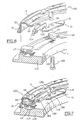
- These braking means consist of at least one tongue 51 which is a metal braking tongue and elastic which is fixed by riveting screwing, bolting etc. to the inner radial periphery, of transverse orientation, 110 pressure plate 1.
- One end of the tongue 51 is brought to fixation by the pressure plate 1, while that the second end of the tongue 51 cooperates with the ramp ring 32 being displaced circumferentially by report at the first end.
- the brake tongue 51 extends tangentially with respect to a circumference of the assembly and it has a protrusion 52 to cooperate friction with one of the ramps 32 vis-à-vis, the body of the tongue 51 extending for the most part under the ramp 32.
- the protuberance 52 belongs to the second end of the tongue 51 and is of transverse orientation or radial.
- the adjustment ring 100 comprising the ramps 32, the support means 3, the flange 33 and the toothing 31 is pinched axially at a ramp 32, more precisely here at level of the ramp 32 located next to the cassette 30, between the brake tongue 51, which is here axially elastic, and the corresponding pad 13.
- the elasticity of the tongue 51 depends on the length of it.
- the body 112 of the brake tongue 51 is a sheet metal part that extends globally in a plane transversal perpendicular to the X-X axis while being slightly angled so that its first free end has the protuberance 52 which extends radially outwards to extend facing the rear axial face, of transverse orientation, 116 of the corresponding ramp 32, who thus has a dual function and thus cooperates with one of the pads 13 and with the brake tongue 31.
- the other tangential end 118 of the body 112 of the brake tongue 51 namely the first end of the tongue 51, is the part of the tongue ensuring its fixing on the portion 110 of the pressure plate 1.
- a rivet 120 passes through the portion 110 and the end 118 to press the latter axially towards the front against the transverse orientation face 120 of the annular portion 110 of the pressure plate 1.
- the rivets 120 are replaced by other fasteners, screws etc.
- the tongue of braking 51 is always globally tangential orientation but it is radial action, that is to say that its second free end 114 has a protrusion 152 which is in elastic support against the portion vis-à-vis the edge radially internal peripheral 130 of the ramp 32 corresponding.
- the protuberance 152 preferably has a profile curved axially oriented cylinder whose convexity cooperates with the radially inner peripheral edge 130 of the ramp 32, the axial width, that is to say the height in considering Figures 6 and 7, the protuberance 52 being designed in such a way that the latter always cooperates with the edge 130 regardless of the angular position of the ring of setting 100, that is to say regardless of the position axial axis of the latter with respect to the pressure plate 1.
- the teeth 31 may belong to a intermediate piece wedged in translation on the lid and linked in rotation to the ring 100 while allowing movement axial of the ring.
- tabs 10 of the same game having an extension for pinching the intermediate piece linked to the ring by a tenon-mortise type connection or by tabs of the type of the tabs 10.
- the invention is applicable to a mechanism of the type of that described in document FR-A-2 424 442 in which the diaphragm has a peripheral lug received in a obviously a drum connected by a spring clutch unidirectional to the worm.
- cassette 30 can be replaced by a system drum, worm and axle carried by the lid as described in document FR-A-2 424 442 to which reference will be made for more details.
- the brake tongue can act on the ramps cooperating with counter-ramps reported on the plateau of pressure as described in FR-A-2 424 442.
- the tongue can therefore act on the outer periphery of the plateau of pressure.
- the chocks are inserted axially between stop tabs 5, that has the bottom 21 of the lid 2 at its inner periphery, and the fingers 42 of the diaphragm.
- Ring 8 has at its inner periphery a bead (no reference) for contact with the inner periphery of the fingers 42.
- the ring 8 protects the cassette 30 before mounting the clutch mechanism on the reaction plate or piece integral with the reaction plate.
- the mounting of the ring 8 between the legs 5 and the fingers 42, is made in particular by rotating the ring 8 using one or more tools engaging with holes 9 made in the ring.
- the disassembly of the ring 8 is achieved by a rotation reverse.
- the lid 2 has three dwellings of which two (no references) are visible in Figure 1.
- the dwellings are made on the outer periphery of the 2.
- One of the dwellings has an open bottom for the mounting the cassette 30.
- the lid has on both sides of the holes 47 holes for the assembly of balancing rivets.
- the diaphragm is pivotally mounted on the cover 2 using balusters or any other means of support the secondary support 25.
- the brake tongue 51 of Figure 5 can be interposed axially by through its protuberance 52, between the studs 13 and the ramps 32 to brake the ring.
- ring 8 The presence of ring 8 is not obligatory. So the bottom of the lid can be extended inward for forming an abutment, offset axially with respect to the support primary and in the opposite direction to the pressure plate.
- the cassette can have another form as described for example in the document PCT / FR99 / 00261 filed February 5, 1998.
- the elastic member can form on its own support of the cassette.
- the catch-up spring can be arranged out of the cassette being for example implanted between a stud and a ramp.
- the housing of the lid may constitute the cassette support.
Landscapes
- Engineering & Computer Science (AREA)
- General Engineering & Computer Science (AREA)
- Mechanical Engineering (AREA)
- Mechanical Operated Clutches (AREA)
Claims (12)
- Kupplungsmechanismus, umfassend einen Deckel (2), eine Druckplatte (1), die drehfest mit dem Deckel (2) verbunden ist, wobei sie sich im Verhältnis zu diesem axial verschieben kann, an der Druckplatte (1) angebrachte Auflagemittel (3), axial wirksame Einrückmittel (4, 41), die zwischen dem Deckel (2) und den Auflagemitteln (3) wirken, und eine Verschleißnachstellvorrichtung, die einerseits drehfest mit einer Außenzahnung (31) verbundene und zwischen der Druckplatte (1) und den Auflagemitteln (3) angeordnete Rampenmittel (100) mit Rampen (32) umfasst, um eine Druckplatte (1, 100) mit veränderlicher Dicke zwischen ihrer Reibfläche (11) und den Auflagemitteln (3) zu bilden, und die andererseits eine am Deckel (2) angebrachte Kassette (30) umfasst, die eine Schnecke (106) enthält, die mit der drehfest mit den Rampenmitteln mit Rampen (32) verbundenen Zahnung (31) zusammenwirkt, wobei die Auflagemittel (3) und die Rampen (32) als ein an der Druckplatte (1) angebrachtes einziges ringförmiges Teil (100) ausgeführt sind, dadurch gekennzeichnet, dass er wenigstens eine elastische Bremszunge (51) umfasst, die an der Druckplatte (1) angebracht ist und die mit dem Ring (100) mit Rampen (32) zusammenwirkt, damit sich die Rampen (32) im Falle von axialen Schwingungen oder bei einem Überweg der Einrückmittel (4, 41) beim Ausrücken nicht drehen und damit keine Verschleißnachstellung stattfindet.
- Kupplungsmechanismus nach dem vorangehenden Anspruch, dadurch gekennzeichnet, dass die Bremszunge (51) am inneren Umfang (110) der Druckplatte (1) befestigt ist und dass sie sich entlang einer im Verhältnis zu einem Kreisumfang des Mechanismus insgesamt tangentialen Richtung erstreckt.
- Mechanismus nach dem vorangehenden Anspruch, dadurch gekennzeichnet, dass eines (114) der tangentialen Enden der Bremszunge (51) eine Ausstülpung (52) umfasst, die mit einem gegenüberliegenden Abschnitt des Rampenrings mit Rampen (32) zusammenwirkt.
- Mechanismus nach Anspruch 3, dadurch gekennzeichnet, dass sich die Ausstülpung (52) radial nach außen erstreckt und mit der gegenüberliegenden axialen Fläche (116) einer der Rampen (32) des Rampenrings (100) mit Rampen (32) zusammenwirkt.
- Mechanismus nach dem vorangehenden Anspruch, dadurch gekennzeichnet, dass die Ausstülpung (52) in Anlage an der besagten axialen Fläche (116) einer der Rampen (32) elastisch beaufschlagt wird, um den Rampenring (100) zwischen der Bremszunge (51) und dem gegenüberliegenden Abschnitt der Druckplatte (1, 13) axial einzuspannen.
- Mechanismus nach Anspruch 3, dadurch gekennzeichnet, dass sich die Ausstülpung (52) tangential erstreckt und mit einer inneren Umfangskante (130) des Rampenrings (100) mit Rampen (32) zusammenwirkt.
- Mechanismus nach dem vorangehenden Anspruch, dadurch gekennzeichnet, dass die besagte Kante die innere Umfangskante (130) einer der Rampen (32) des Rampenrings (100) ist.
- Mechanismus nach Anspruch 6, dadurch gekennzeichnet, dass die Ausstülpung (52) in Anlage an der besagten Innenkante (130) elastisch beaufschlagt wird.
- Mechanismus nach dem vorangehenden Anspruch, dadurch gekennzeichnet, dass die Ausstülpung (52) einen gewölbten Wirkabschnitt umfasst, dessen konvexe Fläche mit dem besagten Abschnitt (116, 130) des Rampenrings (100) mit Rampen (32) zusammenwirkt.
- Mechanismus nach Anspruch 3, dadurch gekennzeichnet, dass die Bremszunge (51) an der Druckplatte (1) durch Aufnieten (120) befestigt ist.
- Mechanismus nach dem vorangehenden Anspruch, dadurch gekennzeichnet, dass der Körper des Befestigungsniets (126) der Bremszunge (51) parallel zur Achse (X-X) des Mechanismus verläuft und sich durch ein Loch erstreckt, das im Mittelteil (112) der Bremszunge (51) ausgebildet ist, der als eine einer gegenüberliegenden axialen Fläche (122) der Druckplatte (1, 110) zugekehrte Platte gestaltet ist.
- Mechanismus nach dem vorangehenden Anspruch, dadurch gekennzeichnet, dass das andere tangentiale Ende (118) der Bremszunge (51) mit einem Vorsprung (13) der Druckplatte (1) zusammenwirkt, um die Bremszunge winklig um die Achse des Niets (120) zu positionieren.
Applications Claiming Priority (5)
| Application Number | Priority Date | Filing Date | Title |
|---|---|---|---|
| FR9801769A FR2775038B1 (fr) | 1998-02-13 | 1998-02-13 | Mecanisme d'embrayage, notamment pour vehicule automobile |
| FR9801769 | 1998-02-13 | ||
| FR9815533 | 1998-12-09 | ||
| FR9815533A FR2775040B1 (fr) | 1998-02-13 | 1998-12-09 | Mecanisme d'embrayage pour vehicule automobile comportant un dispositif perfectionne de rattrapage d'usure des garnitures de friction |
| PCT/FR1999/000337 WO1999041517A1 (fr) | 1998-02-13 | 1999-02-15 | Mecanisme d'embrayage pour vehicule automobile comportant un dispositif perfectionne de rattrapage d'usure des garnitures de friction |
Publications (2)
| Publication Number | Publication Date |
|---|---|
| EP0975884A1 EP0975884A1 (de) | 2000-02-02 |
| EP0975884B1 true EP0975884B1 (de) | 2003-07-30 |
Family
ID=26234135
Family Applications (1)
| Application Number | Title | Priority Date | Filing Date |
|---|---|---|---|
| EP99903763A Expired - Lifetime EP0975884B1 (de) | 1998-02-13 | 1999-02-15 | Kupplungsmechanismus für ein kraftfahrzeug, mit einer verschleiss-nachstelleinrichtung für die reibbeläge |
Country Status (6)
| Country | Link |
|---|---|
| US (1) | US6227341B1 (de) |
| EP (1) | EP0975884B1 (de) |
| DE (1) | DE19980451B4 (de) |
| ES (1) | ES2205767T3 (de) |
| FR (1) | FR2775040B1 (de) |
| WO (1) | WO1999041517A1 (de) |
Families Citing this family (9)
| Publication number | Priority date | Publication date | Assignee | Title |
|---|---|---|---|---|
| FR2809147B1 (fr) * | 2000-05-19 | 2002-09-06 | Valeo | Embrayage a friction a dispositif de rattrapage de jeu pilote pour vehicule automobile |
| FR2816683B1 (fr) * | 2000-11-10 | 2003-01-10 | Valeo | Dispositif de rattrapage automatique d'usure dans un embrayage a friction, en particulier pour vehicule automobile |
| US6786312B1 (en) * | 2002-12-16 | 2004-09-07 | Lewis L. Osborne | Motorcycle combination clutch and brake system |
| EP1972816B1 (de) * | 2007-03-22 | 2011-07-13 | Schaeffler Technologies AG & Co. KG | Selbstnachstellende Reibungskupplung sowie Doppelkupplung mit einer solchen Reibungskupplung |
| DE102008012864A1 (de) * | 2007-03-22 | 2008-09-25 | Luk Lamellen Und Kupplungsbau Beteiligungs Kg | Tellerfederhebelbaugruppe zum Betätigen einer Reibungskupplung mit integriertem Verschleißausgleich sowie selbstnachstellende Reibungskupplung |
| EP2063145B1 (de) * | 2007-11-21 | 2014-05-28 | ZF Friedrichshafen AG | Druckplattenbaugruppe |
| JP2009228109A (ja) * | 2008-03-25 | 2009-10-08 | Nippon Mining & Metals Co Ltd | 黄銅鉱を含有する硫化銅鉱の浸出方法 |
| FR3060684B1 (fr) * | 2016-12-19 | 2020-07-03 | Valeo Embrayages | Organe de rattrapage d'usure pour un mecanisme d'embrayage, notamment pour vehicule automobile |
| CN113062935B (zh) * | 2021-04-22 | 2022-12-06 | 合肥工业大学 | 一种多摩擦片式纯线控制动器 |
Family Cites Families (24)
| Publication number | Priority date | Publication date | Assignee | Title |
|---|---|---|---|---|
| US3752286A (en) * | 1972-02-24 | 1973-08-14 | Dana Corp | Self-adjusting clutch |
| DE2402114A1 (de) | 1973-01-22 | 1974-08-01 | Illinois Tool Works | Verfahren und vorrichtung zum umformen ineinandersteckbarer kunststoffbehaelter in nicht ineinandersteckbare behaelter |
| GB1567019A (en) * | 1976-03-24 | 1980-05-08 | Automotive Prod Co Ltd | Friction clutches |
| US4191285A (en) | 1977-09-06 | 1980-03-04 | Borg-Warner Corporation | Wear compensator for Belleville spring clutch |
| US4228883A (en) | 1978-04-27 | 1980-10-21 | Borg-Warner Corporation | Automatic wear adjuster for Belleville spring clutches |
| US5029687A (en) * | 1989-01-18 | 1991-07-09 | Kabushiki Kaisha Daikin Seisakusho | Self adjuster for pull-type clutch |
| JPH041730U (de) * | 1989-12-29 | 1992-01-08 | ||
| JPH0532665Y2 (de) * | 1990-03-14 | 1993-08-20 | ||
| US5634541A (en) * | 1992-03-05 | 1997-06-03 | Luk Lamellen Und Kupplungsbau Gmbh | Automatically adjustable friction clutch |
| US5251737A (en) * | 1992-03-31 | 1993-10-12 | Dana Corporation | Self-adjusting means and method for friction clutches |
| US5320205A (en) * | 1992-11-12 | 1994-06-14 | Dana Corporation | Wear adjustment for a clutch |
| FR2735823B1 (fr) * | 1995-06-22 | 1997-09-05 | Valeo | Embrayage a friction a dispositif de rattrapage de jeu, notamment pour vehicule automobile |
| GB9518991D0 (en) * | 1995-09-16 | 1995-11-15 | Automotive Products Plc | Automatically adjusting clutch |
| FR2739158B1 (fr) * | 1995-09-21 | 1997-11-28 | Valeo | Embrayage a friction a dispositif de rattrapage de jeu, notamment pour vehicule automobile |
| FR2739159B1 (fr) * | 1995-09-21 | 1997-11-28 | Valeo | Moyens a rampes pour dispositif de rattrapage de jeu destine a equiper un embrayage a friction, notamment pour vehicule automobile |
| US5894916A (en) * | 1996-05-24 | 1999-04-20 | Luk Lamellen Und Kupplungbau Gmbh | Friction clutch |
| FR2753506B1 (fr) * | 1996-09-17 | 1998-12-04 | Valeo | Embrayage a friction, en particulier pour vehicule automobile, comportant un dispositif de rattrapage d'usure |
| US5944157A (en) * | 1996-09-17 | 1999-08-31 | Valeo | Friction clutch, in particular for a motor vehicle, including a wear compensating device |
| FR2753504B1 (fr) * | 1996-09-17 | 1998-12-04 | Valeo | Embrayage a friction a dispositif de rattrapage d'usure, en particulier pour vehicule automobile |
| FR2753503B1 (fr) | 1996-09-17 | 1998-12-04 | Valeo | Embrayage a friction a dispositif de rattrapage d'usure, notamment pour vehicule automobile |
| DE19738895A1 (de) * | 1997-09-05 | 1999-03-18 | Mannesmann Sachs Ag | Druckplattenbaugruppe |
| JP2001522444A (ja) * | 1998-02-05 | 2001-11-13 | ヴァレオ | 摩擦クラッチ機構 |
| FR2775038B1 (fr) * | 1998-02-13 | 2000-10-27 | Valeo | Mecanisme d'embrayage, notamment pour vehicule automobile |
| FR2783580B1 (fr) * | 1998-09-23 | 2000-11-24 | Valeo | Mecanisme d'embrayage, notamment pour vehicule automobile |
-
1998
- 1998-12-09 FR FR9815533A patent/FR2775040B1/fr not_active Expired - Fee Related
-
1999
- 1999-02-15 EP EP99903763A patent/EP0975884B1/de not_active Expired - Lifetime
- 1999-02-15 US US09/403,229 patent/US6227341B1/en not_active Expired - Lifetime
- 1999-02-15 ES ES99903763T patent/ES2205767T3/es not_active Expired - Lifetime
- 1999-02-15 WO PCT/FR1999/000337 patent/WO1999041517A1/fr not_active Ceased
- 1999-02-15 DE DE19980451T patent/DE19980451B4/de not_active Expired - Fee Related
Also Published As
| Publication number | Publication date |
|---|---|
| ES2205767T3 (es) | 2004-05-01 |
| DE19980451T1 (de) | 2000-05-11 |
| DE19980451B4 (de) | 2010-07-01 |
| US6227341B1 (en) | 2001-05-08 |
| FR2775040A1 (fr) | 1999-08-20 |
| WO1999041517A1 (fr) | 1999-08-19 |
| FR2775040B1 (fr) | 2000-07-21 |
| EP0975884A1 (de) | 2000-02-02 |
Similar Documents
| Publication | Publication Date | Title |
|---|---|---|
| EP0769633B1 (de) | Rampenvorrichtung für eine Nachstellvorrichtung einer Reibungskupplung, insbesondere für Kraftfahrzeuge | |
| EP0237373B1 (de) | Fahrzeug-Schwungrad | |
| EP0857262B1 (de) | Reibungskupplung für kraftfahrzeuge mit einer verschleiss-nachstelleinrichtung | |
| EP0975884B1 (de) | Kupplungsmechanismus für ein kraftfahrzeug, mit einer verschleiss-nachstelleinrichtung für die reibbeläge | |
| EP0972142B1 (de) | Reibungskupplungsmechanismus mit einer nachstellvorrichtung, insbesondere für kraftfahrzeuge | |
| EP0975883B1 (de) | Kupplung mit nachstellvorrichtung und auswuchtvorrichtung | |
| FR2718806A1 (fr) | Plateau de réaction pour embrayage à friction, notamment pour véhicule automobile. | |
| FR2768786A1 (fr) | Embrayage a friction | |
| EP1082549B1 (de) | Reibungskupplung mit einer verschleiss-nachstelleinrichtung ,insbesondere für kraftfahrzeuge | |
| EP0975882B1 (de) | Kupplungsvorrichtung, insbesondere für kraftfahrzeuge | |
| FR2847625A1 (fr) | Embrayages a friction a dispositif de rattrapage d'usure des garnitures de friction, en particulier pour vehicule automobile | |
| EP0972144B1 (de) | Reibungskupplungsmechanismus mit einer nachstellvorrichtungseinheit | |
| FR2703743A1 (fr) | Mécanisme d'embrayage, notamment pour véhicule automobile. | |
| EP0678169B1 (de) | Kupplungsanordnung insbesondere für kraftfahrzeuge | |
| EP0972143A1 (de) | Kupplungsmechanismus mit einer nachstellvorrichtungseinheit | |
| FR2785954A1 (fr) | Embrayage a friction, notamment pour vehicule automobile comportant un dispositif perfectionne de rattrapage d'usure | |
| FR2783580A1 (fr) | Mecanisme d'embrayage, notamment pour vehicule automobile | |
| EP0916032B1 (de) | Reibungskupplung mit nachstellvorrichtung | |
| FR2786832A1 (fr) | Mecanisme d'embrayage a friction | |
| EP0926374B1 (de) | Reibungskupplung mit einer Verschleiss-Nachstelleinrichtung, insbesondere für Kraftfahrzeuge | |
| FR2786831A1 (fr) | Mecanisme d'embrayage a friction | |
| FR2787157A1 (fr) | Mecanisme d'embrayage a rattrapage d'usure a cassette | |
| EP1015784A1 (de) | Reibungskupplung mit nachstellvorrichtung | |
| WO2000000754A1 (fr) | Mecanisme d'embrayage, pour embrayage a friction | |
| FR2798972A1 (fr) | Embrayage a friction a dispositif de rattrapage d'usure des garnitures de friction, en particulier pour vehicule automobile |
Legal Events
| Date | Code | Title | Description |
|---|---|---|---|
| PUAI | Public reference made under article 153(3) epc to a published international application that has entered the european phase |
Free format text: ORIGINAL CODE: 0009012 |
|
| 17P | Request for examination filed |
Effective date: 19991023 |
|
| AK | Designated contracting states |
Kind code of ref document: A1 Designated state(s): ES FR GB IT |
|
| GRAH | Despatch of communication of intention to grant a patent |
Free format text: ORIGINAL CODE: EPIDOS IGRA |
|
| RAP1 | Party data changed (applicant data changed or rights of an application transferred) |
Owner name: VALEO |
|
| GRAH | Despatch of communication of intention to grant a patent |
Free format text: ORIGINAL CODE: EPIDOS IGRA |
|
| RAP1 | Party data changed (applicant data changed or rights of an application transferred) |
Owner name: VALEO EMBRAYAGES S.A.S. |
|
| GRAA | (expected) grant |
Free format text: ORIGINAL CODE: 0009210 |
|
| AK | Designated contracting states |
Designated state(s): ES FR GB IT |
|
| REG | Reference to a national code |
Ref country code: GB Ref legal event code: FG4D Free format text: NOT ENGLISH |
|
| REG | Reference to a national code |
Ref country code: FR Ref legal event code: TP |
|
| GBT | Gb: translation of ep patent filed (gb section 77(6)(a)/1977) |
Effective date: 20031029 |
|
| REG | Reference to a national code |
Ref country code: ES Ref legal event code: FG2A Ref document number: 2205767 Country of ref document: ES Kind code of ref document: T3 |
|
| PLBE | No opposition filed within time limit |
Free format text: ORIGINAL CODE: 0009261 |
|
| STAA | Information on the status of an ep patent application or granted ep patent |
Free format text: STATUS: NO OPPOSITION FILED WITHIN TIME LIMIT |
|
| 26N | No opposition filed |
Effective date: 20040504 |
|
| REG | Reference to a national code |
Ref country code: FR Ref legal event code: PLFP Year of fee payment: 18 |
|
| REG | Reference to a national code |
Ref country code: FR Ref legal event code: PLFP Year of fee payment: 19 |
|
| PGFP | Annual fee paid to national office [announced via postgrant information from national office to epo] |
Ref country code: FR Payment date: 20170228 Year of fee payment: 19 |
|
| PGFP | Annual fee paid to national office [announced via postgrant information from national office to epo] |
Ref country code: GB Payment date: 20170214 Year of fee payment: 19 |
|
| PGFP | Annual fee paid to national office [announced via postgrant information from national office to epo] |
Ref country code: ES Payment date: 20170228 Year of fee payment: 19 Ref country code: IT Payment date: 20170217 Year of fee payment: 19 |
|
| GBPC | Gb: european patent ceased through non-payment of renewal fee |
Effective date: 20180215 |
|
| REG | Reference to a national code |
Ref country code: FR Ref legal event code: ST Effective date: 20181031 |
|
| PG25 | Lapsed in a contracting state [announced via postgrant information from national office to epo] |
Ref country code: FR Free format text: LAPSE BECAUSE OF NON-PAYMENT OF DUE FEES Effective date: 20180228 Ref country code: IT Free format text: LAPSE BECAUSE OF NON-PAYMENT OF DUE FEES Effective date: 20180215 Ref country code: GB Free format text: LAPSE BECAUSE OF NON-PAYMENT OF DUE FEES Effective date: 20180215 |
|
| REG | Reference to a national code |
Ref country code: ES Ref legal event code: FD2A Effective date: 20190801 |
|
| PG25 | Lapsed in a contracting state [announced via postgrant information from national office to epo] |
Ref country code: ES Free format text: LAPSE BECAUSE OF NON-PAYMENT OF DUE FEES Effective date: 20180216 |