EP0976013B1 - Soupape de reglage de pression - Google Patents
Soupape de reglage de pression Download PDFInfo
- Publication number
- EP0976013B1 EP0976013B1 EP98920512A EP98920512A EP0976013B1 EP 0976013 B1 EP0976013 B1 EP 0976013B1 EP 98920512 A EP98920512 A EP 98920512A EP 98920512 A EP98920512 A EP 98920512A EP 0976013 B1 EP0976013 B1 EP 0976013B1
- Authority
- EP
- European Patent Office
- Prior art keywords
- pressure
- regulating valve
- valve
- inlet
- control
- Prior art date
- Legal status (The legal status is an assumption and is not a legal conclusion. Google has not performed a legal analysis and makes no representation as to the accuracy of the status listed.)
- Expired - Lifetime
Links
- 230000001105 regulatory effect Effects 0.000 title claims description 8
- 238000007789 sealing Methods 0.000 claims description 18
- 238000011144 upstream manufacturing Methods 0.000 claims description 13
- XEEYBQQBJWHFJM-UHFFFAOYSA-N iron Substances [Fe] XEEYBQQBJWHFJM-UHFFFAOYSA-N 0.000 claims description 7
- 229910052742 iron Inorganic materials 0.000 claims description 4
- 239000012080 ambient air Substances 0.000 claims 1
- 230000005540 biological transmission Effects 0.000 description 3
- 238000010586 diagram Methods 0.000 description 3
- 238000012549 training Methods 0.000 description 3
- 230000009471 action Effects 0.000 description 2
- 230000008901 benefit Effects 0.000 description 2
- 238000013461 design Methods 0.000 description 2
- 238000011161 development Methods 0.000 description 2
- 238000006073 displacement reaction Methods 0.000 description 2
- 239000012530 fluid Substances 0.000 description 2
- 239000002245 particle Substances 0.000 description 2
- 241001270131 Agaricus moelleri Species 0.000 description 1
- 238000005299 abrasion Methods 0.000 description 1
- 238000013459 approach Methods 0.000 description 1
- 230000000903 blocking effect Effects 0.000 description 1
- 238000010276 construction Methods 0.000 description 1
- 230000008878 coupling Effects 0.000 description 1
- 238000010168 coupling process Methods 0.000 description 1
- 238000005859 coupling reaction Methods 0.000 description 1
- 230000007423 decrease Effects 0.000 description 1
- 230000000694 effects Effects 0.000 description 1
- 230000002349 favourable effect Effects 0.000 description 1
- 230000002706 hydrostatic effect Effects 0.000 description 1
- 230000003993 interaction Effects 0.000 description 1
- 238000000034 method Methods 0.000 description 1
- 230000008569 process Effects 0.000 description 1
Images



Classifications
-
- G—PHYSICS
- G05—CONTROLLING; REGULATING
- G05D—SYSTEMS FOR CONTROLLING OR REGULATING NON-ELECTRIC VARIABLES
- G05D16/00—Control of fluid pressure
- G05D16/20—Control of fluid pressure characterised by the use of electric means
- G05D16/2006—Control of fluid pressure characterised by the use of electric means with direct action of electric energy on controlling means
- G05D16/2013—Control of fluid pressure characterised by the use of electric means with direct action of electric energy on controlling means using throttling means as controlling means
- G05D16/2024—Control of fluid pressure characterised by the use of electric means with direct action of electric energy on controlling means using throttling means as controlling means the throttling means being a multiple-way valve
-
- F—MECHANICAL ENGINEERING; LIGHTING; HEATING; WEAPONS; BLASTING
- F16—ENGINEERING ELEMENTS AND UNITS; GENERAL MEASURES FOR PRODUCING AND MAINTAINING EFFECTIVE FUNCTIONING OF MACHINES OR INSTALLATIONS; THERMAL INSULATION IN GENERAL
- F16K—VALVES; TAPS; COCKS; ACTUATING-FLOATS; DEVICES FOR VENTING OR AERATING
- F16K31/00—Actuating devices; Operating means; Releasing devices
- F16K31/02—Actuating devices; Operating means; Releasing devices electric; magnetic
-
- Y—GENERAL TAGGING OF NEW TECHNOLOGICAL DEVELOPMENTS; GENERAL TAGGING OF CROSS-SECTIONAL TECHNOLOGIES SPANNING OVER SEVERAL SECTIONS OF THE IPC; TECHNICAL SUBJECTS COVERED BY FORMER USPC CROSS-REFERENCE ART COLLECTIONS [XRACs] AND DIGESTS
- Y10—TECHNICAL SUBJECTS COVERED BY FORMER USPC
- Y10T—TECHNICAL SUBJECTS COVERED BY FORMER US CLASSIFICATION
- Y10T137/00—Fluid handling
- Y10T137/8593—Systems
- Y10T137/86493—Multi-way valve unit
- Y10T137/86574—Supply and exhaust
- Y10T137/86622—Motor-operated
-
- Y—GENERAL TAGGING OF NEW TECHNOLOGICAL DEVELOPMENTS; GENERAL TAGGING OF CROSS-SECTIONAL TECHNOLOGIES SPANNING OVER SEVERAL SECTIONS OF THE IPC; TECHNICAL SUBJECTS COVERED BY FORMER USPC CROSS-REFERENCE ART COLLECTIONS [XRACs] AND DIGESTS
- Y10—TECHNICAL SUBJECTS COVERED BY FORMER USPC
- Y10T—TECHNICAL SUBJECTS COVERED BY FORMER US CLASSIFICATION
- Y10T137/00—Fluid handling
- Y10T137/8593—Systems
- Y10T137/87169—Supply and exhaust
- Y10T137/87217—Motor
Definitions
- the present invention relates to a proportional pressure control valve of the 3/2-way type, consisting of a valve housing, which has a control pressure chamber and with a Pressure medium supply line, with one with the consumer in Connected working pressure line and a pressure sump line and with at least two f-stops with defined or definable flow resistance, of which two aperture stages based on the principle of hydraulic Half bridge are coupled together.
- DE-C 44 26 152 describes an electromagnetic Pressure control valve, especially for switching pressure control of automatic automotive transmissions that have a valve housing and one which can be actuated by a magnetic armature and with this connected control spool, the connections from a pressure medium inlet to a consumer connection or a return or tank controls.
- the spool is in a rear and in a front bearing in Valve housing mounted and preloaded via an adjusting spring.
- US 5,135,027 which represents the closest prior art forms, describes a pressure control valve with a connection for a pressure line, a connection for a working pressure line, a connection for an outlet line to Ambient pressure and at least two orifice steps with defined or definable flow resistance, two of which Aperture levels variable and under mechanical or hydraulic Action according to the principle of the hydraulic half-bridge are coupled.
- the two variable aperture levels are the inlet and outlet orifice of a control pressure chamber provided and each have a closure body, wherein the closure body of the inlet panel is designed as a ball is and the closure body of the outlet panel is a has a conical sealing surface.
- the object of the present invention is to provide a proportional pressure control valve, especially for switching pressure control of automatic automotive transmissions to create at which the minimum working pressure is almost zero and the leakage flow of the pressure medium in the end position of the Control spool with minimal working pressure Zero is minimized and which is an adjustment of the flow properties of the valve to the respective operating conditions allows.
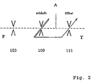
- the pressure control valve is a coupled throttle or Aperture system trained (in the following is representative the term aperture is used for choke or orifice).
- the coupled aperture system consists of two mechanical, or hydraulically coupled control orifices. These control panels are connected according to the principle of the hydraulic half bridge. In front of the two control panels there can be a fixed panel be upstream.
- This coupled aperture system has three connections: a pressure medium supply line (connection P), a working pressure line to the consumer (connection A) and a pressure sump line to the pressure sump (Connection T).
- Port P is on the input side the first control panel or the fixed panel, the connection A is z. B. arranged between the two control panels and the connection T is on the output side behind the second control panel.
- Each of the orifices represents a flow resistance
- the two control panels are included adjustable flow resistances.
- the principle of operation this pressure-controlled valve works in the same way as one electrical voltage divider with two coupled adjustable Sliding resistors or with an upstream Fixed resistor and two coupled adjustable sliding resistors.
- Each of the orifices causes a certain drop in pressure.
- On the input side of the first control orifice Fixed orifice prevails inlet pressure, while on the outlet side ambient pressure prevails after the second control orifice.
- the Pressure between the two regulating orifices depends on the opening the orifices can be adjusted between ambient pressure and inlet pressure.
- the two control panels form inlet and Outlet opening of a control pressure chamber and each have a closure body for opening and closing the panels on.
- the closure body of the inlet panel as a ball and the closure body of the outlet panel designed as a cylinder.
- the inflow and outflow characteristics of the two control orifices to the respective operating conditions of the valve be set as best as possible.
- the type of each panel as a seat valve and thus the Shape of the sealing surface as well as the pressure gain each aperture individually optimized.
- the two regulating orifices are by a spool coupled.
- the control spool moves in one direction Cross section of the inlet panel enlarged and at the same time that of the exhaust aperture is reduced.
- Cross section of the inlet panel enlarged and at the same time that of the exhaust aperture is reduced.
- When moving the Control spool in the opposite direction changes the cross sections in reverse. This corresponds to the principle of operation a hydraulic half bridge. It can depending on the design of the coupling, positions of the control spool give those with an aperture already fully open is while the other is not yet completely closed is (negative coverage of the control edges). With a possible In the operating state, the inlet panel is already complete opened and the outlet cover is not yet completely closed.
- the system of two coupled control panels is reduced
- the system with two coupled control panels has opposite the system with a control panel and a fixed panel the advantage that when the outlet cover is fully open the flow is not as in the system of fixed and control orifice is maximum, but by closing the inlet control panel is minimized to zero.
- the operating status "Fully open outlet cover” corresponds in both systems and in the reduced system with fixed inlet panel and adjustable outlet orifice to the minimum control pressure.
- adjustable Control pressure by locking the inlet to ambient pressure minimized beyond the outlet, while in System of fixed and control orifice a finite residual pressure remains due to hydrodynamic effects.
- the middle one Flow is higher in the system of fixed and control orifice. This brings a higher power loss compared to System with two coupled control panels. Another The advantage is that due to the lower maximum Flow through the pump to provide the inlet pressure can be dimensioned weaker.
- Pressure control valve as a system of two mechanically or hydraulically coupled, variable aperture stages. This is advantageously characterized by a simple, inexpensive construction.
- valve is constructed as a system of three orifice stages, with a first pressure-side, fixed aperture stage and two coupled variable aperture stops, creating several Adjustment options for the flow properties exist than in the aforementioned training of only two variables F-stops.
- This pressure control valve according to the invention is advantageous to control the hydraulic pressure to actuate Gear shifts used.
- the two variable aperture levels are housed in one component.
- the inlet orifice in the control pressure chamber is in Form from a bore forming an inlet opening a valve housing shown with a closure body can be covered.
- the outlet cover is in shape a seat valve formed in which an axial wall surface of the valve housing a sealing or end face of a Closure body, in particular an anchor rod, covered.
- a pin-shaped spool that is in axial Direction to the anchor rod can Slide the shutter body of the inlet panel out of its seat.
- the control slide puts the two panels coupled one, by making the cross section of the intake panel by covering the inlet opening area with defines the closure body and on the other hand the outlet panel surface by the distance between the axial Wall surface and the end face determined.
- the closure body does not have to be in one piece with the control slide or the anchor rod connected, d. i.e., the Components are made up of two or more parts.
- the current or the pressure of the pressure medium leaves it on the control slide and guide him when the spool is withdrawn after this. It is advantageous for inclusion of the closure body, especially if it is not is integrally connected to the spool, a cage provided, which also for the targeted adjustment of the inflow characteristic can be used.
- the inlet opening is part of the end face of a forms cylindrical valve chamber, which has this Area acting force an axial component, so that open this inlet by axially moving the control spool and thus removing the closure body from its Seat in the inlet opening at different pressures a hydrostatic holding force in the control pressure chamber and inlet is to be overcome.
- This holding force results from the difference of the mean pressure in the inlet and the Control pressure chamber multiplied by the area of the inlet opening. Therefore the inlet opening is not dimensioned too large, to get an acceptable valve identifier.
- the axial force on the armature results as the sum of the product of an average pressure in the control pressure chamber, which approximately the working pressure in Corresponds to the consumer, and the free anchor surface (full Anchor area minus cross-sectional area of the spool) and the force caused by the dynamic pressure on the Closure body.
- the closure body is advantageously in one piece trained with the spool.
- the pressure control valve is preferably actuated magnetically.
- the actuating force of this pressure control valve is included the force that an electromagnet induces on the magnetic Exercises moment of a soft iron anchor.
- the soft iron anchor is advantageously pressed onto the anchor rod.
- the pressure control valve can also be a technical variant can be actuated piezoelectrically or pneumatically.
- three panels are housed in a discrete component.
- the three panels consist of one on the inlet side Fixed aperture and two coupled control panels together.
- the inlet-side fixed orifice can be used as an upstream Aperture, but also as a choke in the form of one or several holes.
- the paired Control orifices form the inlet and outlet of a control pressure chamber.
- the regulated inlet aperture is at least a radial inlet bore in cooperation through a valve housing represented with a control spool, which itself partly in the cylindrical, hollow control pressure chamber extends into it. This spool is within the Control pressure chamber axially movable over a certain length.
- the anchor rod and the control slide are preferably made in one piece.
- the inlet control orifice preferably has a plurality of radial ones Inlet bores in the valve housing on a Ring channel connected to the upstream fixed panel are.
- a sealing surface is provided on an end face of the anchor rod, this sealing surface with a corresponding Sealing surface on the valve housing interacts and thus enables a flat seat gasket with the best sealing properties.
- Pressure control valve advantageously designed such that the diameter of the pin-shaped spool is smaller than the diameter of the anchor rod.
- the pressure control valve in the first embodiment of the Invention acts as a 3/2-way valve with locking of the pressure medium in the pressure medium supply 2 for large working strokes.
- the function corresponds to that of a hydraulic half bridge.
- the pressure medium supply 2 preferably opens out via a axially arranged inlet bore in the control pressure chamber 7.
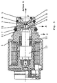
- the pressure control valve, the housing is denoted by 1, an electromagnet on the an anchor 13 in the direction of the axis A against the action a spring.
- the anchor 13 provides an anchor rod 10 the control spool 12.
- the control spool 12, the end face 6 designed as a sealing surface the anchor rod 10 connects is in the form of a pin executed, the closure body designed as a ball 5 slide out of its seat in the inlet opening 8 can.
- Anchor rod 10, control slide 12 and closure body 5 can be made in one, two, three or more pieces his. Closes in an end position of the pressure control valve the closure body 5 the bore of the inlet opening 8 of the pressure medium supply 2 in the control pressure chamber 7 Completely. In the other end position it is the control edge 11 of the end face 6 acting axially on the Wall surface 4 of the valve housing 1.
- the actuating forces for moving the control spool 12, d. H. for moving the closure body 5 from its seat in the inlet opening are small.
- the internal pressure feedback from the control pressure chamber 7 to the sealing surface 6 of the anchor rod acting as an anchor active surface 10 enables an uncomplicated control function.
- the Anchor room is like the conventional one in DE-C 44 26 152 described, installed in series seat valve depressurized.
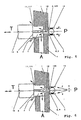
- valve designs shown which for the outlet 111 a cylindrical Provide flat-top closure body; the closure body 5 of the inlet aperture 109 are replaced by a ball formed as a seat valve. 7 and 8, the Closure body in the outlet 111 with a flat seat seal an additional, upstream truncated cone.
- 6 and 8 correspond essentially 5 and 7, but additionally have an upstream Fixed aperture 3.
Landscapes
- Physics & Mathematics (AREA)
- Fluid Mechanics (AREA)
- Engineering & Computer Science (AREA)
- General Physics & Mathematics (AREA)
- Automation & Control Theory (AREA)
- General Engineering & Computer Science (AREA)
- Mechanical Engineering (AREA)
- Control Of Fluid Pressure (AREA)
- Servomotors (AREA)
- Magnetically Actuated Valves (AREA)
Claims (18)
- Valve de réglage de pression comprenant un raccordement pour une conduite de pression (P), un raccordement pour une conduite de pression de travail (A) et un raccordement pour une conduite d'échappement (T) sur la pression environnante, et au moins deux étages d'ajutage ayant une résistance à l'écoulement définie ou pouvant être définie, parmi lesquels deux étages d'ajutage (109, 111) sont couplés de façon variable et sous influence mécanique ou hydraulique selon le principe du demi pont hydraulique et les deux étages d'ajutage variables sont prévus en qualité d'ajutages d'admission et d'échappement d'un espace de pression de réglage, et présentent chacun un corps obturateur, le corps obturateur de l'ajutage d'admission étant constitué par une bille (5) et le corps obturateur de l'ajutage d'échappement présentant une surface de fermeture étanche 6) possédant un siège plat, caractérisé en ce que le diamètre de la bille (5) est plus petit que le diamètre de la surface de joint étanche du siège plat.
- Valve de réglage de pression selon la revendication 1, caractérisée en ce qu'elle peut être actionnée par voie magnétique ou électromagnétique.
- Valve de réglage de pression selon la revendication 1, caractérisée en ce qu'elle peut être actionnée par voie piézoélectrique ou pneumatique.
- Valve de réglage de pression selon la revendication 1 ou la revendication 2, caractérisée en ce qu'il est prévu un électro-aimant comprenant une armature (13) et une tige d'armature (10), et la tige d'armature (10) coopère avec un poussoir de commande (12) en forme de tige, qui fait suite à la tige d'armature (10) dans la direction axiale et peut écarter le corps obturateur de l'ajutage d'admission de son siège et établit ainsi les deux ajutages dans un mode couplé.
- Valve de réglage de pression selon une des revendications précédentes, caractérisée en ce qu'elle est construite sous la forme d'un système de deux étages d'ajutage variables (109, 111) couplés sous influence mécanique ou hydraulique.
- Valve de réglage de pression selon une des revendications 1 à 4, caractérisée en ce qu'il est réalisé sous la forme d'un système de trois étages d'ajutage, comprenant un premier étage d'ajutage fixe, côté pression (103) et deux étages d'ajutage variables, couplés sous influence mécanique ou hydraulique (109, 111).
- Valve de réglage de pression selon une des revendications précédentes, caractérisée en ce que le corps obturateur (5) est réalisé en une seule pièce avec le poussoir de commande (12).
- Valve de réglage de pression selon une des revendications précédentes, caractérisée en ce que les deux étages d'ajutage variables sont logés dans un élément, l'ajutage d'admission étant formé dans l'espace de pression de réglage (7) sous la forme d'un perçage à travers le corps (1) de la valve, qui peut être recouvert par un corps obturateur, et l'ajutage d'échappement étant réalisé sous la forme d'une soupape à siège, par le fait qu'une surface de paroi axiale (4) du corps (1) de la valve recouvre une surface de joint étanche (6) du corps obturateur, le poussoir de commande (12) en forme de tige pouvant écarter le corps obturateur de l'ajutage d'admission de son siège et établissant ainsi les deux ajutages en mode couplé par le fait que, d'une part, il fixe la section de l'ajutage d'admission par recouvrement de la surface du perçage d'entrée avec le corps obturateur et, d'autre part, il détermine la surface de l'ajutage d'échappement par la distance entre la surface de paroi axiale (4) et la surface de joint étanche (6).
- Valve de réglage de pression selon une des revendications précédentes, caractérisée en ce que la tige d'armature (10) et le poussoir de commande (12) sont réalisés en deux pièces.
- Valve de réglage de pression selon la revendication 9, caractérisée en ce qu'une cage (14) est prévue pour recevoir le corps obturateur (5).
- Valve de réglage de pression selon une des revendications 4 à 8,caractérisée en ce que la tige d'armature (10) et le poussoir de commande (12) sont réalisés en une seule pièce.
- Valve de réglage de pression selon une des revendications 4 à 11, caractérisée en ce que sa force de réglage est développée par la force qu'un électro-aimant exerce sur le moment magnétique induit d'une armature en fer doux.
- Valve de réglage de pression selon une des revendications 4 à 12, caractérisée en ce que l'ajutage d'admission présente plusieurs perçages d'arrivée radiaux dans le corps (1) de la valve, qui sont reliés par un canal annulaire à un ajutage fixe placé en amont qui constitue le premier étage d'ajutage.
- Valve de réglage de pression selon une des revendications 4 à 13, caractérisée en ce que la surface de joint étanche (6) est prévue sur une face frontale de la tige d'armature (10).
- Valve de réglage de pression selon la revendication 14, caractérisée en ce que la région entre la surface frontale de la tige d'armature (10) et le poussoir de commande (12) est tronconique.
- Valve de réglage de pression selon une des revendications 4 à 15, caractérisée en ce que l'armature (13) est emmanchée à force sur la tige d'armature (10).
- Valve de réglage de pression selon une des revendications précitées, caractérisée en ce que le diamètre du poussoir de commande (12) en forme de tige est plus petit que le diamètre de la tige d'armature (10).
- Utilisation d'une valve de réglage de pression selon une des revendications précédentes pour le réglage de la pression hydraulique pour l'actionnement des éléments de changement de rapport d'une boíte de vitesses dans un véhicule automobile.
Applications Claiming Priority (5)
| Application Number | Priority Date | Filing Date | Title |
|---|---|---|---|
| DE19716135 | 1997-04-18 | ||
| DE19716135 | 1997-04-18 | ||
| DE19744696A DE19744696A1 (de) | 1997-10-10 | 1997-10-10 | Druckregelventil |
| DE19744696 | 1997-10-10 | ||
| PCT/EP1998/002128 WO1998048332A1 (fr) | 1997-04-18 | 1998-04-11 | Soupape de reglage de pression |
Publications (2)
| Publication Number | Publication Date |
|---|---|
| EP0976013A1 EP0976013A1 (fr) | 2000-02-02 |
| EP0976013B1 true EP0976013B1 (fr) | 2003-02-12 |
Family
ID=26035859
Family Applications (1)
| Application Number | Title | Priority Date | Filing Date |
|---|---|---|---|
| EP98920512A Expired - Lifetime EP0976013B1 (fr) | 1997-04-18 | 1998-04-11 | Soupape de reglage de pression |
Country Status (6)
| Country | Link |
|---|---|
| US (1) | US6418967B1 (fr) |
| EP (1) | EP0976013B1 (fr) |
| JP (1) | JP4267079B2 (fr) |
| KR (1) | KR100521748B1 (fr) |
| DE (1) | DE59807194D1 (fr) |
| WO (1) | WO1998048332A1 (fr) |
Families Citing this family (28)
| Publication number | Priority date | Publication date | Assignee | Title |
|---|---|---|---|---|
| DE19904901A1 (de) * | 1999-02-06 | 2000-08-10 | Zahnradfabrik Friedrichshafen | Proportional-Druckregelventil |
| US6644350B1 (en) * | 2000-05-26 | 2003-11-11 | Acutex, Inc. | Variable pressure solenoid control valve |
| DE10034959A1 (de) * | 2000-07-19 | 2002-02-21 | Zahnradfabrik Friedrichshafen | Proportional-Druckregelventil |
| US20030136449A1 (en) * | 2002-01-18 | 2003-07-24 | Eaton Corporation | Solenoid operated variable bleed pressure control valve with integral shutoff feature |
| DE10255414B4 (de) | 2002-11-28 | 2013-05-08 | Zf Friedrichshafen Ag | Proportional-Druckregelventil zur Regelung des Druckniveaus in einem Hydraulikkreis |
| DE10342892B4 (de) * | 2003-09-17 | 2014-07-31 | Zf Friedrichshafen Ag | Proportional-Druckregelventil |
| US6966338B2 (en) * | 2004-01-08 | 2005-11-22 | Husco International, Inc. | Electrohydraulic valve for controlling operation of an engine cylinder valve |
| DE102004020268A1 (de) * | 2004-04-26 | 2005-11-10 | Hydraulik-Ring Gmbh | Druckregelventil |
| US7458395B2 (en) * | 2004-06-07 | 2008-12-02 | Borgwarner Inc. | Low leak poppet solenoid |
| DE102005014101A1 (de) * | 2004-06-08 | 2005-12-29 | Continental Teves Ag & Co. Ohg | Elektrisch ansteuerbares Ventil |
| DE102004053210A1 (de) * | 2004-11-04 | 2006-05-11 | Ina-Schaeffler Kg | Hydraulisches Wegeventil |
| DE102005021902A1 (de) * | 2005-05-12 | 2006-11-16 | Zf Friedrichshafen Ag | Proportional-Druckregelventil zur Regelung des Druckniveaus in einem Hydraulikkreis, insbesondere in einem Hydraulikkreis eines Automatgetriebes |
| US8127791B2 (en) | 2005-12-21 | 2012-03-06 | Saturn Electronics & Engineering, Inc. | Solenoid operated fluid control valve |
| US20070284008A1 (en) * | 2006-06-13 | 2007-12-13 | Brower Brent J | Pressure regulating valve |
| JP2008082540A (ja) * | 2006-08-28 | 2008-04-10 | Denso Corp | 油圧制御装置 |
| DE102007006872B4 (de) | 2007-02-07 | 2016-08-25 | Kendrion (Villingen) Gmbh | Kugelsitzventil mit konturiertem Steuerstößel |
| DE102007006871B4 (de) * | 2007-02-07 | 2010-11-18 | Kendrion Binder Magnete Gmbh | Kugelsitzventil mit sich trichterförmig erweiterndem Ventilsitzkörper |
| DE102007042890A1 (de) | 2007-09-08 | 2009-03-12 | Zf Friedrichshafen Ag | Druckregelventil |
| DE102007042891A1 (de) | 2007-09-08 | 2009-03-12 | Zf Friedrichshafen Ag | Druckregelventil |
| DE102008000106A1 (de) * | 2008-01-21 | 2009-07-23 | Zf Friedrichshafen Ag | Druckregelventilvorrichtung |
| DE102009046186A1 (de) * | 2008-11-06 | 2010-05-20 | Kayaba Industry Co., Ltd. | Solenoid-Stellglied |
| DE102011079366A1 (de) | 2011-07-19 | 2013-01-24 | Zf Friedrichshafen Ag | Druckregelventilvorrichtung mit einer Strömungsführungseinrichtung |
| DE102011087264B4 (de) * | 2011-11-29 | 2023-01-19 | Zf Friedrichshafen Ag | Druckregelventilvorrichtung |
| US10490429B2 (en) | 2014-11-26 | 2019-11-26 | Applied Materials, Inc. | Substrate carrier using a proportional thermal fluid delivery system |
| JP6410648B2 (ja) * | 2015-03-26 | 2018-10-24 | ジヤトコ株式会社 | 車両用油圧制御装置 |
| JP6531633B2 (ja) * | 2015-11-23 | 2019-06-19 | 浜名湖電装株式会社 | 電磁弁 |
| CN109555741B (zh) * | 2018-11-12 | 2020-09-22 | 温州大学 | 一种阻尼半桥式先导控制开关阀 |
| CN112028458A (zh) * | 2020-09-24 | 2020-12-04 | 连云港三明石英制品有限公司 | 石英连熔炉芯杆气压稳定装置 |
Family Cites Families (24)
| Publication number | Priority date | Publication date | Assignee | Title |
|---|---|---|---|---|
| US3916932A (en) | 1974-03-28 | 1975-11-04 | Eaton Corp | Flow divider valve assembly |
| US4338966A (en) * | 1979-02-09 | 1982-07-13 | Chrysler Corporation | Direct solenoid operated directional control valve |
| DE2954322C2 (fr) | 1979-10-05 | 1988-08-25 | Mannesmann Rexroth Gmbh, 8770 Lohr, De | |
| JPS6112459Y2 (fr) * | 1980-04-25 | 1986-04-18 | ||
| DE3106086A1 (de) | 1981-02-19 | 1982-09-09 | Mannesmann Rexroth GmbH, 8770 Lohr | "vorrichtung zum regeln eines stellgliedes, insbesondere zum regeln des hubwerkes eines schleppers, maehdreschers o.dgl." |
| JPS60143283A (ja) | 1983-12-28 | 1985-07-29 | Nippon Denso Co Ltd | 電磁切換弁 |
| DE3412351A1 (de) * | 1984-04-03 | 1985-10-10 | Mannesmann Rexroth GmbH, 8770 Lohr | Magnetventil zum regeln des bremsdruckes in einem bremszylinder eines kraftfahrzeuges |
| DE3417383A1 (de) | 1984-05-10 | 1985-11-14 | Mannesmann Rexroth GmbH, 8770 Lohr | Stromregelventil |
| LU86797A1 (fr) | 1987-02-27 | 1988-03-02 | Euratom | Vanne d'injection micro-doseuse |
| DE3810111A1 (de) | 1988-03-25 | 1989-10-12 | Bosch Gmbh Robert | Regeleinrichtung fuer einen druckregelkreis |
| US4998559A (en) * | 1988-09-13 | 1991-03-12 | Coltec Industries Inc. | Solenoid operated pressure control valve |
| JPH03157576A (ja) | 1989-11-15 | 1991-07-05 | Aisin Aw Co Ltd | 三方電磁弁及びその製造方法 |
| DE3938136A1 (de) | 1989-11-16 | 1991-05-23 | Bosch Gmbh Robert | Elektromagnetisch betaetigbares ventil |
| US5423347A (en) | 1990-11-30 | 1995-06-13 | Weber; Guenter | Threaded insertion valve |
| JPH0710661U (ja) * | 1993-07-22 | 1995-02-14 | トーソク株式会社 | 3方型電磁弁 |
| US5609400A (en) | 1993-09-27 | 1997-03-11 | Sumitomo Electric Industries, Ltd. | Three position solenoid controlled valve |
| DE4337763A1 (de) | 1993-11-05 | 1995-05-11 | Teves Gmbh Alfred | Druckregelventil |
| US5606992A (en) * | 1994-05-18 | 1997-03-04 | Coltec Industries Inc. | Pulse width modulated solenoid |
| DE4426152C2 (de) | 1994-07-23 | 1999-01-07 | Zahnradfabrik Friedrichshafen | Elektromagnetisches Druckregelventil |
| DE4431459C2 (de) * | 1994-09-03 | 2000-02-10 | Bosch Gmbh Robert | Elektromagnetventil und Verfahren zu dessen Herstellung |
| JP3291161B2 (ja) * | 1995-06-12 | 2002-06-10 | 株式会社フジキン | 圧力式流量制御装置 |
| US5651391A (en) * | 1996-05-06 | 1997-07-29 | Borg-Warner Automotive, Inc. | Three-way solenoid valve |
| JP3471568B2 (ja) * | 1997-06-18 | 2003-12-02 | 三菱電機株式会社 | 三方電磁弁 |
| DE19733660A1 (de) | 1997-08-04 | 1999-02-25 | Bosch Gmbh Robert | Elektromagnetisches Druckregelventil |
-
1998
- 1998-04-11 US US09/402,772 patent/US6418967B1/en not_active Expired - Lifetime
- 1998-04-11 EP EP98920512A patent/EP0976013B1/fr not_active Expired - Lifetime
- 1998-04-11 WO PCT/EP1998/002128 patent/WO1998048332A1/fr not_active Ceased
- 1998-04-11 KR KR10-1999-7009535A patent/KR100521748B1/ko not_active Expired - Fee Related
- 1998-04-11 DE DE59807194T patent/DE59807194D1/de not_active Expired - Lifetime
- 1998-04-11 JP JP54494598A patent/JP4267079B2/ja not_active Expired - Lifetime
Also Published As
| Publication number | Publication date |
|---|---|
| WO1998048332A1 (fr) | 1998-10-29 |
| JP4267079B2 (ja) | 2009-05-27 |
| US20020053362A1 (en) | 2002-05-09 |
| US6418967B1 (en) | 2002-07-16 |
| DE59807194D1 (de) | 2003-03-20 |
| JP2001521662A (ja) | 2001-11-06 |
| EP0976013A1 (fr) | 2000-02-02 |
| KR100521748B1 (ko) | 2005-10-17 |
| KR20010006445A (ko) | 2001-01-26 |
Similar Documents
| Publication | Publication Date | Title |
|---|---|---|
| EP1004066B2 (fr) | Soupape hydraulique electromagnetique | |
| EP0898650B1 (fr) | Dispositif d'injection de carburant pour moteurs a combustion interne | |
| EP0976013A1 (fr) | Soupape de reglage de pression | |
| EP0325958B1 (fr) | Clapet à commande hydraulique | |
| DE69506219T2 (de) | Hydraulisch betätigte ventilanordnung | |
| EP0837275B1 (fr) | Electrovanne d'évacuation de levage électrohydraulique | |
| DE3523917A1 (de) | Von einem steuerorgan betaetigtes steuerungsventil | |
| DE68916435T2 (de) | Schnell ansprechendes, druckausgeglichenes, elektromagnetisches hochdruck-steuerventil. | |
| DE10019254C2 (de) | Drucksteuerventil | |
| EP1591856B1 (fr) | Vanne de régulation de pression | |
| EP1235980A1 (fr) | Vanne de commande de liquides | |
| DE4112065A1 (de) | Vorgesteuertes druckabschaltventil mit einstellbarer schaltdruckdifferenz | |
| EP1561027B1 (fr) | Soupape de commande d'un fluide | |
| EP1983239A1 (fr) | Soupape | |
| DE10219667A1 (de) | Expansionsventil | |
| EP2870392B1 (fr) | Dispositif de distribution pour un circuit hydraulique et système de contrôle de pompe a huile | |
| EP3446006A1 (fr) | Soupape de fermeture et d'ouverture d'un système de conduites | |
| DE3512443A1 (de) | Fluessigkeitssteuerventil | |
| DE19725474B4 (de) | Mengenregelventil für ein Kraftstoffeinspritzsystem | |
| DE3524728C2 (de) | Ventilanordnung | |
| DE19744696A1 (de) | Druckregelventil | |
| EP0401876B1 (fr) | Clapet à commande hydraulique | |
| EP4487053B1 (fr) | Soupape d'arrêt et système de réservoir d'hydrogène comprenant une soupape d'arrêt | |
| DE10313094A1 (de) | Rückflussverhinderer | |
| DE29705635U1 (de) | Ventileinrichtung, insbesondere kombinierte Proportional-Wegeventileinrichtung |
Legal Events
| Date | Code | Title | Description |
|---|---|---|---|
| PUAI | Public reference made under article 153(3) epc to a published international application that has entered the european phase |
Free format text: ORIGINAL CODE: 0009012 |
|
| 17P | Request for examination filed |
Effective date: 19990906 |
|
| AK | Designated contracting states |
Kind code of ref document: A1 Designated state(s): DE FR GB |
|
| 17Q | First examination report despatched |
Effective date: 20001012 |
|
| GRAH | Despatch of communication of intention to grant a patent |
Free format text: ORIGINAL CODE: EPIDOS IGRA |
|
| GRAH | Despatch of communication of intention to grant a patent |
Free format text: ORIGINAL CODE: EPIDOS IGRA |
|
| GRAA | (expected) grant |
Free format text: ORIGINAL CODE: 0009210 |
|
| AK | Designated contracting states |
Designated state(s): DE FR GB |
|
| REG | Reference to a national code |
Ref country code: GB Ref legal event code: FG4D Free format text: NOT ENGLISH |
|
| GBT | Gb: translation of ep patent filed (gb section 77(6)(a)/1977) |
Effective date: 20030212 |
|
| REF | Corresponds to: |
Ref document number: 59807194 Country of ref document: DE Date of ref document: 20030320 Kind code of ref document: P |
|
| ET | Fr: translation filed | ||
| PLBE | No opposition filed within time limit |
Free format text: ORIGINAL CODE: 0009261 |
|
| STAA | Information on the status of an ep patent application or granted ep patent |
Free format text: STATUS: NO OPPOSITION FILED WITHIN TIME LIMIT |
|
| 26N | No opposition filed |
Effective date: 20031113 |
|
| PGFP | Annual fee paid to national office [announced via postgrant information from national office to epo] |
Ref country code: GB Payment date: 20130410 Year of fee payment: 16 |
|
| GBPC | Gb: european patent ceased through non-payment of renewal fee |
Effective date: 20140411 |
|
| PG25 | Lapsed in a contracting state [announced via postgrant information from national office to epo] |
Ref country code: GB Free format text: LAPSE BECAUSE OF NON-PAYMENT OF DUE FEES Effective date: 20140411 |
|
| REG | Reference to a national code |
Ref country code: FR Ref legal event code: PLFP Year of fee payment: 18 |
|
| PGFP | Annual fee paid to national office [announced via postgrant information from national office to epo] |
Ref country code: FR Payment date: 20150408 Year of fee payment: 18 |
|
| REG | Reference to a national code |
Ref country code: FR Ref legal event code: ST Effective date: 20161230 |
|
| PG25 | Lapsed in a contracting state [announced via postgrant information from national office to epo] |
Ref country code: FR Free format text: LAPSE BECAUSE OF NON-PAYMENT OF DUE FEES Effective date: 20160502 |
|
| PGFP | Annual fee paid to national office [announced via postgrant information from national office to epo] |
Ref country code: DE Payment date: 20170404 Year of fee payment: 20 |
|
| REG | Reference to a national code |
Ref country code: DE Ref legal event code: R071 Ref document number: 59807194 Country of ref document: DE |