EP0976215B1 - Procede et appareil pour un systeme de communication de donnees a anneau optique bidirectionnel a commutation de lignes - Google Patents
Procede et appareil pour un systeme de communication de donnees a anneau optique bidirectionnel a commutation de lignes Download PDFInfo
- Publication number
- EP0976215B1 EP0976215B1 EP98918217A EP98918217A EP0976215B1 EP 0976215 B1 EP0976215 B1 EP 0976215B1 EP 98918217 A EP98918217 A EP 98918217A EP 98918217 A EP98918217 A EP 98918217A EP 0976215 B1 EP0976215 B1 EP 0976215B1
- Authority
- EP
- European Patent Office
- Prior art keywords
- optical
- command
- wavelengths
- multiplexer
- slave
- Prior art date
- Legal status (The legal status is an assumption and is not a legal conclusion. Google has not performed a legal analysis and makes no representation as to the accuracy of the status listed.)
- Expired - Lifetime
Links
- 230000003287 optical effect Effects 0.000 title claims abstract description 127
- 238000004891 communication Methods 0.000 title claims description 21
- 238000000034 method Methods 0.000 title claims description 16
- 239000000835 fiber Substances 0.000 claims abstract description 74
- 230000004044 response Effects 0.000 claims abstract description 5
- 238000012544 monitoring process Methods 0.000 claims description 10
- 230000000977 initiatory effect Effects 0.000 claims 4
- 230000002457 bidirectional effect Effects 0.000 claims 3
- 230000008878 coupling Effects 0.000 claims 3
- 238000010168 coupling process Methods 0.000 claims 3
- 238000005859 coupling reaction Methods 0.000 claims 3
- RGNPBRKPHBKNKX-UHFFFAOYSA-N hexaflumuron Chemical compound C1=C(Cl)C(OC(F)(F)C(F)F)=C(Cl)C=C1NC(=O)NC(=O)C1=C(F)C=CC=C1F RGNPBRKPHBKNKX-UHFFFAOYSA-N 0.000 abstract 1
- 238000012423 maintenance Methods 0.000 description 11
- 230000005540 biological transmission Effects 0.000 description 6
- 238000010586 diagram Methods 0.000 description 5
- 238000013461 design Methods 0.000 description 4
- 230000007246 mechanism Effects 0.000 description 4
- 230000009471 action Effects 0.000 description 3
- 230000008901 benefit Effects 0.000 description 3
- 230000011664 signaling Effects 0.000 description 3
- 230000000694 effects Effects 0.000 description 2
- 230000003370 grooming effect Effects 0.000 description 2
- ORILYTVJVMAKLC-UHFFFAOYSA-N Adamantane Natural products C1C(C2)CC3CC1CC2C3 ORILYTVJVMAKLC-UHFFFAOYSA-N 0.000 description 1
- 238000007792 addition Methods 0.000 description 1
- 238000013459 approach Methods 0.000 description 1
- 230000015556 catabolic process Effects 0.000 description 1
- 238000006731 degradation reaction Methods 0.000 description 1
- 238000001514 detection method Methods 0.000 description 1
- 239000003365 glass fiber Substances 0.000 description 1
- 230000036541 health Effects 0.000 description 1
- 230000004048 modification Effects 0.000 description 1
- 238000012986 modification Methods 0.000 description 1
- 239000013307 optical fiber Substances 0.000 description 1
- 239000003973 paint Substances 0.000 description 1
- 230000008569 process Effects 0.000 description 1
- 230000001360 synchronised effect Effects 0.000 description 1
Images





Classifications
-
- H—ELECTRICITY
- H04—ELECTRIC COMMUNICATION TECHNIQUE
- H04Q—SELECTING
- H04Q11/00—Selecting arrangements for multiplex systems
- H04Q11/0001—Selecting arrangements for multiplex systems using optical switching
- H04Q11/0062—Network aspects
-
- H—ELECTRICITY
- H04—ELECTRIC COMMUNICATION TECHNIQUE
- H04J—MULTIPLEX COMMUNICATION
- H04J14/00—Optical multiplex systems
- H04J14/02—Wavelength-division multiplex systems
- H04J14/0201—Add-and-drop multiplexing
- H04J14/0202—Arrangements therefor
- H04J14/021—Reconfigurable arrangements, e.g. reconfigurable optical add/drop multiplexers [ROADM] or tunable optical add/drop multiplexers [TOADM]
- H04J14/0212—Reconfigurable arrangements, e.g. reconfigurable optical add/drop multiplexers [ROADM] or tunable optical add/drop multiplexers [TOADM] using optical switches or wavelength selective switches [WSS]
-
- H—ELECTRICITY
- H04—ELECTRIC COMMUNICATION TECHNIQUE
- H04J—MULTIPLEX COMMUNICATION
- H04J14/00—Optical multiplex systems
- H04J14/02—Wavelength-division multiplex systems
- H04J14/0227—Operation, administration, maintenance or provisioning [OAMP] of WDM networks, e.g. media access, routing or wavelength allocation
-
- H—ELECTRICITY
- H04—ELECTRIC COMMUNICATION TECHNIQUE
- H04J—MULTIPLEX COMMUNICATION
- H04J14/00—Optical multiplex systems
- H04J14/02—Wavelength-division multiplex systems
- H04J14/0227—Operation, administration, maintenance or provisioning [OAMP] of WDM networks, e.g. media access, routing or wavelength allocation
- H04J14/0241—Wavelength allocation for communications one-to-one, e.g. unicasting wavelengths
-
- H—ELECTRICITY
- H04—ELECTRIC COMMUNICATION TECHNIQUE
- H04J—MULTIPLEX COMMUNICATION
- H04J14/00—Optical multiplex systems
- H04J14/02—Wavelength-division multiplex systems
- H04J14/0278—WDM optical network architectures
- H04J14/0283—WDM ring architectures
-
- H—ELECTRICITY
- H04—ELECTRIC COMMUNICATION TECHNIQUE
- H04J—MULTIPLEX COMMUNICATION
- H04J14/00—Optical multiplex systems
- H04J14/02—Wavelength-division multiplex systems
- H04J14/0287—Protection in WDM systems
- H04J14/0293—Optical channel protection
- H04J14/0295—Shared protection at the optical channel (1:1, n:m)
-
- H—ELECTRICITY
- H04—ELECTRIC COMMUNICATION TECHNIQUE
- H04J—MULTIPLEX COMMUNICATION
- H04J14/00—Optical multiplex systems
- H04J14/02—Wavelength-division multiplex systems
- H04J14/0287—Protection in WDM systems
- H04J14/0297—Optical equipment protection
-
- H—ELECTRICITY
- H04—ELECTRIC COMMUNICATION TECHNIQUE
- H04Q—SELECTING
- H04Q11/00—Selecting arrangements for multiplex systems
- H04Q11/0001—Selecting arrangements for multiplex systems using optical switching
-
- H—ELECTRICITY
- H04—ELECTRIC COMMUNICATION TECHNIQUE
- H04Q—SELECTING
- H04Q11/00—Selecting arrangements for multiplex systems
- H04Q11/0001—Selecting arrangements for multiplex systems using optical switching
- H04Q11/0062—Network aspects
- H04Q2011/0069—Network aspects using dedicated optical channels
-
- H—ELECTRICITY
- H04—ELECTRIC COMMUNICATION TECHNIQUE
- H04Q—SELECTING
- H04Q11/00—Selecting arrangements for multiplex systems
- H04Q11/0001—Selecting arrangements for multiplex systems using optical switching
- H04Q11/0062—Network aspects
- H04Q2011/0079—Operation or maintenance aspects
- H04Q2011/0081—Fault tolerance; Redundancy; Recovery; Reconfigurability
-
- H—ELECTRICITY
- H04—ELECTRIC COMMUNICATION TECHNIQUE
- H04Q—SELECTING
- H04Q11/00—Selecting arrangements for multiplex systems
- H04Q11/0001—Selecting arrangements for multiplex systems using optical switching
- H04Q11/0062—Network aspects
- H04Q2011/009—Topology aspects
- H04Q2011/0092—Ring
Definitions
- the present invention relates generally to data communication, and more specifically to a method and apparatus for an optical bi-directional line switched ring data communication system, as defined in the preamble of claim 1, 18 and 29, respectively.
- Bi-directional rings are used in data communication systems to provide high-speed data transmission with a number of safeguards to ensure fault tolerance.
- Optical networks using bi-directional rings are used in such data communications systems, but a great deal of overhead is associated with converting signals into the proper format required by most optical ring systems.
- EP 0 651 528 discloses a fiber optical ring. In the event of an interruption in the glass fiber lines an adjacent ring node initiates a substitute switching process on the side facing the interruption.
- the present invention as defined in claims 1, 18 and 29 respectively, provides an optical add/drop multiplexer for use in telecommunications systems for allowing switching in the event of a path or system failure that substantially eliminates or reduces disadvantages and problems associated with previously developed protection systems and methods.
- each optical ADM node can include multiple input demultiplexer/output multiplexer sections, a command and control channel having multiple fibers, and up to N-1 slave circuits.
- Each multiple input demultiplexer/output multiplexer sections has an input demultiplexer to receive and demultiplex signals from a fiber and an output multiplexer to receive the demultiplexed wavelengths from internally and multiplex them into an outgoing signal.
- the command and control channel can be a standard bi-directional line switch that has one channel coupled to each fiber of the system.
- Each slave circuit comprising a plurality optical switching circuits coupled to the multiple input demultiplexer/output multiplexer sections such that the optical switching circuits are operable to carry up to N wavelengths of traffic.
- the command and control channel in conjunction with a SONET bi-directional line switched ring monitors the plurality of lines in the bi-directional line switched ring to control the operation of the optical add/drop multiplexer in response to the sensed signals on the plurality of lines. If a disruption of traffic occurs, the command and control channel will so indicate and will use the optical switching circuits that are slaved to it to re-route and protect traffic.
- the present invention is equally applicable to two fiber bi-directional line switch rings as well as four fiber bi-directional line switch rings.
- the present invention is further applicable to other optical telecommunications systems in addition to bi-directional line switch rings.
- the present invention provides a method and apparatus for an optical four-fiber bi-directional line switched ring communication system.
- FIGURE 1 illustrates a bi-directional ring 10 which is currently known in the art. It consists of a set of two or more nodes (labeled A, B, C and D), referred to as Add/Drop Multiplexers (ADMS) 20 connected by ring of bi-directional traffic paths 30.
- the ADMs 20 are the locations at which traffic (phone traffic or data in telecommunications applications) may be placed in a traffic path (added) for delivery to another ADM 20 where the traffic is extracted off the ring (dropped).
- the path provides a way for traffic to get from the adding ADM (example labeled A in FIGURE 1 ) through any intermediate ADMs (labeled B and C) to where it is dropped at the terminating ADM (labeled D).
- the path may be reused for other traffic between other points elsewhere in the ring.
- the paths around the ring are divided into two equally sized groups consisting of a working group and a protection group. Traffic is normally only 1inserted into paths in the working group with the protection group being reserved for use during ring failures. Traffic may also be inserted into a protection path but such traffic is not protected during failure scenarios.
- Traffic protection in a bi-directional ring may be accomplished either on an individual path or a line (all paths together) basis.
- the primary failure to be protected is generally a break in a segment of the ring which would require that all the working paths over that segment be simultaneously protected. For this reason only the line basis for protection is considered here -such rings are referred to as bi-directional line switched rings (BLSRs).
- BLSRs bi-directional line switched rings
- two possible mechanisms are available for this protection. If the break is such that the protection paths in that segment are still functional (generally this implies that the working and protection paths are on physically different media), a span switch may be performed (see FIGURE 2 ) where the working traffic on that particular failed segment 32 is rerouted through the protection paths 34.
- This protection mechanism while having the advantage that simultaneous span switches can occur in different segments of the ring at the same time and that only the ADMs 20 adjacent to the break (in the example of Figure 2 , ADMs labeled A and D) are involved in the protection operation, wall not work if the protection paths have also failed.
- a second protection mechanism may be performed as shown in FIGURE 3 .
- the two ADMs 20 adjacent to the broken segment (again labeled A and D) loop the traffic that would have gone across the broken segment into their protection paths goring in the opposite direction around the ring.
- the retaining ADMs pass the looped traffic on the protection paths, thus cremating a new loop. This effectively reconstructs the ring by replacing the broken segment with the protection path around the retaining circumference of the ring.
- a ring switch is a more general protection mechanism than a span Switch, it has two disadvantages: (1) only one ring switch can occur in a ring at one time (otherwise the ring segments into multiple unconnected subnetworks), and (2) executing a ring switch require coordinated action by all the ADMs in the network (a more complicated and potentially slower task than the simpler span switch).
- BLSR networks 10 are generally divided into two types. In the simplest type, generally referred to as a two-fiber BLSR (2FBLSR), the working and protection paths share a single transmission media. Because of this shared media, 2FBLSR networks only protect via ring switching. The other type, generally referred to as a four fiber BLSR (4FBLSR), the working and protection paths are carried on separate media and both span and ring switching are supported. Because of the ability to survive some faults by span protection at multiple points around the ring and the fact that such faults often mirror situations caused by maintenance activities, 4FBLSR networks are generally preferred when the ring network is geographically large. This is the case in inter-exchange telecommunications applications.
- 2FBLSR two-fiber BLSR
- 4FBLSR four fiber BLSR
- the cost is further increased by the fact that much of the add/drop traffic is brought to the ring ADM in an optical format, but must be converted to electrical format by the ADM before it can be converted back to the ring's optical format for inclusion in the ADM's ring path traffic.
- the present invention provides an optical BLSR which replaces each of the WDM/ADM complexes with a single "optical ADM" 40 which takes the optical add/drop signals (consisting of a single wavelength per signal) and directly multiplexes them, via WDM tecnnology, into the selected ring paths.
- the individual wavelengths are the paths in the optical BLSR.
- These "optical ADMS” 40 then provide both the grooming of the path traffic for adding or dropping as well as the ring and span protection switching of-these now optical paths as a single "line” group. Since this eliminates the need to convert the incoming optical add/drop signals to electrical and back to optical, and since optical switching devices are much cheaper than the complex high speed electronics, this results in a considerable cost savings.
- the "optical ADM” 40 performs ring and span switching via optical switches, which results in a significant cost savings over the electrical ADM solutions.
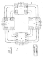
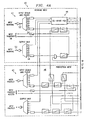
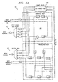
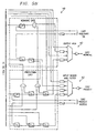
- FIGUREs 4-7 illustrate an optical BLSR system to satisfy the requirements identified in the previous section.
- the design is intended to transport N wavelengths of signals where N is at least two.
- the design is broken down into three major sections.
- the first section is a wave division multiplex/demultiplex section 42 that combines/splits the "line" signal into its individual wavelength components.
- the second section is a command and control channel 44 consisting of one wavelength on each fiber and an accompanying SONET standard BLSR ADM, which is illustrated in FIGURE 6 .
- the third section is a set of (N-1) slave circuits 46 as depicted in FIGURE 7 .
- Each slave circuits 46 can comprise from one to four slave channels in the embodiments shown.
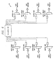
- the wave division multiplex/demultiplex section 42 includes four copies of the multiplex function (labeled OUTPUT MUX in FIGURE 4 ), and four copies of the demultiplex function (labeled INPUT DEMUX AND FILTER in FIGURE 4 ).
- This multiplexer function receives the individual wavelengths on separate input fibers 48 generated by the other sections, adjusts them if necessary for compatibility with the optical amplifiers and repeaters used elsewhere in the ring, and multiplexes them into the singe fiber output signal 50.
- the corresponding demultiplex function splits the incoming combined signal 52 into N individual wavelengths on separate output fibers 54 into the other sections, again adjusting them if necessary for compatibility.
- the command and control section 44 provides the "line” monitoring, switching signaling, and overall control of the optical BLSR ADAM 40. It also carries 1/Nth of the traffic of the system via the electrical SONET ADM's tributaries 56 and high speed optical lines. To provide the "line” monitoring of the overall optical ADM, the SONET ADM uses its own generated line signals with their inherit BIP--8 line parity checking. Any degradation or cut in the combined fiber signal can reasonably be assumed to affect all carried wavelengths on that fiber equally. Thus any "line” fault will be detected by the SONET ADM 40 and, in its normal course of actions, protected by its BLSR switching protocol and hardware.
- the protocol it uses is embedded in the standard SONET overhead bytes (K1/K2 in SONET terminology) carried in the SONET ADM's high speed overhead channels. These same overhead channels (bytes D1-D12 and E1/E2 in SONET terminology) also provide the optical ADM's maintenance channels for maintenance data traffic and maintenance voice communications.
- the design provides the requirements for items (1), (3) and (4) while meeting the needs imposed by item (5). It also provides item (2) requirements for the one set of payloads carried by the SONET ADM itself. Note that the SONET ADM actually only directly protects its own high speed wavelength signal by performing ring or span switches upon its high speed fibers.
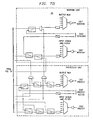
- each of the (N-1) slave circuits 46 has the optical hardware necessary to perform a ring or span switch of its own signal, see FIGURE 7 .
- the use of this hardware is slaved to control information provided by the SONET BLSR ADM an the command and control section 44.
- the slave sections perform the equivalent physical function for their individual wavelengths.
- the providing of this control information, as well as the related squelching information, is the modification required of the SONET ADM used for command and control.
- the slave sections also provide, as shown in FIGURE 7 , the switching for adding and dropping optical signals at their respective wavelengths.
- an optical BLSR network includes a plurality of optical BLSR rings, wherein at least one of the optical BLSR rings is an optical BLSR ring as described with reference to FIGUREs 4-7 above.
- FIGURE 8 illustrates an embodiment allowing for such data transmission.
- the system of FIGURE 8 which may be referred to as a dual-node interconnnected ring system 60 , allows data to be transmitted from the first ring 62 to the second ring 64 with a high degree of fault protection. Data is transmitted from a first ADM 66 on the first ring to a first ADM 68 on the second ring, and the same data is transmitted from the second ADM 70 on the first ring to the second ADM 72 on the second rang. By transferring the data at two separate nodes, redundancy is established such that if there is a problem with either ring or with one of the nodes, an alternate path exists for the data. Connecting to each input multiplexer is a monitor that permits looking for loss of signal defected signals.
Landscapes
- Engineering & Computer Science (AREA)
- Computer Networks & Wireless Communication (AREA)
- Signal Processing (AREA)
- Optical Communication System (AREA)
- Small-Scale Networks (AREA)
- Use Of Switch Circuits For Exchanges And Methods Of Control Of Multiplex Exchanges (AREA)
- Cable Transmission Systems, Equalization Of Radio And Reduction Of Echo (AREA)
- Communication Control (AREA)
Claims (37)
- Anneau (10) commuté de lignes optiques bidirectionnelles à fibres multiples conçu pour transporter N longueurs d'onde de signaux, N étant au moins égal à 2, comprenant une pluralité de noeuds multiplexeurs à insertion/extraction optiques (20) connectés les uns aux autres par de multiples fibres (50, 52), chaque noeud multiplexeur à insertion/extraction optique comprenantde multiples sections (42) de démultiplexeur d'entrée / multiplexeur de sortie, chaque section comprenant un démultiplexeur d'entrée et un multiplexeur de sortie connecté à l'une des multiples fibres (50, 52);jusqu'à N-1 circuits esclaves (46), chaque circuit esclave comprenant une pluralité de circuits de commutation optiques connectés aux multiples sections (42) de démultiplexeur d'entrée /multiplexeur de sortie de telle sorte que les circuits de commutation optiques puissent être utilisés pour transporter jusqu'à N longueurs d'onde de trafic, etune section de commande et de contrôle (44) comprenant une longueur d'onde de surveillance sur chaque fibre des multiples fibres (50, 52), ladite section de commande et de contrôle étant connectée a chacune des sections de multiplexeur d'entrée / démultiplexeur de sortie ;caractérisé en ce que la section de commande et de contrôle (44) est conçue pour surveiller les signaux auxdites longueurs d'onde sur les multiples fibres et pour contrôler le fonctionnement de la pluralité de circuits de commutation optiques desdits N-1 circuits esclaves (46) en réaction aux signaux détectés sur lesdites longueurs d'onde
- Système selon la revendication 1, l'anneau (10) commuté de lignes optiques bidirectionnelles à fibres multiples étant un anneau commuté de lignes optiques bidirectionnelles à quatre fibres comprenant deux canaux utiles et deux canaux de protection, et les multiples sections (42) de démultiplexeur d'entrée / multiplexeur de sortie comprenant quatre sections de démultiplexeur d'entrée / multiplexeur de sortie et la section de commande et de contrôle (44) comprenant quatre fibres, et chacun des démultiplexeurs d'entrée recevant soit un canal utile, soit un canal de protection sur l'une des quatre fibres
- Système selon la revendication 1, la pluralité de noeuds multiplexeurs à insertion/extraction optiques (20) contenant de deux à seize noeuds multiplexeurs à insertion/extraction optiques
- Système selon la revendication 1, les N-1 circuits esclaves (46) comprenant chacun deux affluents (56) pour réaliser jusqu'à 2N-2 longueurs d'onde optiques de trafic utile entièrement protégé
- Système selon la revendication 4, chaque affluent (56) résidant dans l'une des N longueurs d'onde
- Système selon la revendication 1, les N-1 circuits esclaves (46) comprenant chacun deux affluents (56) pour réaliser jusqu'à 4N-4 longueurs d'onde optiques d'affluents de trafic insérées/extraites au niveau de chaque noeud (20), 2N-2 longueurs d'onde du trafic étant un trafic utile entièrement protégé
- Système selon la revendication 1, chacun des N-1 circuits esclaves (46) comprenant en plus jusqu'à quatre canaux esclaves et au moins l'un des canaux esclaves étant un canal de protection pour le circuit esclave
- Système selon la revendication 1, la section de commande et de contrôle (44) étant un multiplexeur à insertion/extraction électrique à anneau bidirectionnel à fibres multiples
- Système selon la revendication 1, chaque démultiplexeur d'entrée recevant un signal d'entrée de la part d'un autre noeud et démultiplexant ce signal d'entrée en N longueurs d'onde, N représentant la capacité de multiplexage de chaque démultiplexeur d'entrée dans un noeud particulier (20) et chaque multiplexeur de sortie recevant les N longueurs d'onde provenant de l'intérieur du noeud (20) et multiplexant les N longueurs d'onde en un signal de sortie
- Système selon la revendication 9, chacun des N-1 circuits esclaves (46) comprenant en plus jusqu'à 4 canaux esclaves et chaque canal esclave pouvant être utilisé pour transporter une longueur d'onde du signal d'entré démultiplexé à N longueurs d'onde s'il se produit une défaillance qui nécessite la protection de ce signal d'entrée
- Système selon la revendication 1, comprenant en plusun deuxième anneau commuté de lignes optiques bidirectionnelles à fibres multiples (64), et une section d'extraction et de poursuite connectant le premier anneau commuté de lignes optiques bidirectionnelles à fibres multiples (62) au deuxième anneau commuté de lignes optiques bidirectionnelles à fibres multiples (64), la section d'extraction et de poursuite étant conçue pour transmettre des données d'un premier multiplexeur à insertion/extraction (68) sur le premier anneau (62) vers un premier multiplexeur à insertion/extraction (68) sur le deuxième anneau (64)
- Système selon la revendication 11, la section d'extraction et de poursuite étant en plus utilisée pour transmettre des données d'un deuxième multiplexeur à insertion/extraction (70) sur le premier anneau (62) vers un deuxième multiplexeur à insertion/extraction (72) sur le deuxième anneau (64)
- Système selon la revendication 2, la section de commande et de contrôle (44) étant conçue pour générer un signal sur chacune de ses multiples fibres, lequel est transporté sur chacune des multiples fibres de l'anneau (10) commuté de lignes optiques bidirectionnelles à fibres multiples de manière à surveiller efficacement la qualité de chaque signal sur les fibres multiples en surveillant la qualité de son signal de commande et de contrôle
- Système selon la revendication 13, la section de commande et de contrôle (44) étant conçue pour, sur détection d'un défaut dans son signal de commande et de contrôle, initier une commutation pour commuter le trafic d'un premier chemin vers un deuxième chemin dans le système
- Système selon la revendication 14, le commutateur faisant en plus appel à la section de commande et de contrôle (44) pour initier une commutation du signal qui circule à travers la section de commande et de contrôle (44) vers un nouveau chemin et les N 1 circuits esclaves (48) exécutant une commutation correspondante de sorte que le trafic restant soit lui aussi commuté vers le nouveau chemin
- Système selon la revendication 15, la section de commande et de contrôle (44) étant en communication avec chaque noeud (20) au sein du système pour négocier un commutateur de protection
- Système selon la revendication 1, l'anneau (10) commuté de lignes optiques bidirectionnelles à fibres multiples étant un anneau commuté de lignes optiques bidirectionnelles à deux fibres, et les multiples sections (42) de démultiplexeur d'entrée /multiplexeur de sortie comprenant deux sections de démultiplexeur d'entrée / multiplexeur de sortie et chacun des démultiplexeurs d'entrée recevant en plus soit un canal utile, soit un canal de protection sur l'une des deux fibres
- Noeud multiplexeur à insertion/extraction optique destiné à être utilisé dans un anneau (10 commuté de lignes optiques bidirectionnelles à fibres multiples conçu pour transporter N longueurs d'onde de signaux optiques, N étant au moins égal à 2, comprenantde multiples sections (42) de démultiplexeur d'entrée / multiplexeur de sortie, chaque section comprenant un démultiplexeur d'entrée et un multiplexeur de sortie connecté à l'une des multiples fibres (50, 52),jusqu'à N-1 circuits esclaves (46), chaque circuit esclave comprenant une pluralité de circuits de commutation optiques connectés aux multiples sections (42) de démultiplexeur d'entrée /multiplexeur de sortie de telle sorte que les circuit de commutation optiques puissent être utilisés pour transporter jusqu'à N longueurs d'onde de trafic, etune section de commande et de contrôle (44) comprenant une longueur d'onde de surveillance sur chaque fibre des multiples fibres (50, 52), ladite section de commande et de contrôle étant connectée à chacune des sections de multiplexeur d'entrée / démultiplexeur de sortie;caracténsé en ce que la section de commande et de contrôle (44) est conçue pour surveiller les signaux auxdites longueurs d'onde des multiples fibres et pour contrôler le fonctionnement de la pluralité de circuits de commutation optiques desdits N-1 circuits esclaves (48) en réaction aux signaux détectés sur lesdites longueurs d'onde
- Noeud multiplexeur selon la revendication 18, les multiples sections (42) de démultiplexeur d'entrée / multiplexeur de sortie comprenant quatre sections de démultiplexeur d'entrée / multiplexeur de sortie et la section de commande et de contrôle (44) comprenant quatre fibres, et chacun des démultiplexeurs d'entrée recevant en plus soit un canal utile, soit un canal de protection sur l'une des quatre fibres
- Noeud multiplexeur selon la revendication 18, les N-1 circuits esclaves (46) comprenant chacun deux affluents (56) pour réaliser jusqu'à 2N-2 longueurs d'onde optiques de trafic utile entièrement protégé
- Noeud multiplexeur selon la revendication 20, chaque affluent (56) résidant dans l'une des N longueurs d'onde
- Noeud multiplexeur selon la revendication 18, les N-1 circuits esclaves (46) comprenant chacun deux affluents (56) pour réaliser Jusqu'à 4N-4 longueurs d'onde optiques d'affluents de trafic insérées/extraites au niveau de chaque noeud (20), 2N-2 longueurs d'onde du trafic étant un trafic utile entièrement protégé
- Noeud multiplexeur selon la revendication 18, chacun des N-1 circuits esclaves (46) comprenant en plus jusqu'à 4 canaux esclaves et au moins l'un des canaux esclaves étant un canal de protection pour chaque N-1 circuit esclave (46)
- Noeud multiplexeur selon la revendication 18 la section de commande et de contrôle (44) étant un commutateur électrique bidirectionnel à fibres multiples
- Noeud multiplexeur selon la revendication 18, chaque démultiplexeur d'entrée recevant un signal d'entrée de la part d'un autre noeud (20) et démultiplexant ce signal d'entrée en N longueurs d'onde, N représentant la capacité de multiplexage de chaque démultiplexeur d'entrée dans un noeud particulier et chaque multiplexeur de sortie recevant les N longueurs d'onde provenant de l'intérieur du noeud et multiplexant les N longueurs d'onde en un signal de sortie
- Noeud multiplexeur selon la revendication 25, chacun des N-1 circuits esclaves (46) comprenant en plus jusqu'à 4 canaux esclaves et chaque canal esclave pouvant être utilisé pour transporter une longueur d'onde du signal d'entrée démultiplexé à N longueurs d'onde s'il se produit une défaillance qui nécessite la protection de ce signal d'entrée
- Noeud multiplexeur selon la revendication 19, la section de commande et de contrôle (44) étant conçue pour générer et surveiller un signal sur chacune de ses multiples fibres et, sur détection d'un défaut dans l'un quelconque de ses signaux de commande et de contrôle, initier une commutation pour commuter le trafic d'un premier chemin vers un deuxième chemin dans le systeme
- Noeud multiplexeur selon la revendication 27, le commutateur faisant en plus appel à la section de commande et de contrôle (44) pour initier une commutation du signal qui circule à travers la section de commande et de contrôle (44) vers un nouveau chemin et les N-1 circuits esclaves (48) exécutant une commutation correspondante de sorte que le trafic restant soit lui aussi commuté vers le nouveau chemin
- Procédé pour réaliser la protection du trafic circulant dans un anneau (10) commuté de lignes optiques bidirectionnelles à fibres multiples conçu pour transporter N longueurs d'onde de signaux, N étant au moins égal à 2 et l'anneau commuté de lignes optiques bidirectionnelles à fibres multiples comprenant une pluralité de noeuds multiplexeurs à insertion/extraction optiques (20), chaque noeud multiplexeur à insertion/extraction optique comprenant de multiples sections (42) de démultiplexeur d'entrée / multiplexeur de sortie, chaque section comprenant un démultiplexeur d'entrée et un multiplexeur de sortie connecté à l'une des multiples fibres (50, 52), une section de commande et de contrôle (44) comprenant une longueur d'onde de surveillance sur chaque fibre des multiples fibres (50, 52), ladite section de commande et de contrôle étant connectée à chacune des sections de multiplexeur d'entrée / démultiplexeur de sortie, et Jusqu'à N 1 circuit esclaves (46), chaque circuit esclave comprenant une pluralité de circuits de commutation optiques connectés aux multiples sections (42) de démultiplexeur d'entrée / multiplexeur de sortie de telle sorte que les circuits de commutation optiques puissent être utilisés pour transporter jusqu'à N longueurs d'onde de trafic, le procédé comprenantréception d'un signal sur chacun des démultiplexeurs d'entrée , démultiplexage du signal en N longueurs d'onde ,envoi de ladite longueur d'onde de surveillance à la section de commande et de contrôle (44),envoi des N-1 longueurs d'onde restantes aux N-1 circuits esclaves (46),caractérisé par la surveillance de la qualité du signal à la longueur d'onde de commande et de contrôle; et le contrôle du fonctionnement de la pluralité de circuits de commutation optiques desdits N-1 circuits esclaves (46) en réaction à la qualité de signal détectée à la longueur d'onde de commande et de contrôle
- Procédé selon la revendication 29, comprenant en plus
sur détection d'un défaut dans le signal de commande et de contrôle, initiation d'une commutation pour commuter le trafic d'un premier chemin vers un deuxième chemin dans le système - Procédé selon la revendication 30, l'initiation d'une commutation comprenant en plus l'initiation d'une commutation pour la longueur d'onde de commande et de contrôle par la section de commande et de contrôle (44) et l'initiation d'une commutation pour les N-1 longueurs d'onde par les N-1 circuits esclaves (46), chacun de ceux-ci commutant les N longueurs d'onde vers un chemin correspondant
- Procédé selon la revendication 29, l'anneau (10) commuté de lignes optiques bidirectionnelles à fibres multiples étant un anneau commuté de lignes optiques bidirectionnelles à quatre fibres comprenant deux canaux utiles et deux canaux de protection, et les multiples sections (42) de démultiplexeur d'entrée / multiplexeur de sorte comprenant quatre sections de démultiplexeur d'entrée / multiplexeur de sortie et la section de commande et de contrôle (44) comprenant quatre fibres, et chacun des démultiplexeurs d'entrée recevant soit un canal utile, soit un canal de protection sur l'une des quatre fibres
- Procédé selon la revendication 29, les N-1 circuits esclaves (46) comprenant chacun deux affluents (56) pour réaliser jusqu'à 4N-4 longueurs d'onde optiques d'affluents de trafic insérées/extraites au niveau de chaque noeud, 2N-2 longueurs d'onde du trafic étant un trafic utile entièrement protégé et chaque affluent résidant dans l'une des N longueurs d'onde
- Procédé selon la revendication 29, chacun des N-1 circuits esclaves (46) comprenant en plus jusqu'à 4 canaux esclaves et le procédé comprenant en plus réalisation de la protection de chacun des N-1 circuits esclaves (46) par le biais d'au moins l'un des canaux esclaves dans chacun des N-1 circuits esclaves (46)
- Procédé selon la revendication 29, comprenant en plusconnexion d'un deuxième anneau commuté de lignes optiques bidirectionnelles à fibres multiples (64) au premier anneau commuté de lignes optiques bidirectionnelles à fibres multiples (62) , etconnexion d'une section d'extraction et de poursuite entre le premier anneau commuté de lignes optiques bidirectionnelles à fibres multiples (62) et le deuxième anneau commuté de lignes optiques bidirectionnelles à fibres multiples (64);et transmission de données par le biais de la section d'extraction et de poursuite d'un premier multiplexeur à insertion/extraction (66) sur le premier anneau (62) vers un premier multiplexeur à insertion/extraction (66) sur le deuxième anneau (64)
- Procédé selon la revendication 35, comprenant en plus
transmission de données par le biais de la section d'extraction et de poursuite d'un deuxième multiplexeur à insertion/extraction (70) sur le premier anneau (62) vers un deuxième multiplexeur à insertion/extraction (72) sur le deuxième anneau (64) - Procédé selon la revendication 29, l'anneau (10) commuté de lignes optiques bidirectionnelles à fibres multiples étant un anneau (10) commuté de lignes optiques bidirectionnelles à deux fibres ayant deux canaux utiles et deux canaux de protection, et les multiples sections (42) de démultiplexeur d'entrée / multiplexeur de sortie comprenant deux sections de démultiplexeur d'entrée / multiplexeur de sortie et chacun des démultiplexeurs d'entrée recevant en plus soit un canal utile, soit un canal de protection sur l'une des deux fibres
Applications Claiming Priority (3)
| Application Number | Priority Date | Filing Date | Title |
|---|---|---|---|
| US4332297P | 1997-04-15 | 1997-04-15 | |
| US43322P | 1997-04-15 | ||
| PCT/US1998/007539 WO1998047255A1 (fr) | 1997-04-15 | 1998-04-14 | Procede et appareil pour un systeme de communication de donnees a anneau optique bidirectionnel a commutation de lignes |
Publications (2)
| Publication Number | Publication Date |
|---|---|
| EP0976215A1 EP0976215A1 (fr) | 2000-02-02 |
| EP0976215B1 true EP0976215B1 (fr) | 2009-06-03 |
Family
ID=21926575
Family Applications (1)
| Application Number | Title | Priority Date | Filing Date |
|---|---|---|---|
| EP98918217A Expired - Lifetime EP0976215B1 (fr) | 1997-04-15 | 1998-04-14 | Procede et appareil pour un systeme de communication de donnees a anneau optique bidirectionnel a commutation de lignes |
Country Status (7)
| Country | Link |
|---|---|
| US (1) | US6163527A (fr) |
| EP (1) | EP0976215B1 (fr) |
| JP (1) | JP4070246B2 (fr) |
| AT (1) | ATE433234T1 (fr) |
| CA (1) | CA2286593A1 (fr) |
| DE (1) | DE69840867D1 (fr) |
| WO (1) | WO1998047255A1 (fr) |
Families Citing this family (57)
| Publication number | Priority date | Publication date | Assignee | Title |
|---|---|---|---|---|
| US6657952B1 (en) | 1997-11-28 | 2003-12-02 | Nec Corporation | Ring network for sharing protection resource by working communication paths |
| JPH11239100A (ja) * | 1998-02-20 | 1999-08-31 | Fujitsu Ltd | 冗長構成を有する光波長多重システム |
| EP0986226B1 (fr) * | 1998-09-11 | 2007-01-17 | Hitachi, Ltd. | Appareil de communication par paquets IP |
| JP3531526B2 (ja) * | 1999-05-13 | 2004-05-31 | 日本電気株式会社 | 通信システム |
| JP3586586B2 (ja) * | 1999-05-24 | 2004-11-10 | 日本電気株式会社 | 光波リングシステム |
| US6381643B1 (en) * | 1999-11-08 | 2002-04-30 | International Business Machines Corporation | Mechanism and procedure for detecting switch mis-cabling |
| JP3584965B2 (ja) * | 1999-12-09 | 2004-11-04 | 日本電気株式会社 | 光ラインプロテクション方式 |
| WO2001067136A2 (fr) * | 2000-03-03 | 2001-09-13 | Corning, Inc. | Architecture d'interconnexion d'un anneau |
| US6922530B1 (en) * | 2000-04-06 | 2005-07-26 | Fujitsu Limited | Method and apparatus for optical channel switching in an optical add/drop multiplexer |
| US6795394B1 (en) * | 2000-04-26 | 2004-09-21 | Nortel Networks Limited | Data network having enhanced availability of extra traffic |
| FR2809905B1 (fr) * | 2000-05-30 | 2002-08-30 | Cit Alcatel | Procede de transfert avec traitement de signaux entre deux interfaces d'emission/reception distinctes |
| JP2001352342A (ja) * | 2000-06-07 | 2001-12-21 | Fujitsu Ltd | ネットワーク管理方法及びネットワークノード装置並びにメッシュ型ネットワーク |
| US6865148B1 (en) * | 2000-09-15 | 2005-03-08 | Ciena Corporation | Method for routing network switching information |
| JP4592170B2 (ja) * | 2000-10-18 | 2010-12-01 | 株式会社東芝 | 光伝送装置 |
| WO2002054633A1 (fr) * | 2000-12-30 | 2002-07-11 | Redback Networks Inc. | Provisionnement d'une voie a couche 2/3 protegee par un anneau a protection de section non bidirectionnel |
| US7209436B1 (en) * | 2000-12-30 | 2007-04-24 | Redback Networks Inc. | Method and apparatus for variable rate pipes |
| US7016300B2 (en) * | 2000-12-30 | 2006-03-21 | Redback Networks Inc. | Protection mechanism for an optical ring |
| US6975589B2 (en) * | 2000-12-30 | 2005-12-13 | Redback Networks Inc. | Method and apparatus for a hybrid variable rate pipe |
| US6577412B2 (en) | 2001-02-02 | 2003-06-10 | Fujitsu Network Communications, Inc. | System and method of determining end point candidates for an optical channel in a data network |
| US7110364B1 (en) | 2001-04-19 | 2006-09-19 | Fujitsu Limited | Optical link adjacency discovery protocol and an optical network therefor |
| US6307986B1 (en) | 2001-04-24 | 2001-10-23 | Seneca Networks | Protection switching in bidirectional WDM optical communication networks with transponders |
| US6321004B1 (en) | 2001-04-24 | 2001-11-20 | Seneca Networks | Protection switching in bidirectional WDM optical communication networks |
| US7272307B2 (en) * | 2001-05-25 | 2007-09-18 | Tellabs Operations, Inc. | Virtual protection channel for fiber optic ring network |
| US7643492B2 (en) | 2001-05-30 | 2010-01-05 | Fujitsu Limited | Network bandwidth reservation method |
| US6594234B1 (en) | 2001-05-31 | 2003-07-15 | Fujitsu Network Communications, Inc. | System and method for scheduling traffic for different classes of service |
| US8385342B2 (en) | 2001-05-31 | 2013-02-26 | Fujitsu Limited | System and method of virtual private network route target filtering |
| US8228797B1 (en) | 2001-05-31 | 2012-07-24 | Fujitsu Limited | System and method for providing optimum bandwidth utilization |
| US7450505B2 (en) * | 2001-06-01 | 2008-11-11 | Fujitsu Limited | System and method for topology constrained routing policy provisioning |
| US20020184388A1 (en) * | 2001-06-01 | 2002-12-05 | Nimer Yaseen | Layered approach to virtual private routing |
| US7289429B2 (en) * | 2001-06-01 | 2007-10-30 | Fujitsu Network Communications, Inc. | System and method to perform non-service effecting bandwidth reservation using a reservation signaling protocol |
| US7245635B2 (en) * | 2001-06-01 | 2007-07-17 | Fujitsu Limited | System and method for resizing the physical link bandwidth based on utilization thereof |
| US8014283B2 (en) * | 2001-06-01 | 2011-09-06 | Fujitsu Limited | System and method for topology constrained QoS provisioning |
| US7756957B2 (en) | 2001-06-01 | 2010-07-13 | Fujitsu Limited | End-to-end governed data transfers in a network |
| US7450578B2 (en) * | 2001-06-01 | 2008-11-11 | Fujitsu Limited | Method of addressing and routing data |
| US7912074B2 (en) * | 2001-06-01 | 2011-03-22 | Fujitsu Limited | System and method of multiplexing data from multiple ports |
| US6834056B2 (en) | 2001-06-26 | 2004-12-21 | Occam Networks | Virtual local area network protection switching |
| US20030005165A1 (en) * | 2001-06-28 | 2003-01-02 | Dave Langridge | Protection switching in ring-configured networks |
| US6766482B1 (en) * | 2001-10-31 | 2004-07-20 | Extreme Networks | Ethernet automatic protection switching |
| US7382789B2 (en) * | 2002-02-06 | 2008-06-03 | Wuhan Fiberhome Networks Co. Ltd. | Resilient multiple service ring |
| US7116905B2 (en) | 2002-03-27 | 2006-10-03 | Fujitsu Limited | Method and system for control signaling in an open ring optical network |
| US7231148B2 (en) * | 2002-03-28 | 2007-06-12 | Fujitsu Limited | Flexible open ring optical network and method |
| US7206281B2 (en) * | 2002-05-03 | 2007-04-17 | Ciena Corporation | Calculating physical routes in a communication network |
| US8463947B2 (en) * | 2002-08-28 | 2013-06-11 | Tellabs Operations, Inc. | Method of finding rings for optimal routing of digital information |
| US7346709B2 (en) * | 2002-08-28 | 2008-03-18 | Tellabs Operations, Inc. | Methods for assigning rings in a network |
| US20040052530A1 (en) * | 2002-09-17 | 2004-03-18 | Cechan Tian | Optical network with distributed sub-band rejections |
| WO2004043011A1 (fr) * | 2002-11-06 | 2004-05-21 | Wuhan Fiberhome Networks Co., Ltd. | Anneau multiservices de structure a n boucles base sur plusieurs fe, ge et 10ge |
| US7421197B2 (en) * | 2003-01-21 | 2008-09-02 | Fujitsu Limited | Optical network protection switching architecture |
| US7509438B1 (en) | 2003-02-14 | 2009-03-24 | Cisco Technology, Inc. | Bi-directional line switched ring support for path trace monitoring on a protection path |
| US7483636B2 (en) | 2003-07-28 | 2009-01-27 | Fujitsu Limited | Optical network with sub-band rejection and bypass |
| US7023793B2 (en) * | 2003-08-01 | 2006-04-04 | Ciena Corporation | Resiliency of control channels in a communications network |
| JP4001093B2 (ja) * | 2003-09-18 | 2007-10-31 | オムロン株式会社 | プログラマブルコントローラおよび二重化ネットワークシステム |
| US20050095001A1 (en) * | 2003-10-29 | 2005-05-05 | Fujitsu Limited | Method and system for increasing network capacity in an optical network |
| US7450851B2 (en) * | 2004-08-27 | 2008-11-11 | Fujitsu Limited | System and method for modularly scalable architecture for optical networks |
| CN101321031B (zh) * | 2008-07-16 | 2011-12-07 | 中兴通讯股份有限公司 | 一种波分复用环网中的共享保护方法及系统 |
| DE102009023485A1 (de) * | 2009-06-02 | 2010-12-09 | T-Mobile International Ag | Verfahren zur Übertragung von Echtzeit-Datenpaketen in konvergenten Netzen |
| CN102142975B (zh) * | 2010-02-01 | 2015-05-13 | 中兴通讯股份有限公司 | 基于传送网中双节点互连保护结构的业务保护方法及系统 |
| US12225333B2 (en) * | 2020-09-11 | 2025-02-11 | Nippon Telegraph And Telephone Corporation | Optical communication system, monitoring device, and monitoring method |
Family Cites Families (5)
| Publication number | Priority date | Publication date | Assignee | Title |
|---|---|---|---|---|
| EP0651528B1 (fr) * | 1993-10-29 | 2003-01-22 | Siemens Aktiengesellschaft | Réseau optique transparent en anneau avec voies de réserve |
| JPH0818592A (ja) * | 1994-06-30 | 1996-01-19 | Fujitsu Ltd | 光学的スイッチングによるリング保護を有する光ファイバー伝送システム |
| IT1277204B1 (it) * | 1995-10-19 | 1997-11-05 | Pirelli S P A Ora Pirelli Cavi | Rete di comunicazione ottica trasparente ad anello autoprotetto |
| JP3640721B2 (ja) * | 1996-02-05 | 2005-04-20 | 富士通株式会社 | リング伝送システムの異方式移行方法および伝送装置 |
| US5751454A (en) * | 1996-10-10 | 1998-05-12 | Northern Telecom Limited | Wavelength bypassed ring networks |
-
1998
- 1998-04-14 JP JP54423898A patent/JP4070246B2/ja not_active Expired - Lifetime
- 1998-04-14 WO PCT/US1998/007539 patent/WO1998047255A1/fr not_active Ceased
- 1998-04-14 AT AT98918217T patent/ATE433234T1/de not_active IP Right Cessation
- 1998-04-14 US US09/059,919 patent/US6163527A/en not_active Expired - Lifetime
- 1998-04-14 EP EP98918217A patent/EP0976215B1/fr not_active Expired - Lifetime
- 1998-04-14 DE DE69840867T patent/DE69840867D1/de not_active Expired - Lifetime
- 1998-04-14 CA CA002286593A patent/CA2286593A1/fr not_active Abandoned
Also Published As
| Publication number | Publication date |
|---|---|
| EP0976215A1 (fr) | 2000-02-02 |
| JP4070246B2 (ja) | 2008-04-02 |
| DE69840867D1 (de) | 2009-07-16 |
| WO1998047255A1 (fr) | 1998-10-22 |
| ATE433234T1 (de) | 2009-06-15 |
| CA2286593A1 (fr) | 1998-10-22 |
| JP2001520830A (ja) | 2001-10-30 |
| US6163527A (en) | 2000-12-19 |
Similar Documents
| Publication | Publication Date | Title |
|---|---|---|
| EP0976215B1 (fr) | Procede et appareil pour un systeme de communication de donnees a anneau optique bidirectionnel a commutation de lignes | |
| JP3008260B2 (ja) | 光伝送路のリングネットワーク通信構造とその構造用の再構成可能ノード | |
| EP0548648B1 (fr) | Dispositif de protection en forme d'anneau 1:N | |
| US6701085B1 (en) | Method and apparatus for data transmission in the wavelength-division multiplex method in an optical ring network | |
| EP0848873B1 (fr) | Systeme de telecommunication optique | |
| US6046833A (en) | Method and apparatus for operation, protection, and restoration of heterogeneous optical communication networks | |
| US5986783A (en) | Method and apparatus for operation, protection, and restoration of heterogeneous optical communication networks | |
| US7072580B2 (en) | Autoprotected optical communication ring network | |
| US6205158B1 (en) | Network architectures with transparent transport capabilities | |
| JPH0637781A (ja) | リング・ノードと通信回路転送方法 | |
| US6579018B1 (en) | Four-fiber ring optical cross connect system using 4×4 switch matrices | |
| EP0949777A2 (fr) | Protection de chemin commutée et partagée | |
| US6973267B1 (en) | Autoprotected optical communication ring network | |
| JP2006166037A (ja) | 光伝送装置および光伝送システム | |
| US8861956B2 (en) | Apparatus and method for switching paths in a wavelength-multiplexing network | |
| US7302180B2 (en) | Dual homing for DWDM networks in fiber rings | |
| EP0931392B1 (fr) | Appareil et procede permettant de retablir les connexions dans des reseaux de communication a fibre optique | |
| EP1075105B1 (fr) | Réseau de communication en forme d'anneau auto-protégé | |
| US7519293B1 (en) | Optical communication system having ring-based restoration using shared protect links | |
| EP1065822A1 (fr) | Réseau de communication optique en forme d'anneau auto-protégé | |
| CA2261448C (fr) | Architectures reseau avec fonctions de transport transparentes | |
| JP2002540700A (ja) | ネットワークにおける障害保護 | |
| JPH11112422A (ja) | 波長多重網切替え装置及び波長多重リング光ネットワーク・システム | |
| CA1279132C (fr) | Systeme de transmission en anneau | |
| CA2295407A1 (fr) | Protection optique simplifiee |
Legal Events
| Date | Code | Title | Description |
|---|---|---|---|
| PUAI | Public reference made under article 153(3) epc to a published international application that has entered the european phase |
Free format text: ORIGINAL CODE: 0009012 |
|
| 17P | Request for examination filed |
Effective date: 19991111 |
|
| AK | Designated contracting states |
Kind code of ref document: A1 Designated state(s): AT BE CH CY DE DK ES FI FR GB GR IE IT LI LU MC NL PT SE |
|
| RIN1 | Information on inventor provided before grant (corrected) |
Inventor name: DEMPSEY, DONALD, G. Inventor name: ESTER, GARY, W. |
|
| 17Q | First examination report despatched |
Effective date: 20031002 |
|
| GRAP | Despatch of communication of intention to grant a patent |
Free format text: ORIGINAL CODE: EPIDOSNIGR1 |
|
| GRAS | Grant fee paid |
Free format text: ORIGINAL CODE: EPIDOSNIGR3 |
|
| GRAA | (expected) grant |
Free format text: ORIGINAL CODE: 0009210 |
|
| RAP1 | Party data changed (applicant data changed or rights of an application transferred) |
Owner name: ALCATEL-LUCENT USA INC. |
|
| AK | Designated contracting states |
Kind code of ref document: B1 Designated state(s): AT BE CH CY DE DK ES FI FR GB GR IE IT LI LU MC NL PT SE |
|
| REG | Reference to a national code |
Ref country code: GB Ref legal event code: FG4D |
|
| REG | Reference to a national code |
Ref country code: CH Ref legal event code: EP |
|
| REG | Reference to a national code |
Ref country code: IE Ref legal event code: FG4D |
|
| REF | Corresponds to: |
Ref document number: 69840867 Country of ref document: DE Date of ref document: 20090716 Kind code of ref document: P |
|
| PG25 | Lapsed in a contracting state [announced via postgrant information from national office to epo] |
Ref country code: FI Free format text: LAPSE BECAUSE OF FAILURE TO SUBMIT A TRANSLATION OF THE DESCRIPTION OR TO PAY THE FEE WITHIN THE PRESCRIBED TIME-LIMIT Effective date: 20090603 Ref country code: AT Free format text: LAPSE BECAUSE OF FAILURE TO SUBMIT A TRANSLATION OF THE DESCRIPTION OR TO PAY THE FEE WITHIN THE PRESCRIBED TIME-LIMIT Effective date: 20090603 |
|
| NLV1 | Nl: lapsed or annulled due to failure to fulfill the requirements of art. 29p and 29m of the patents act | ||
| PG25 | Lapsed in a contracting state [announced via postgrant information from national office to epo] |
Ref country code: SE Free format text: LAPSE BECAUSE OF FAILURE TO SUBMIT A TRANSLATION OF THE DESCRIPTION OR TO PAY THE FEE WITHIN THE PRESCRIBED TIME-LIMIT Effective date: 20090903 Ref country code: NL Free format text: LAPSE BECAUSE OF FAILURE TO SUBMIT A TRANSLATION OF THE DESCRIPTION OR TO PAY THE FEE WITHIN THE PRESCRIBED TIME-LIMIT Effective date: 20090603 |
|
| PG25 | Lapsed in a contracting state [announced via postgrant information from national office to epo] |
Ref country code: ES Free format text: LAPSE BECAUSE OF FAILURE TO SUBMIT A TRANSLATION OF THE DESCRIPTION OR TO PAY THE FEE WITHIN THE PRESCRIBED TIME-LIMIT Effective date: 20090914 |
|
| PG25 | Lapsed in a contracting state [announced via postgrant information from national office to epo] |
Ref country code: BE Free format text: LAPSE BECAUSE OF FAILURE TO SUBMIT A TRANSLATION OF THE DESCRIPTION OR TO PAY THE FEE WITHIN THE PRESCRIBED TIME-LIMIT Effective date: 20090603 |
|
| PG25 | Lapsed in a contracting state [announced via postgrant information from national office to epo] |
Ref country code: PT Free format text: LAPSE BECAUSE OF FAILURE TO SUBMIT A TRANSLATION OF THE DESCRIPTION OR TO PAY THE FEE WITHIN THE PRESCRIBED TIME-LIMIT Effective date: 20091003 |
|
| PLBE | No opposition filed within time limit |
Free format text: ORIGINAL CODE: 0009261 |
|
| STAA | Information on the status of an ep patent application or granted ep patent |
Free format text: STATUS: NO OPPOSITION FILED WITHIN TIME LIMIT |
|
| PG25 | Lapsed in a contracting state [announced via postgrant information from national office to epo] |
Ref country code: DK Free format text: LAPSE BECAUSE OF FAILURE TO SUBMIT A TRANSLATION OF THE DESCRIPTION OR TO PAY THE FEE WITHIN THE PRESCRIBED TIME-LIMIT Effective date: 20090603 |
|
| 26N | No opposition filed |
Effective date: 20100304 |
|
| PG25 | Lapsed in a contracting state [announced via postgrant information from national office to epo] |
Ref country code: GR Free format text: LAPSE BECAUSE OF FAILURE TO SUBMIT A TRANSLATION OF THE DESCRIPTION OR TO PAY THE FEE WITHIN THE PRESCRIBED TIME-LIMIT Effective date: 20090904 |
|
| PG25 | Lapsed in a contracting state [announced via postgrant information from national office to epo] |
Ref country code: MC Free format text: LAPSE BECAUSE OF NON-PAYMENT OF DUE FEES Effective date: 20100430 |
|
| REG | Reference to a national code |
Ref country code: CH Ref legal event code: PL |
|
| PG25 | Lapsed in a contracting state [announced via postgrant information from national office to epo] |
Ref country code: IE Free format text: LAPSE BECAUSE OF NON-PAYMENT OF DUE FEES Effective date: 20100414 |
|
| PG25 | Lapsed in a contracting state [announced via postgrant information from national office to epo] |
Ref country code: LI Free format text: LAPSE BECAUSE OF NON-PAYMENT OF DUE FEES Effective date: 20100430 Ref country code: CH Free format text: LAPSE BECAUSE OF NON-PAYMENT OF DUE FEES Effective date: 20100430 |
|
| PG25 | Lapsed in a contracting state [announced via postgrant information from national office to epo] |
Ref country code: IT Free format text: LAPSE BECAUSE OF FAILURE TO SUBMIT A TRANSLATION OF THE DESCRIPTION OR TO PAY THE FEE WITHIN THE PRESCRIBED TIME-LIMIT Effective date: 20090603 |
|
| PG25 | Lapsed in a contracting state [announced via postgrant information from national office to epo] |
Ref country code: CY Free format text: LAPSE BECAUSE OF FAILURE TO SUBMIT A TRANSLATION OF THE DESCRIPTION OR TO PAY THE FEE WITHIN THE PRESCRIBED TIME-LIMIT Effective date: 20090603 |
|
| PG25 | Lapsed in a contracting state [announced via postgrant information from national office to epo] |
Ref country code: LU Free format text: LAPSE BECAUSE OF NON-PAYMENT OF DUE FEES Effective date: 20100414 |
|
| REG | Reference to a national code |
Ref country code: GB Ref legal event code: 732E Free format text: REGISTERED BETWEEN 20131024 AND 20131030 |
|
| REG | Reference to a national code |
Ref country code: FR Ref legal event code: GC Effective date: 20140715 |
|
| REG | Reference to a national code |
Ref country code: FR Ref legal event code: RG Effective date: 20141015 |
|
| REG | Reference to a national code |
Ref country code: FR Ref legal event code: PLFP Year of fee payment: 18 |
|
| REG | Reference to a national code |
Ref country code: FR Ref legal event code: PLFP Year of fee payment: 19 |
|
| PGFP | Annual fee paid to national office [announced via postgrant information from national office to epo] |
Ref country code: DE Payment date: 20160421 Year of fee payment: 19 Ref country code: GB Payment date: 20160421 Year of fee payment: 19 |
|
| PGFP | Annual fee paid to national office [announced via postgrant information from national office to epo] |
Ref country code: FR Payment date: 20160421 Year of fee payment: 19 |
|
| REG | Reference to a national code |
Ref country code: DE Ref legal event code: R119 Ref document number: 69840867 Country of ref document: DE |
|
| GBPC | Gb: european patent ceased through non-payment of renewal fee |
Effective date: 20170414 |
|
| REG | Reference to a national code |
Ref country code: FR Ref legal event code: ST Effective date: 20171229 |
|
| PG25 | Lapsed in a contracting state [announced via postgrant information from national office to epo] |
Ref country code: DE Free format text: LAPSE BECAUSE OF NON-PAYMENT OF DUE FEES Effective date: 20171103 Ref country code: FR Free format text: LAPSE BECAUSE OF NON-PAYMENT OF DUE FEES Effective date: 20170502 |
|
| PG25 | Lapsed in a contracting state [announced via postgrant information from national office to epo] |
Ref country code: GB Free format text: LAPSE BECAUSE OF NON-PAYMENT OF DUE FEES Effective date: 20170414 |