EP0976315A2 - Abstreifer für Früchte und Zinken-Abstreifer - Google Patents
Abstreifer für Früchte und Zinken-Abstreifer Download PDFInfo
- Publication number
- EP0976315A2 EP0976315A2 EP99305858A EP99305858A EP0976315A2 EP 0976315 A2 EP0976315 A2 EP 0976315A2 EP 99305858 A EP99305858 A EP 99305858A EP 99305858 A EP99305858 A EP 99305858A EP 0976315 A2 EP0976315 A2 EP 0976315A2
- Authority
- EP
- European Patent Office
- Prior art keywords
- teeth
- flanging
- stripper
- rotor according
- tooth
- Prior art date
- Legal status (The legal status is an assumption and is not a legal conclusion. Google has not performed a legal analysis and makes no representation as to the accuracy of the status listed.)
- Granted
Links
- 239000002184 metal Substances 0.000 claims abstract description 26
- 229910052751 metal Inorganic materials 0.000 claims abstract description 26
- 239000004033 plastic Substances 0.000 claims description 12
- 229920003023 plastic Polymers 0.000 claims description 12
- 230000007704 transition Effects 0.000 claims description 4
- 241000196324 Embryophyta Species 0.000 description 9
- 235000013339 cereals Nutrition 0.000 description 7
- 239000000463 material Substances 0.000 description 7
- 210000003739 neck Anatomy 0.000 description 5
- 238000005299 abrasion Methods 0.000 description 4
- 230000000694 effects Effects 0.000 description 3
- 238000005452 bending Methods 0.000 description 2
- 230000001419 dependent effect Effects 0.000 description 2
- 238000003306 harvesting Methods 0.000 description 2
- 238000004519 manufacturing process Methods 0.000 description 2
- 244000025254 Cannabis sativa Species 0.000 description 1
- 229910000639 Spring steel Inorganic materials 0.000 description 1
- 229910000831 Steel Inorganic materials 0.000 description 1
- 241000209140 Triticum Species 0.000 description 1
- 235000021307 Triticum Nutrition 0.000 description 1
- 210000001520 comb Anatomy 0.000 description 1
- 230000000295 complement effect Effects 0.000 description 1
- 239000012141 concentrate Substances 0.000 description 1
- 238000005336 cracking Methods 0.000 description 1
- 230000004048 modification Effects 0.000 description 1
- 238000012986 modification Methods 0.000 description 1
- 230000002093 peripheral effect Effects 0.000 description 1
- 230000002028 premature Effects 0.000 description 1
- 239000010959 steel Substances 0.000 description 1
- 239000012815 thermoplastic material Substances 0.000 description 1
Images

Classifications
-
- A—HUMAN NECESSITIES
- A01—AGRICULTURE; FORESTRY; ANIMAL HUSBANDRY; HUNTING; TRAPPING; FISHING
- A01D—HARVESTING; MOWING
- A01D41/00—Combines, i.e. harvesters or mowers combined with threshing devices
- A01D41/06—Combines with headers
Definitions
- This invention relates to crop strippers for harvesting crops from standing plants, and in particular to the rotors of such strippers used for detaching the crops from the plants, and to the toothing of the rotors which perform this function.
- Crop strippers are best known for stripping grain from the heads of cereal crops such as wheat, and feed from herbage crops such as grass, but they can also be arranged to harvest other grain or seed crops, or to strip other parts of plants, such as leaves, young shoots or blossom from the stems of crops.
- the rotor of a crop stripper has stripper teeth projecting from its periphery, arranged in a series of transversely extended rows or combs, each row usually being made up of a number of similar comb plates, butted end to end.
- the customary tooth profile comprises a radially outwardly tapering outer portion extending from a radially inner portion in which the spacing between adjacent teeth increases to form a bulbous root opening having a maximum width greater than the width of a radially outer neck of the opening at the junction with the tapering outer portions of the teeth.
- the rotor In the operation of the crop stripper, the rotor is driven as the machine advances through the standing crop, the lower periphery of the rotor turning in the direction of advance, and the plant stems are trapped in the spaces between the projecting teeth. As the stems are drawn through the teeth, the grain or other crop is stripped from the stems.
- the efficiency of operation is dependent, to some extent at least, on the ability of the stripper teeth to minimise the amount of unwanted material that is taken up in addition to the crop parts being harvested. For this reason, it has been customary to make the comb plates of a thermoplastic material, which causes little, if any, damage to the crop stems that will detach them.
- the comb plates are thick enough to be relatively stiff yet they have a sufficient degree of elasticity to avoid permanent deformation if a tooth strikes an obstacle. Because the plastics is a relatively easily abraded material, however, the teeth wear very rapidly in some crops and require frequent replacement.
- the comb plates can be stamped or cut from metal sheet and in one proposed form of metal toothing disclosed in WO86/01972, the tapering outer portion of each tooth extending from the neck of the inner portion is provided with radiused or folded edges or flanges. These are intended to give a scooping action if the edges are directed forwards, or to have a squeezing action on the crop passing between them if they are directed rearwards. Because the flanged edges increase the stiffness, the flexure of such teeth under load must be concentrated in the relatively short inner portions where the bulbous openings are formed. If the teeth strike an obstacle, the flexure of these portions may be so great as to deform them plastically. Alternatively, high levels of stress generated in the stiffened outer portions can cause buckling of the flanged edges and so permanently deform the outer portions.
- the toothing proposed in W096/04776 is made of a relatively thin spring grade steel to give the required degree of elasticity with ease of manufacture, and it will have significant flexibility despite the flanging of its edges.
- the resistance of the crop stems as the stripper teeth move can therefore cause excessive flexure, reducing the efficiency of operation and in order to control the flexure of the teeth it has also been proposed to provide them with a backing of shorter and thicker plastic teeth.
- These plastic teeth extend outwards beyond the necks of the metal tooth inner portions but terminate some distance from the tips of the outer tapered portions of the teeth, so they are shielded from abrasion.
- the metal toothing is susceptible to cracking, in particular at the transition between the inner and outer portions of a tooth, which can lead to premature failure by fracture. It is proposed in W096/04776 that the flanging can be interrupted at the angular transitions between the bulbous openings and the tapering teeth to reduce stress concentrations there, but there is a risk that this measure concentrates any flexure under load at that point and lowers the limit at which plastic deformation of the teeth will occur.
- metal toothing for a stripper rotor comprising a series of teeth disposed side by side, each tooth having an outwardly tapered outer portion extending from a radially inner root portion where the spacing between adjacent teeth increases to form a root opening having a maximum width greater than the width of the radially outer neck of the root opening at the junction with the tapering outer portions of the teeth, the teeth having flanging along each said outer portion spaced from said root portion and extending over not substantially more than 70% of the radial length of the tooth profile measured from the radially inner edge of the root opening.
- the flanging extends over not substantially more than 60% of said radial length of the teeth.
- such toothing can be given support from shorter backing toothing, which may be of plastics, extending from the roots of the main toothing to at least part way along the tapering outer portions of the metal toothing, preferably extending into said flanged outer region.
- the backing teeth can support the main teeth against bending loads in a manner which spreads the flexure of each main tooth over a greater part of its radial extent, so reducing peak stresses. Bending loads on the main teeth are reduced thereby and the flexure of the teeth can be better controlled by the support provided.
- Toothing arranged according to the invention is able to offer many of the advantages of the continuously flanged toothing proposed in W096/04776 while accommodating increased deflections under impact loading.
- toothing according to the invention is able to accommodate a greater degree of flexure without damage.
- metal comb plate for a stripper rotor comprising a series of teeth disposed side by side, each tooth having an outwardly tapered outer portion extending from a radially inner root portion where the spacing between adjacent teeth increases to form a root opening having a maximum width greater than the width of the minimum spacing between the teeth, flanging on the edges of said teeth spaced from the root opening, said flanging extending from the radially outer ends of the teeth over a radial length not substantially more than 70%, and preferably not substantially more than 60%, of the radial length of the tooth profile measured from the radially inner edge of the root openings.
- the stripper teeth according to the invention helps to ensure that easily detached crops can be gathered without removing a significant quantity of unwanted parts of the plants, in particular the stems, where there is a risk that the unwanted material that is detached will interfere with the gathering of the crop that is being collected if it constitutes too large a quantity that must subsequently be separated to be discarded.
- the teeth are then arranged so that they can be operated with the flanging directed forwards, the leading edges of the flanging can provide a more aggressive stripping action on the crop. It may be noted that even on metal toothing, wear will occur by abrasion and in this respect the forwardly directed flanging has the advantage of increasing the life of the toothing because an active forward-facing edge will be maintained while the flanging is worn away.
- the toothing is arranged so that it can be mounted on the rotor with the flanging directly forwards or rearwards to choice, the selection being made according to the particular crop being harvested.
- the flanging on the tapering outer portions of toothing according to the invention may extend over 10% to 90% of the radial length of the tapering portion from its outer tip, preferably 30% to 80%. It can be an advantage of the gap between adjacent teeth across the inner end of the flanging is approximately equal to the width of root opening at the transition between the inner and outer tooth portions.
- the outer tip of the outwardly tapering portion of each tooth is provided with flanging of an increased depth as compared with the flanging elsewhere on the outer and/or inner portions, e.g., having a depth of 20% to 200% more than the depth of the flanging in regions further inwards from the outer tip, preferably 50% to 100%. Being the region most likely to impact or rub against obstacles, the resistance of the toothing to abrasion can thereby be considerably increased with minimal increase of material or production cost.
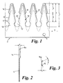
- Figs. 1 and 2 illustrate a part of a comb plate 2 which may consist of a series of identical teeth 4 produced, for example, from a spring steel sheet lmm to 1.5mm thick.
- Bolt holes 6 are provided at intervals in the comb plate for attachment of the plate to a stripper drum with the teeth projecting radially outwards.
- the tooth profile has a tapering radially outer portion 8 and an inner root portion 10 having a substantially arcuate edge forming root openings 12 between adjacent teeth having a maximum width greater than the spacing between the teeth at the junction of the root and outer portions.
- Fig 1 also illustrates the shape of the blank in these regions in broken lines.
- the root portions of the teeth are left unflanged.
- the depth of the flanges reduces progressively from the inner ends but at the extreme outer tip 8a of each tooth the flange depth is increased.
- the height c of the flange reduces from 5.3 mm at its inner end to 4.7 mm adjacent to the tip.
- the height d increases to 6mm.
- the height may be varied between 1 and 10 mm but it is preferably in the range of 3 to 8 mm.
- the flange here may project between 1 and 10mm beyond the main flanges, and is preferably at least 25% deeper than the main flanges, although it may be twice as deep as the main flanges, or more.
- the ratio b/f 0.55 and its most preferred range is 0.65 to 0.4.
- the ratio b/f can be varied between 0.1 and 0.9, but is desirably kept within the range 0.2 to 0.8.
- the angle e between the normal to the main plane of the tooth and the tangent to the outer edge region of the flange 14 is 23°.
- the preferred range of angle is between 0° and 60°.
- the flange 14 is shown with a relatively small radius of curvature at its junction 14a with the main body of the tooth, but it may be continuously curved over at least the greater part of its depth, preferably with a substantially constant radius of curvature.
- the stripping effect of the known toothing profile referred to, with the bulbous root openings formed between adjacent teeth is believed to be significantly dependent on the "keyhole" form imparted by the re-entrant edges of the teeth. It will be noted from Fig. 1 that the flanging along the outer regions of the tapering outer portions of the teeth can provide a further re-entrant region where the flanging terminates.
- the stripping effect can be enhanced by this modification of the tooth profile.
- the width of the gap between the teeth at the inner ends of flanges 16 is approximately equal to the gap at the necks of the root portions.
- Fig 1 also illustrates a backing plate 18 of considerably thicker plastics material which is clamped against the back face of the comb plate to support it against flexure under load.
- the backing plate has teeth 20 which lie within the profile of the comb plate teeth so they are not exposed to abrasion from the crop through which the teeth move.
- the backing plate teeth 20 preferably extend into the flanged outer regions of the comb plate teeth 4 but end short of the tips of the teeth 4. Preferably they extend over the inner 20-50% of the radial length of the comb teeth flanging. In the illustrated example the figure is approximately 30%.
- a backing plate for support in the circumferential direction can help to spread the flexural deflection of the comb plate over a greater part of its radial extent, so increasing the maximum flexure that can be imposed without exceeding the elastic limit of the material.
- Such backing plates also allow the use of a relatively thin metal plate which would otherwise bend too easily to circumferential forces in use.
- the backing plates may also be of metal, but because they are also largely kept out of direct contact with the crop it is also convenient to use plastics materials.
- Fig. 4 illustrates toothing according to the invention mounted in place in a crop stripper rotor to show preferred modified toothing forms used at the ends of the stripper rotor.
- the rotor comprises two drums 60a, 60b mounted coaxially side by side in the stripper on a common drive shaft (not shown).
- the crop stripper is indicated only fragmentarily as in this embodiment, like the preceding embodiment, it can be of generally known form, as shown in Fig. 5.
- the division of the rotor in this manner allows the length to be increased by providing a support for the drive shaft intermediate its length.
- Each drum is therefore rotatably supported at one end in a side plate 62a or 62b of the stripper frame and at the other end in a central division plate 64 of the frame.
- each drum carries toothing of the form shown in Figs 1-3.
- angled ribs 66, 68 on the side plates and the central plate respectively overlap the ends of the drum to divert crop stems away from the supporting plates of the stripper frame where they can wrap around the rotor shaft.
- the toothing is modified in these regions accordingly.
- W093/13462 where such arrangements are described in more detail.
- Fig. 5 shows a crop stripper 100 having a rotor with the toothing described above.
- the crop stripper 100 is intended to be fitted to a combine harvester (not shown) in place of the conventional header with cutter bar and receives its drive from a power take-off shaft (not shown) in the known manner.
- the rotor 102 of the stripper comprises a central drum or core 102' with rows 104 of the toothing projecting radially at equal angular intervals about its periphery.
- the rotor may have a single drum or multiple, co-axial drums as indicated earlier.
- the crop stripper is supported above the ground so that, in use, the rotor teeth can engage the lowest crop parts to be stripped.
- the rotor 102 is located within a downwardly open casing 108 comprising side walls 110, indicated only schematically, and a front cover 112 that is adjustable, as indicated by the arrows U, to vary the front clearance to suit the crop.
- the stripper 100 is driven forwards into the crop, in the arrowed direction V, as the rotor turns about its central axis A in the clockwise direction W, as seen in the drawing, to strip the crop, eg. to remove the grain or grain heads from standing cereal plants.
- the stripped crop is thrown backwards within the casing, directly into an auger 114, or carried to the auger on a conveyor belt 116. From the auger 114 the crop is transferred into hoppers in the combine harvester body in conventional manner that needs no further description.
- the flanged toothing forms described above can be arranged to be mounted on the stripper rotor 102 so that the flanges project forwards or rearwards in the direction of rotation.
- the mounting means (not shown) on the rotor allow the same comb plate to be mounted facing in either direction.
- the user can then choose the manner of mounting in accordance with the type of crop to be harvested.
- crops from which the parts to be gathered are very readily detachable can be harvested with the flanges directed rearwardly with respect to the direction of rotation, their radiussed edges then being brought against the plants to reduce any tendency of other parts of the plants to be detached. With crops which require a more aggressive stripping action to remove the wanted parts, this may be more readily achieved if the flanges are directed forwardly.
Landscapes
- Life Sciences & Earth Sciences (AREA)
- Environmental Sciences (AREA)
- Apparatuses For Bulk Treatment Of Fruits And Vegetables And Apparatuses For Preparing Feeds (AREA)
- Harvester Elements (AREA)
- Outside Dividers And Delivering Mechanisms For Harvesters (AREA)
- Fodder In General (AREA)
- Agricultural Chemicals And Associated Chemicals (AREA)
Applications Claiming Priority (2)
| Application Number | Priority Date | Filing Date | Title |
|---|---|---|---|
| GB9816213 | 1998-07-24 | ||
| GBGB9816213.4A GB9816213D0 (en) | 1998-07-24 | 1998-07-24 | Crop strippers and stripper toothing |
Publications (3)
| Publication Number | Publication Date |
|---|---|
| EP0976315A2 true EP0976315A2 (de) | 2000-02-02 |
| EP0976315A3 EP0976315A3 (de) | 2000-05-10 |
| EP0976315B1 EP0976315B1 (de) | 2004-04-07 |
Family
ID=10836158
Family Applications (1)
| Application Number | Title | Priority Date | Filing Date |
|---|---|---|---|
| EP99305858A Expired - Lifetime EP0976315B1 (de) | 1998-07-24 | 1999-07-23 | Abstreifer für Früchte und Zinken-Abstreifer |
Country Status (6)
| Country | Link |
|---|---|
| US (1) | US6315659B1 (de) |
| EP (1) | EP0976315B1 (de) |
| AT (1) | ATE263479T1 (de) |
| AU (1) | AU759771B2 (de) |
| DE (1) | DE69916183T2 (de) |
| GB (1) | GB9816213D0 (de) |
Cited By (1)
| Publication number | Priority date | Publication date | Assignee | Title |
|---|---|---|---|---|
| RU2468562C2 (ru) * | 2010-07-01 | 2012-12-10 | Государственное научное учреждение Северо-Кавказский научно-исследовательский институт механизации и электрификации сельского хозяйства Российской академии сельскохозяйственных наук (ГНУ СКНИИМЭСХ Россельхозакадемии) | Способ адаптации очесывающего устройства для уборки зерновых колосовых культур с разными характеристиками хлебостоя и средство для его осуществления |
Families Citing this family (14)
| Publication number | Priority date | Publication date | Assignee | Title |
|---|---|---|---|---|
| US6960131B2 (en) * | 2003-11-14 | 2005-11-01 | Td Moser Farms, L.L.C. | Green cicer bean harvesting apparatus and method |
| US9017335B2 (en) | 2007-11-19 | 2015-04-28 | Blue Ortho | Hip implant registration in computer assisted surgery |
| US8869498B1 (en) | 2014-04-04 | 2014-10-28 | Martin Bremmer | Handheld harvester apparatus |
| CN105594370A (zh) * | 2015-11-12 | 2016-05-25 | 南京林业大学 | 柠条种子采集装置 |
| CN105594371B (zh) * | 2015-11-12 | 2019-02-05 | 南京林业大学 | 复合式柠条种子采集装置 |
| RU2646054C1 (ru) * | 2017-04-04 | 2018-03-01 | федеральное государственное бюджетное образовательное учреждение высшего образования "Пензенский государственный аграрный университет" | Съёмная гребёнка очёсывающего оборудования |
| US10807098B1 (en) | 2017-07-26 | 2020-10-20 | Pearson Incorporated | Systems and methods for step grinding |
| US11224168B1 (en) | 2019-04-24 | 2022-01-18 | Martin Bremmer | Handheld harvester apparatus |
| AR116260A1 (es) * | 2019-08-02 | 2021-04-21 | Huergo Hector Augusto | Cabezal para cosecha |
| US10757860B1 (en) | 2019-10-31 | 2020-09-01 | Hemp Processing Solutions, LLC | Stripper apparatus crop harvesting system |
| US10933424B1 (en) | 2019-12-11 | 2021-03-02 | Pearson Incorporated | Grinding roll improvements |
| US20220232769A1 (en) | 2021-01-28 | 2022-07-28 | Cnh Industrial America Llc | Compact and moveable harvesting system for harvesting around obstacles in a field |
| WO2024006485A1 (en) * | 2022-06-29 | 2024-01-04 | Applequist Mfg., Inc. | Crop stripper rotor with alignment and mounting system for stripper teeth sections |
| US20250261588A1 (en) * | 2024-02-21 | 2025-08-21 | Concurrent Engineering Inc. | Multi section flexible stripper header |
Citations (4)
| Publication number | Priority date | Publication date | Assignee | Title |
|---|---|---|---|---|
| WO1986001972A1 (en) | 1984-09-27 | 1986-04-10 | National Research Development Corporation | Crop harvesting apparatus and methods |
| WO1992008339A1 (en) | 1990-11-12 | 1992-05-29 | Shelbourne Reynolds Engineering Ltd. | Crop strippers |
| WO1993013462A1 (fr) | 1991-12-27 | 1993-07-08 | Fuji Photo Film Co., Ltd. | Procede pour la formation d'images par transfert electrophotographique |
| WO1996004776A1 (en) | 1994-08-11 | 1996-02-22 | Shelbourne Reynolds Engineering Ltd. | Crop strippers and stripper toothing |
Family Cites Families (15)
| Publication number | Priority date | Publication date | Assignee | Title |
|---|---|---|---|---|
| US2231354A (en) | 1940-03-19 | 1941-02-11 | Wilcox Everett | Variable stripping teeth |
| US2481652A (en) | 1947-07-25 | 1949-09-13 | Robert W Fort | Seed harvester |
| DK214682A (da) * | 1981-05-15 | 1982-11-16 | Nat Res Dev | Fremgangsmaade og apparat til behandling af afgroede |
| US4991385A (en) * | 1984-09-27 | 1991-02-12 | National Research Development Corporation | Crop harvesting apparatus and methods |
| US4951453A (en) * | 1984-09-27 | 1990-08-28 | National Research Development Corporation | Crop harvesting apparatus and methods |
| US4843806A (en) * | 1984-09-27 | 1989-07-04 | National Research Development Corporation | Crop harvesting apparatus and methods |
| GB8608585D0 (en) | 1986-04-09 | 1986-05-14 | British Res Agricult Eng | Crop harvesting apparatus |
| WO1988004885A1 (en) | 1987-01-05 | 1988-07-14 | Klinner Wilfred E | Apparatus and method for harvesting crops |
| WO1988005626A1 (en) | 1987-02-05 | 1988-08-11 | Klinner Wilfred E | Apparatus and method for harvesting crops by stripping |
| AU1159888A (en) * | 1987-02-05 | 1988-08-24 | Wilfred Erwin Klinner | Apparatus and method for harvesting crops by stripping |
| AU622432B2 (en) | 1988-02-01 | 1992-04-09 | Wilfred Erwin Klinner | Apparatus and method for selective crop harvesting |
| GB8918015D0 (en) | 1989-08-07 | 1989-09-20 | British Res Agricult Eng | Crop harvesting apparatus |
| WO1992003037A1 (en) | 1990-08-14 | 1992-03-05 | Klinner Wilfred E | Means and method of securing and protecting crop engaging elements |
| DE69109659T2 (de) * | 1990-10-12 | 1995-09-28 | British Technology Group Ltd., London | Messvorrichtung für erntegut. |
| GB9200726D0 (en) * | 1992-01-14 | 1992-03-11 | Shelbourne Reynolds Eng | Stripper drums |
-
1998
- 1998-07-24 GB GBGB9816213.4A patent/GB9816213D0/en not_active Ceased
-
1999
- 1999-07-22 US US09/358,857 patent/US6315659B1/en not_active Expired - Lifetime
- 1999-07-23 AT AT99305858T patent/ATE263479T1/de not_active IP Right Cessation
- 1999-07-23 DE DE69916183T patent/DE69916183T2/de not_active Expired - Lifetime
- 1999-07-23 AU AU41104/99A patent/AU759771B2/en not_active Expired
- 1999-07-23 EP EP99305858A patent/EP0976315B1/de not_active Expired - Lifetime
Patent Citations (5)
| Publication number | Priority date | Publication date | Assignee | Title |
|---|---|---|---|---|
| WO1986001972A1 (en) | 1984-09-27 | 1986-04-10 | National Research Development Corporation | Crop harvesting apparatus and methods |
| WO1992008339A1 (en) | 1990-11-12 | 1992-05-29 | Shelbourne Reynolds Engineering Ltd. | Crop strippers |
| US5389038A (en) | 1990-11-12 | 1995-02-14 | Shelbourne Reynolds Engineering Ltd. | Crop strippers |
| WO1993013462A1 (fr) | 1991-12-27 | 1993-07-08 | Fuji Photo Film Co., Ltd. | Procede pour la formation d'images par transfert electrophotographique |
| WO1996004776A1 (en) | 1994-08-11 | 1996-02-22 | Shelbourne Reynolds Engineering Ltd. | Crop strippers and stripper toothing |
Cited By (1)
| Publication number | Priority date | Publication date | Assignee | Title |
|---|---|---|---|---|
| RU2468562C2 (ru) * | 2010-07-01 | 2012-12-10 | Государственное научное учреждение Северо-Кавказский научно-исследовательский институт механизации и электрификации сельского хозяйства Российской академии сельскохозяйственных наук (ГНУ СКНИИМЭСХ Россельхозакадемии) | Способ адаптации очесывающего устройства для уборки зерновых колосовых культур с разными характеристиками хлебостоя и средство для его осуществления |
Also Published As
| Publication number | Publication date |
|---|---|
| AU4110499A (en) | 2000-02-17 |
| ATE263479T1 (de) | 2004-04-15 |
| US6315659B1 (en) | 2001-11-13 |
| EP0976315B1 (de) | 2004-04-07 |
| EP0976315A3 (de) | 2000-05-10 |
| AU759771B2 (en) | 2003-05-01 |
| DE69916183T2 (de) | 2004-11-25 |
| GB9816213D0 (en) | 1998-09-23 |
| DE69916183D1 (de) | 2004-05-13 |
Similar Documents
| Publication | Publication Date | Title |
|---|---|---|
| EP0976315B1 (de) | Abstreifer für Früchte und Zinken-Abstreifer | |
| EP0014707B2 (de) | Verfahren und vorrichtung zum konditionieren von getreide | |
| EP0340229B1 (de) | Apparat und verfahren zum ernten von feldfrüchten | |
| CA1159333A (en) | Separator for an axial flow rotary combine | |
| US8205424B1 (en) | Baler pre-cutter rotor design having reinforced tines | |
| CA2059686C (en) | Sectional rasp bar assemblies for combine threshing cylinders | |
| CA2453199C (en) | Machine for mowing stalk-like crops and remover that can be disassembled | |
| EP0495938B1 (de) | Mittel und verfahren zum sichern und schützen von ernte erfassenden teilen | |
| AU657716B2 (en) | Crop strippers | |
| EP0622986B1 (de) | Abstreiftrommeln | |
| US3803820A (en) | Powered rotor for row crop harvesters | |
| US3807152A (en) | Powered rotor for row crop harvesters and stripper bar therefor | |
| EP0418243A1 (de) | Vorrichtung und verfahren zum selektiven ernten | |
| WO1996004776A1 (en) | Crop strippers and stripper toothing | |
| US4592194A (en) | Processing apparatus for stalk-shaped agricultural products | |
| US20260013439A1 (en) | Improved rake wheel assemblies and methods of making the same | |
| US2292679A (en) | Rotary beater | |
| EP0300004A1 (de) | Verfahren und apparat zum aufbereiten von mähgut | |
| CN110637607B (zh) | 一种履带式匍匐藤茎类作物茎叶联合收获作业机 | |
| GB2209263A (en) | Improved cutter means | |
| RU1794360C (ru) | Очиститель головок корнеплодов от ботвы на корню | |
| RU2370939C1 (ru) | Устройство для транспортировки и очистки корнеплодов | |
| EP0169945A1 (de) | Reihenpflanzensammelgerät für Feldhäcksler | |
| JPH0795895B2 (ja) | コンバインの脱穀装置 |
Legal Events
| Date | Code | Title | Description |
|---|---|---|---|
| PUAI | Public reference made under article 153(3) epc to a published international application that has entered the european phase |
Free format text: ORIGINAL CODE: 0009012 |
|
| AK | Designated contracting states |
Kind code of ref document: A2 Designated state(s): AT BE CH CY DE DK ES FI FR GB GR IE IT LI LU MC NL PT SE |
|
| AX | Request for extension of the european patent |
Free format text: AL;LT;LV;MK;RO;SI |
|
| PUAL | Search report despatched |
Free format text: ORIGINAL CODE: 0009013 |
|
| AK | Designated contracting states |
Kind code of ref document: A3 Designated state(s): AT BE CH CY DE DK ES FI FR GB GR IE IT LI LU MC NL PT SE |
|
| AX | Request for extension of the european patent |
Free format text: AL;LT;LV;MK;RO;SI |
|
| 17P | Request for examination filed |
Effective date: 20001107 |
|
| AKX | Designation fees paid |
Free format text: AT BE CH CY DE DK ES FI FR GB GR IE IT LI LU MC NL PT SE |
|
| GRAP | Despatch of communication of intention to grant a patent |
Free format text: ORIGINAL CODE: EPIDOSNIGR1 |
|
| GRAS | Grant fee paid |
Free format text: ORIGINAL CODE: EPIDOSNIGR3 |
|
| GRAA | (expected) grant |
Free format text: ORIGINAL CODE: 0009210 |
|
| AK | Designated contracting states |
Kind code of ref document: B1 Designated state(s): AT BE CH CY DE DK ES FI FR GB GR IE IT LI LU MC NL PT SE |
|
| PG25 | Lapsed in a contracting state [announced via postgrant information from national office to epo] |
Ref country code: NL Free format text: LAPSE BECAUSE OF FAILURE TO SUBMIT A TRANSLATION OF THE DESCRIPTION OR TO PAY THE FEE WITHIN THE PRESCRIBED TIME-LIMIT Effective date: 20040407 Ref country code: LI Free format text: LAPSE BECAUSE OF FAILURE TO SUBMIT A TRANSLATION OF THE DESCRIPTION OR TO PAY THE FEE WITHIN THE PRESCRIBED TIME-LIMIT Effective date: 20040407 Ref country code: IT Free format text: LAPSE BECAUSE OF FAILURE TO SUBMIT A TRANSLATION OF THE DESCRIPTION OR TO PAY THE FEE WITHIN THE PRESCRIBED TIME-LIMIT;WARNING: LAPSES OF ITALIAN PATENTS WITH EFFECTIVE DATE BEFORE 2007 MAY HAVE OCCURRED AT ANY TIME BEFORE 2007. THE CORRECT EFFECTIVE DATE MAY BE DIFFERENT FROM THE ONE RECORDED. Effective date: 20040407 Ref country code: FI Free format text: LAPSE BECAUSE OF FAILURE TO SUBMIT A TRANSLATION OF THE DESCRIPTION OR TO PAY THE FEE WITHIN THE PRESCRIBED TIME-LIMIT Effective date: 20040407 Ref country code: CY Free format text: LAPSE BECAUSE OF FAILURE TO SUBMIT A TRANSLATION OF THE DESCRIPTION OR TO PAY THE FEE WITHIN THE PRESCRIBED TIME-LIMIT Effective date: 20040407 Ref country code: CH Free format text: LAPSE BECAUSE OF FAILURE TO SUBMIT A TRANSLATION OF THE DESCRIPTION OR TO PAY THE FEE WITHIN THE PRESCRIBED TIME-LIMIT Effective date: 20040407 Ref country code: AT Free format text: LAPSE BECAUSE OF FAILURE TO SUBMIT A TRANSLATION OF THE DESCRIPTION OR TO PAY THE FEE WITHIN THE PRESCRIBED TIME-LIMIT Effective date: 20040407 |
|
| REG | Reference to a national code |
Ref country code: GB Ref legal event code: FG4D |
|
| REG | Reference to a national code |
Ref country code: CH Ref legal event code: EP |
|
| REF | Corresponds to: |
Ref document number: 69916183 Country of ref document: DE Date of ref document: 20040513 Kind code of ref document: P |
|
| REG | Reference to a national code |
Ref country code: IE Ref legal event code: FG4D |
|
| PG25 | Lapsed in a contracting state [announced via postgrant information from national office to epo] |
Ref country code: SE Free format text: LAPSE BECAUSE OF FAILURE TO SUBMIT A TRANSLATION OF THE DESCRIPTION OR TO PAY THE FEE WITHIN THE PRESCRIBED TIME-LIMIT Effective date: 20040707 Ref country code: GR Free format text: LAPSE BECAUSE OF FAILURE TO SUBMIT A TRANSLATION OF THE DESCRIPTION OR TO PAY THE FEE WITHIN THE PRESCRIBED TIME-LIMIT Effective date: 20040707 Ref country code: DK Free format text: LAPSE BECAUSE OF FAILURE TO SUBMIT A TRANSLATION OF THE DESCRIPTION OR TO PAY THE FEE WITHIN THE PRESCRIBED TIME-LIMIT Effective date: 20040707 |
|
| PG25 | Lapsed in a contracting state [announced via postgrant information from national office to epo] |
Ref country code: ES Free format text: LAPSE BECAUSE OF FAILURE TO SUBMIT A TRANSLATION OF THE DESCRIPTION OR TO PAY THE FEE WITHIN THE PRESCRIBED TIME-LIMIT Effective date: 20040718 |
|
| PG25 | Lapsed in a contracting state [announced via postgrant information from national office to epo] |
Ref country code: LU Free format text: LAPSE BECAUSE OF NON-PAYMENT OF DUE FEES Effective date: 20040723 Ref country code: IE Free format text: LAPSE BECAUSE OF NON-PAYMENT OF DUE FEES Effective date: 20040723 |
|
| PG25 | Lapsed in a contracting state [announced via postgrant information from national office to epo] |
Ref country code: MC Free format text: LAPSE BECAUSE OF NON-PAYMENT OF DUE FEES Effective date: 20040731 |
|
| NLV1 | Nl: lapsed or annulled due to failure to fulfill the requirements of art. 29p and 29m of the patents act | ||
| REG | Reference to a national code |
Ref country code: CH Ref legal event code: PL |
|
| ET | Fr: translation filed | ||
| PLBE | No opposition filed within time limit |
Free format text: ORIGINAL CODE: 0009261 |
|
| STAA | Information on the status of an ep patent application or granted ep patent |
Free format text: STATUS: NO OPPOSITION FILED WITHIN TIME LIMIT |
|
| 26N | No opposition filed |
Effective date: 20050110 |
|
| REG | Reference to a national code |
Ref country code: IE Ref legal event code: MM4A |
|
| PG25 | Lapsed in a contracting state [announced via postgrant information from national office to epo] |
Ref country code: PT Free format text: LAPSE BECAUSE OF NON-PAYMENT OF DUE FEES Effective date: 20040907 |
|
| REG | Reference to a national code |
Ref country code: FR Ref legal event code: PLFP Year of fee payment: 18 |
|
| REG | Reference to a national code |
Ref country code: FR Ref legal event code: PLFP Year of fee payment: 19 |
|
| REG | Reference to a national code |
Ref country code: FR Ref legal event code: PLFP Year of fee payment: 20 |
|
| PGFP | Annual fee paid to national office [announced via postgrant information from national office to epo] |
Ref country code: BE Payment date: 20180531 Year of fee payment: 20 Ref country code: FR Payment date: 20180524 Year of fee payment: 20 |
|
| PGFP | Annual fee paid to national office [announced via postgrant information from national office to epo] |
Ref country code: DE Payment date: 20180525 Year of fee payment: 20 Ref country code: GB Payment date: 20180517 Year of fee payment: 20 |
|
| REG | Reference to a national code |
Ref country code: DE Ref legal event code: R071 Ref document number: 69916183 Country of ref document: DE |
|
| REG | Reference to a national code |
Ref country code: GB Ref legal event code: PE20 Expiry date: 20190722 |
|
| REG | Reference to a national code |
Ref country code: BE Ref legal event code: MK Effective date: 20190723 |
|
| PG25 | Lapsed in a contracting state [announced via postgrant information from national office to epo] |
Ref country code: GB Free format text: LAPSE BECAUSE OF EXPIRATION OF PROTECTION Effective date: 20190722 |