EP0976342A2 - Dispositif de maintien d'un objet, en particulier d'un parasol - Google Patents
Dispositif de maintien d'un objet, en particulier d'un parasol Download PDFInfo
- Publication number
- EP0976342A2 EP0976342A2 EP99114582A EP99114582A EP0976342A2 EP 0976342 A2 EP0976342 A2 EP 0976342A2 EP 99114582 A EP99114582 A EP 99114582A EP 99114582 A EP99114582 A EP 99114582A EP 0976342 A2 EP0976342 A2 EP 0976342A2
- Authority
- EP
- European Patent Office
- Prior art keywords
- claw
- holding
- push rod
- elements
- receiving element
- Prior art date
- Legal status (The legal status is an assumption and is not a legal conclusion. Google has not performed a legal analysis and makes no representation as to the accuracy of the status listed.)
- Granted
Links
- 210000000078 claw Anatomy 0.000 claims description 35
- 230000008878 coupling Effects 0.000 claims description 7
- 238000010168 coupling process Methods 0.000 claims description 7
- 238000005859 coupling reaction Methods 0.000 claims description 7
- 238000003825 pressing Methods 0.000 claims description 2
- 244000025254 Cannabis sativa Species 0.000 description 1
- 238000013016 damping Methods 0.000 description 1
- 230000000694 effects Effects 0.000 description 1
- 238000004519 manufacturing process Methods 0.000 description 1
- 239000002184 metal Substances 0.000 description 1
- 239000004576 sand Substances 0.000 description 1
- XLYOFNOQVPJJNP-UHFFFAOYSA-N water Substances O XLYOFNOQVPJJNP-UHFFFAOYSA-N 0.000 description 1
Images


Classifications
-
- E—FIXED CONSTRUCTIONS
- E04—BUILDING
- E04H—BUILDINGS OR LIKE STRUCTURES FOR PARTICULAR PURPOSES; SWIMMING OR SPLASH BATHS OR POOLS; MASTS; FENCING; TENTS OR CANOPIES, IN GENERAL
- E04H12/00—Towers; Masts or poles; Chimney stacks; Water-towers; Methods of erecting such structures
- E04H12/22—Sockets or holders for poles or posts
- E04H12/2207—Sockets or holders for poles or posts not used
- E04H12/2215—Sockets or holders for poles or posts not used driven into the ground
- E04H12/223—Sockets or holders for poles or posts not used driven into the ground with movable anchoring elements; with separately driven anchor rods
Definitions
- the present invention relates to a device for Holding an object, especially an umbrella, a clothes dryer or the like. With a holding element for the Object.
- Such devices are in the most varied of forms and Execution known and available on the market. You serve essentially for picking up an object, especially an umbrella. They instruct preferably round or polygonal holding element, which is mostly difficult.
- This can be as Metal plate or as a plastic container for filling be made of water. In this plastic container or a receiving element engages in this receiving plate into which, for example, an object such as a clothesline or a parasol inserted or attached to it can be.
- This appropriate facilities not good stability and immediately in light or stronger winds topple over. They also have a high weight and are difficult to transport.
- the present invention has for its object a Establishment of the above Way of creating which one any object, especially an umbrella or a Clothesline safe and secure anywhere can be set up without the underground, in particular damage the lawn. Furthermore, the total weight of the Setup can be significantly reduced and a compact handy size can be created for transport.
- the holding element leads to arranged at a distance from a base is.
- At least one end of the tie rod elements engages or pushrod elements arranged claw element in a surface.
- the drawbar and Push rod elements are with a receiving element of the Holding element preferably connected in an articulated manner.
- the present invention is also intended to lie in that
- the tie rod element is fixed to the receiving element can be connected. E.g. can this be angular or even be plugged onto this at right angles.
- the claw elements are then preferably provided in an articulated manner, which has a push rod element around the joint are arranged pivotably.
- others can Devices such as spring elements, hydraulic cylinders, Racks or the like.
- the holding element can be placed in a subsurface, especially dig into the ground. That way it will Holding element, for example in the sand on the ground, the turf fixed. It is also an advantage if the individual tie rod and push rod elements of the Holding element are spaced from the ground and this do not touch.
- the Tie rod elements rest on the ground and at the end only the claw elements in the underground intervention. It is also considered different Arrangements of push rod and tie rod elements on the To provide the receiving element. It can be angled in about three or four rectangular rods and / or Project the push rod elements from the receiving element. Here there should be no limits to the invention.
- the loading or pivoting of the Claw elements, which end of the tie rod and / or Push rod elements are arranged, is preferably done by moving one on or on the receiving element guided sliding sleeve. At this are the individual Push rod elements coupled.
- sliding sleeve instead of the sliding sleeve, rail grooves, Racks or the like can be provided to pivot the claw elements around the tie rod element enable.
- the receiving element is preferably in two parts divided. It can be used as a rubber element, spring element or the like. be made.
- the holding device pressurized object laterally, e.g. by a strong wind or a gust of wind, so there the subject of the compressive stress. A jerky The device is pulled out of the underground prevented this way.
- the coupling piece has a damping effect to jerky pressure loads on the used Object. This is also said to be from the present Invention to be included.
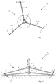
- a device R 1 has a holding element 1, which is essentially formed from a receiving element 2, in particular a tube, and connecting rod element 3 and / or pressure rod elements 4 adjoining it in an articulated manner.
- the push rod and tie rod elements (3, 4) are fixed at a preferred angle ⁇ of 120 ° to the receiving element 2 at the respective angle ⁇ .
- only two tie rod elements 3 projecting from the receiving element 2 are shown, which are fixed at the ends on the receiving element 2 to joints 5.
- movable sliding sleeve 6 which opposite the tie rod elements 3 fixed on the receiving element 2 is movable.
- Push rod elements 4 via further joints 5.
- the claw elements 8 can Shovel-like, possibly made of several individual elements be educated. At the bottom they are pointed and possibly arched. They are used to get into one Intervene underground 9 in particular in a turf. However, the claw elements 8 are preferably pointed trained to intervene in the Underground 9 is relieved.
- an object 10 be releasably set again.
- the Item 10 as a parasol or as a clothesline educated.
- the receiving element 2 is designed as a tube, can the object 10 or parasol in this be inserted in a known manner.
- the holding element 1 of the device R 1 is spaced from the base 9. It is placed on the base 9 at a distance by means of the claw elements 8. Subsequent action on the sliding sleeve 6 and / or moving the push rod elements 4 outwards causes the at least one claw element 8 to pivot about the pull rod 3. This pivoting movement causes the device R 1 to be buried into the ground 9 by the preferably curved claw elements 8.
- the end Claw element 8 can be easily moved into the ground 9, for example by applying pressure with a hammer or one foot.
- at least one claw element 8 is movable is assigned to the holding element 1.
- Drawbar or push rod elements (3, 4) can, for example. the claw element 8 be fixed. Then these will For example, manually inserted into the ground.
- Those assigned to the base 9 are preferred Tie rod elements 3 and slightly angularly spaced don't touch it. This way the underground 9, especially a meadow, grass or the like. Protected and not damaged.
- the device R 1 is detached from the base 9 in the opposite manner by moving the sliding sleeve 6 upwards, as a result of which the claw elements 8 are pivoted back and out of the base 9.
- the device R 1 can then be cleaned and, as is shown in particular in FIG. 3, be folded against a lower end 11 by moving the sliding sleeve 6 in the double arrow direction shown.
- the device R 1 can be easily stowed away and easily transported. Unfolding into a position of use takes place by moving the sliding sleeve 6 back.
- a device R 2 is shown in which the sliding sleeve 6 is provided near the lower end 11.
- the push rod elements 4 protrude from this in an articulated manner and are connected at the other end to the claw element 8.
- FIGS. 5a and 5b Two further exemplary embodiments of further devices R 3 and R 4 are shown in FIGS. 5a and 5b.
- four tie rod elements 3 and / or push rod elements 4 preferably connect to the receiving element 2 in a star shape.
- at least two of the protruding link or push rod elements 3, 4 are provided with the movable claw elements 8 described above.
- At least one claw element 8 is also shown in FIG pivotable as described above. However, there are also all corresponding as tie rods or Push rod elements 3, 4 trained boom with corresponding movable claw elements 8 provided.
- a device R 4 is also shown in a further exemplary embodiment, in which two legs 12 are connected to one another at an angle, possibly in an articulated manner.
- the two legs 12 are preferably connected to one another via a cross member 13.
- the receiving element 2 attacks.
- the sliding sleeve 6 sits on this in the manner described above, to which push rod elements 4 are connected and at the ends are connected in an articulated manner via the connecting joints 7 to claw elements 8.
- the third claw element 8, which is provided at the connection point between the two legs 12, can also be designed to be movable, but also fixed, as shown here.
- the device R 1 is essentially shown, as shown in FIG. 2.
- an actuating element 13 is assigned to the holding element 1, which is articulated to the end of the rod element 3.
- the actuating element 13 with the sleeve 6 is over a connecting element 14, in particular wire rope or the like. connected.
- a connecting element 14 in particular wire rope or the like. connected.
- a coupling piece 15 is inserted into the receiving element 2, which is of an elastic type. This can be rubber-like or spring element-like. If, for example, an object 10 is laterally pressurized, for example by a gust of wind or wind, it gives way through the coupling piece 15 and can be pivoted about it. If the pressure is not applied, the object 10 is automatically pivoted back into its original position, as shown in the double arrow direction.
- Item number list 1 Holding element 34 67 2nd Receiving element 35 68 3rd Drawbar element 36 69 4th Push rods ⁇ -> 37 70 element 5 joint 38 71 6 Sliding sleeve 39 72 7 Connection ⁇ -> 40 73 joint 8th Claw element 41 74 9 Underground 42 75 10th object 43 76 11 Lower end 44 77 12th leg 45 78 13 Actuator 46 79 14 Fastener 47 15 Coupling piece 48 16 49 17th 50 R 1 Facility 18th 51 R 2 Facility 19th 52 R 3 Facility 20th 53 R 4 Facility 21 54 22 55 ⁇ angle 23 56 24th 57 25th 58 26 59 27 60 28 61 29 62 30th 63 31 64 32 65 33 66
Landscapes
- Engineering & Computer Science (AREA)
- Architecture (AREA)
- Civil Engineering (AREA)
- Structural Engineering (AREA)
- Manipulator (AREA)
- Holders For Apparel And Elements Relating To Apparel (AREA)
- Drying Of Solid Materials (AREA)
- Accessory Of Washing/Drying Machine, Commercial Washing/Drying Machine, Other Washing/Drying Machine (AREA)
- Handcart (AREA)
- Load-Engaging Elements For Cranes (AREA)
- Tents Or Canopies (AREA)
Applications Claiming Priority (2)
| Application Number | Priority Date | Filing Date | Title |
|---|---|---|---|
| DE19834366 | 1998-07-30 | ||
| DE19834366A DE19834366A1 (de) | 1998-07-30 | 1998-07-30 | Einrichtung zum Halten eines Gegenstandes, insbesondere eines Sonnenschirmes |
Publications (3)
| Publication Number | Publication Date |
|---|---|
| EP0976342A2 true EP0976342A2 (fr) | 2000-02-02 |
| EP0976342A3 EP0976342A3 (fr) | 2001-04-11 |
| EP0976342B1 EP0976342B1 (fr) | 2003-04-23 |
Family
ID=7875851
Family Applications (1)
| Application Number | Title | Priority Date | Filing Date |
|---|---|---|---|
| EP99114582A Expired - Lifetime EP0976342B1 (fr) | 1998-07-30 | 1999-07-26 | Dispositif de maintien d'un objet, en particulier d'un parasol |
Country Status (3)
| Country | Link |
|---|---|
| EP (1) | EP0976342B1 (fr) |
| AT (1) | ATE237968T1 (fr) |
| DE (2) | DE19834366A1 (fr) |
Cited By (1)
| Publication number | Priority date | Publication date | Assignee | Title |
|---|---|---|---|---|
| WO2006047895A1 (fr) * | 2004-11-05 | 2006-05-11 | M & H Gmbh | Dispositif d'ancrage d'un poteau dans le sol |
Families Citing this family (1)
| Publication number | Priority date | Publication date | Assignee | Title |
|---|---|---|---|---|
| CN102866035B (zh) * | 2012-09-14 | 2014-06-04 | 东南大学 | 一种小行星取样器的自嵌入式锚固方法 |
Family Cites Families (9)
| Publication number | Priority date | Publication date | Assignee | Title |
|---|---|---|---|---|
| US816268A (en) * | 1905-03-30 | 1906-03-27 | Otto W Steindorf | Tripod for cameras. |
| US856610A (en) * | 1906-07-12 | 1907-06-11 | Otto W Steindorf | Tripod. |
| US1099505A (en) * | 1914-01-08 | 1914-06-09 | Francis W Smith | Support. |
| US1650747A (en) * | 1921-02-14 | 1927-11-29 | Karl W Thalhammer | Tripod construction |
| US1936428A (en) * | 1931-12-26 | 1933-11-21 | Hettrick Mfg Co | Umbrella-supporting table |
| US4199123A (en) * | 1978-08-16 | 1980-04-22 | Hughes Aircraft Company | Tripod leveling mechanization |
| IT212574Z2 (it) * | 1987-07-03 | 1989-07-23 | Cherichetti Giorgio | Morsetto per il fissaggio di un ombrello parasole ad un passeggino per bambini. |
| GB8902554D0 (en) * | 1989-02-06 | 1989-03-22 | Dugmore Barry | Leisure furniture |
| GB2303546A (en) * | 1995-07-25 | 1997-02-26 | Gregg Hazelgrove | A portable umbrella support |
-
1998
- 1998-07-30 DE DE19834366A patent/DE19834366A1/de not_active Withdrawn
-
1999
- 1999-07-26 DE DE59905146T patent/DE59905146D1/de not_active Expired - Lifetime
- 1999-07-26 EP EP99114582A patent/EP0976342B1/fr not_active Expired - Lifetime
- 1999-07-26 AT AT99114582T patent/ATE237968T1/de not_active IP Right Cessation
Cited By (1)
| Publication number | Priority date | Publication date | Assignee | Title |
|---|---|---|---|---|
| WO2006047895A1 (fr) * | 2004-11-05 | 2006-05-11 | M & H Gmbh | Dispositif d'ancrage d'un poteau dans le sol |
Also Published As
| Publication number | Publication date |
|---|---|
| DE19834366A1 (de) | 2000-02-03 |
| ATE237968T1 (de) | 2003-05-15 |
| EP0976342B1 (fr) | 2003-04-23 |
| EP0976342A3 (fr) | 2001-04-11 |
| DE59905146D1 (de) | 2003-05-28 |
Similar Documents
| Publication | Publication Date | Title |
|---|---|---|
| EP1428788A1 (fr) | Flèche télescopique | |
| DE202019102725U1 (de) | Zentralverriegelungsvorrichtung für ein Faltzelt | |
| EP3569797A1 (fr) | Dispositif de levage pour support mobile | |
| EP0976342B1 (fr) | Dispositif de maintien d'un objet, en particulier d'un parasol | |
| EP0615593A1 (fr) | Support d'ecartement pour canalisations sous-marines | |
| DE4422112C1 (de) | Verlegekarre für Belagelemente | |
| DE1911721U (de) | Bauhilfsgeraet zum spannen von fluchtschnueren an hochzuziehenden mauern, waenden od. dgl. | |
| DE2707182A1 (de) | Durch ein zugfahrzeug ueber eine zugstange ziehbares bodenbearbeitungsgeraet wie egge o.dgl. | |
| DE102015219404A1 (de) | Schirm, insbesondere Standschirm | |
| DE9006546U1 (de) | Verlegegerät für Platten, insbesondere für Terrassen- und Gehwegplatten | |
| DE202009013011U1 (de) | Kescheranordnung | |
| DE585087C (de) | Hebevorrichtung | |
| EP1053700A2 (fr) | Piétement pour tables, tabourets ou objets similaires | |
| DE20013914U1 (de) | Holzspaltgerät mit Vorrichtung zum Ankippen von Spaltmaterial | |
| DE1892222U (de) | Stiel fuer haus- und gartengeraete. | |
| DE1947036A1 (de) | Kultivator mit einstellbarer Schnittbreite | |
| DE2916899A1 (de) | Zangengreifer | |
| DE9315085U1 (de) | Tragezange für Behälter | |
| AT216418B (fr) | ||
| DE2162135B2 (de) | Fahrbarer Hebebock zum Anheben bzw. Absetzen von Containern | |
| DE9203900U1 (de) | Vorrichtung zum Transportieren von schweren Lasten | |
| DE102023129230A1 (de) | Anlage, umfassend einen Stützfuß | |
| AT261956B (de) | Hubstange für das hydraulische Hubwerk von Ackerschleppern | |
| EP0962167A1 (fr) | Table pliante munie d'un piètement portant un dessus de table amovible | |
| AT215721B (de) | Stützstrebe für die unteren Hubwerkslenker von Traktoren |
Legal Events
| Date | Code | Title | Description |
|---|---|---|---|
| PUAI | Public reference made under article 153(3) epc to a published international application that has entered the european phase |
Free format text: ORIGINAL CODE: 0009012 |
|
| AK | Designated contracting states |
Kind code of ref document: A2 Designated state(s): AT CH DE FR IT LI |
|
| AX | Request for extension of the european patent |
Free format text: AL;LT;LV;MK;RO;SI |
|
| RTI1 | Title (correction) |
Free format text: APPARATUS FOR HOLDING AN ARTICLE, IN PARTICULAR A PARASOL |
|
| PUAL | Search report despatched |
Free format text: ORIGINAL CODE: 0009013 |
|
| AK | Designated contracting states |
Kind code of ref document: A3 Designated state(s): AT BE CH CY DE DK ES FI FR GB GR IE IT LI LU MC NL PT SE |
|
| AX | Request for extension of the european patent |
Free format text: AL;LT;LV;MK;RO;SI |
|
| 17P | Request for examination filed |
Effective date: 20010809 |
|
| AKX | Designation fees paid |
Free format text: AT CH DE FR IT LI |
|
| 17Q | First examination report despatched |
Effective date: 20020123 |
|
| GRAG | Despatch of communication of intention to grant |
Free format text: ORIGINAL CODE: EPIDOS AGRA |
|
| GRAG | Despatch of communication of intention to grant |
Free format text: ORIGINAL CODE: EPIDOS AGRA |
|
| GRAH | Despatch of communication of intention to grant a patent |
Free format text: ORIGINAL CODE: EPIDOS IGRA |
|
| GRAH | Despatch of communication of intention to grant a patent |
Free format text: ORIGINAL CODE: EPIDOS IGRA |
|
| GRAA | (expected) grant |
Free format text: ORIGINAL CODE: 0009210 |
|
| AK | Designated contracting states |
Designated state(s): AT CH DE FR IT LI |
|
| REG | Reference to a national code |
Ref country code: CH Ref legal event code: EP |
|
| REF | Corresponds to: |
Ref document number: 59905146 Country of ref document: DE Date of ref document: 20030528 Kind code of ref document: P |
|
| REG | Reference to a national code |
Ref country code: CH Ref legal event code: NV Representative=s name: FREI PATENTANWALTSBUERO |
|
| ET | Fr: translation filed | ||
| PLBE | No opposition filed within time limit |
Free format text: ORIGINAL CODE: 0009261 |
|
| STAA | Information on the status of an ep patent application or granted ep patent |
Free format text: STATUS: NO OPPOSITION FILED WITHIN TIME LIMIT |
|
| 26N | No opposition filed |
Effective date: 20040126 |
|
| PGFP | Annual fee paid to national office [announced via postgrant information from national office to epo] |
Ref country code: FR Payment date: 20090721 Year of fee payment: 11 |
|
| PGFP | Annual fee paid to national office [announced via postgrant information from national office to epo] |
Ref country code: AT Payment date: 20090724 Year of fee payment: 11 |
|
| PGFP | Annual fee paid to national office [announced via postgrant information from national office to epo] |
Ref country code: IT Payment date: 20090725 Year of fee payment: 11 |
|
| REG | Reference to a national code |
Ref country code: FR Ref legal event code: ST Effective date: 20110331 |
|
| PG25 | Lapsed in a contracting state [announced via postgrant information from national office to epo] |
Ref country code: FR Free format text: LAPSE BECAUSE OF NON-PAYMENT OF DUE FEES Effective date: 20100802 Ref country code: AT Free format text: LAPSE BECAUSE OF NON-PAYMENT OF DUE FEES Effective date: 20100726 Ref country code: IT Free format text: LAPSE BECAUSE OF NON-PAYMENT OF DUE FEES Effective date: 20100726 |
|
| PGFP | Annual fee paid to national office [announced via postgrant information from national office to epo] |
Ref country code: CH Payment date: 20110725 Year of fee payment: 13 |
|
| REG | Reference to a national code |
Ref country code: CH Ref legal event code: PL |
|
| PG25 | Lapsed in a contracting state [announced via postgrant information from national office to epo] |
Ref country code: CH Free format text: LAPSE BECAUSE OF NON-PAYMENT OF DUE FEES Effective date: 20130731 Ref country code: LI Free format text: LAPSE BECAUSE OF NON-PAYMENT OF DUE FEES Effective date: 20130731 |
|
| PGFP | Annual fee paid to national office [announced via postgrant information from national office to epo] |
Ref country code: DE Payment date: 20140930 Year of fee payment: 16 |
|
| REG | Reference to a national code |
Ref country code: DE Ref legal event code: R082 Ref document number: 59905146 Country of ref document: DE Representative=s name: PATENTANWAELTE UND RECHTSANWALT WEISS, ARAT & , DE Ref country code: DE Ref legal event code: R082 Ref document number: 59905146 Country of ref document: DE Representative=s name: PATENTANWAELTE UND RECHTSANWALT DR. WEISS, ARA, DE |
|
| REG | Reference to a national code |
Ref country code: DE Ref legal event code: R119 Ref document number: 59905146 Country of ref document: DE |
|
| PG25 | Lapsed in a contracting state [announced via postgrant information from national office to epo] |
Ref country code: DE Free format text: LAPSE BECAUSE OF NON-PAYMENT OF DUE FEES Effective date: 20160202 |