EP0976347A2 - Aide, notamment pour plier une chaise de jardin - Google Patents
Aide, notamment pour plier une chaise de jardin Download PDFInfo
- Publication number
- EP0976347A2 EP0976347A2 EP99108430A EP99108430A EP0976347A2 EP 0976347 A2 EP0976347 A2 EP 0976347A2 EP 99108430 A EP99108430 A EP 99108430A EP 99108430 A EP99108430 A EP 99108430A EP 0976347 A2 EP0976347 A2 EP 0976347A2
- Authority
- EP
- European Patent Office
- Prior art keywords
- armrest
- lifting element
- furniture according
- hinge
- foldable furniture
- Prior art date
- Legal status (The legal status is an assumption and is not a legal conclusion. Google has not performed a legal analysis and makes no representation as to the accuracy of the status listed.)
- Withdrawn
Links
Images

Classifications
-
- A—HUMAN NECESSITIES
- A47—FURNITURE; DOMESTIC ARTICLES OR APPLIANCES; COFFEE MILLS; SPICE MILLS; SUCTION CLEANERS IN GENERAL
- A47C—CHAIRS; SOFAS; BEDS
- A47C1/00—Chairs adapted for special purposes
- A47C1/02—Reclining or easy chairs
- A47C1/022—Reclining or easy chairs having independently-adjustable supporting parts
- A47C1/024—Reclining or easy chairs having independently-adjustable supporting parts the parts, being the back-rest, or the back-rest and seat unit, having adjustable inclination
- A47C1/026—Reclining or easy chairs having independently-adjustable supporting parts the parts, being the back-rest, or the back-rest and seat unit, having adjustable inclination by means of a peg-and-notch or pawl-and-ratchet mechanism
- A47C1/0265—Reclining or easy chairs having independently-adjustable supporting parts the parts, being the back-rest, or the back-rest and seat unit, having adjustable inclination by means of a peg-and-notch or pawl-and-ratchet mechanism positioned under the arm-rests
Definitions
- the invention relates to a foldable furniture, in particular a Garden furniture, according to the preamble of claim 1.
- a known foldable furniture with armrests usually has four pillars on which two pillars each on her the relevant armrest end via a hinge are pivotally connected to each other. Any of the two Hinges each have at least one notch, which with in the armrests provided detachably engageable are.
- the user gets up and pulls the Armrests move forward slightly and raise them, causing the The pegs are attached to the hinges to engage the area with the Leave the detents provided in the armrest.
- the user of the furniture then pulls the armrests further forward and the catches slide below the catches in the Armrests backwards until the furniture is folded.
- the object of the present invention is to create of a foldable piece of furniture with a folding aid, which is an uncomplicated Folding the furniture allows.
- An essential aspect of the invention is a foldable To provide furniture with a folding aid during the process the folding of the furniture prevents one of the catches after releasing the connection with a detent again in the Area of engagement of one of the detents further back in the armrests. According to the invention, this is achieved by a lifting element reached, which is eccentric to the axis of rotation of the hinge two pillars of the furniture is arranged.
- the lifting element is in operative connection with at least one of the pillars, and the one with the folding the accompanying pivoting of the legs pivoted the relevant pillar the lifting element under the Armrest, raise it slightly if necessary and hold it Armrest when folded in a defined position, in which prevents the pegs from collapsing when engages further back in the armrests reach.
- the arrangement of the lifting element and its design takes place under the proviso that the lifting element is the armrest or keeps the armrest catches away from the catches, however, when folded, a jam-free sliding the click into the end position is made possible.
- each of the Arms forms an extension of one of the legs.
- the hinge or the extension arm mentioned kind of an eccentric to design the armrest at the Swiveling movement during folding up and falling back the locking into the catches of the armrest prevented.
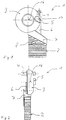
- FIGS. 1 and 2 are only an inner hinge part with a leg 2 shown. It however, it is understood that a complete hinge is the inner one Hinge part 1 and another outer hinge part (not shown), on which another mainstay (not shown) is attached.
- the inner hinge part 1 has a disk-shaped one Swivel body 3, a molded onto the swivel body Support body 6 and one on the swivel body 3 and Support body 6 integrally formed connector 7.
- the inner Hinge part 1 or the complete hinge (not shown) is preferably made of plastic, for example a plastic injection molding process.
- the connector 7 connects the inner hinge part with the support leg 2, the inner hinge part 1 with the supporting leg 2 is fixed via a connection catch 8.
- a lifting element 5 is provided on the inside of the inner hinge part 1, i.e. the side of the hinge, facing the user of the seating or reclining furniture .
- a lifting element 5 is provided on the inside of the inner hinge part 1, i.e. the side of the hinge, facing the user of the seating or reclining furniture.
- a lifting element 5 is provided on the inside of the inner hinge part 1, i.e. the side of the hinge, facing the user of the seating or reclining furniture.
- a lifting element 5 is eccentric, i.e
- lifting element 5 is in this concrete Exemplary embodiment in the position "3 o'clock” with a Distance from the pivot axis 16, i.e. eccentric, arranged.
- the pillar 2 points approximately vertically downwards.
- the lifting element 5 has approximately in this embodiment Form a "whistle” on, its mouthpiece in the direction of the downwardly extending pillar 2.
- a notch 4 is provided, which is approximately parallel to the longitudinal axis extends and the entire hinge (not shown) both on the inside and on the outside (not shown) towering over.
- the catch 4 preferably has the shape of a wave and is via a peg 17 in one piece at the edge of the disc-shaped inner hinge part 1 molded.
- the lifting element is also in a different position can be arranged.
- the choice of position will change especially on the specific design of the catches, the catch and orient the arrangement of one or more lifting surfaces.
- the position is of course always selected so that the described function of the lifting element ensures is.
- the lifting element can also have a different shape, such as round, rectangular, etc. It is crucial that the chosen one Form the described function in cooperation with the concrete Design of the catches, the catch and the one or fulfilled several lifting surfaces. Preferably, however, for that Lifting element chosen a shape that matches the shape of a "falling Tropfens "or a” whistle "resembles, in particular, to bring about a smooth operation.
- Fig. 3 shows the locking of the inner hinge part 1 according to 1 and 2 with an armrest 9 on a back part (not shown) of the seating or reclining furniture.
- the right armrest 9 there is a detent module 11 provided that approximately the shape of an elongated, downward open box.
- a detent module 11 In the upper area of the detent module 11 are numerous detents, such as a first detent 12 and a second detent 13 is provided.
- the locking module 11 is preferably molded in one piece into the armrest 9. In the Locking position of the inner hinge part 1 and the right armrest 9 shows the supporting leg 2 approximately in the direction of “5 o'clock” and one Another mainstay on the outer hinge part of the hinge (not shown) points approximately towards "7 o'clock".
- the upper Part of the inner hinge part 1 passes through the slit-shaped Opening of the locking module 11, and that on the inner Hinge part 1 molded catch 4 is in the first detent 12 the armrest 9 locked.
- the elongated slot of the detent module 11 faces on its inner hinge part Side a lifting surface 14, which extends over the entire length of the detent module 11 extends. 1 to 4
- the illustrated embodiment of the invention touches the lifting element 5 in the locked position of the foldable furniture, i.e. in the unfolded state, just the lifting surface 14.
- the armrest 9 is raised to fold the furniture and pulled slightly forward, as indicated by arrow 15 in FIG. 4 indicated that the direction of movement of the armrest 9 at the beginning folding the foldable furniture (not shown) shows.
- By lifting and pulling up the armrest 9 jumps the detent 4 from the catch 12 in the armrest 9 and is, as shown in Fig. 4, in an inherently unstable position between the first catch 12 and the second catch 13.
- the mainstay 2 moves from the "5 o'clock" position to the "4 o'clock” position, emphasizes this in the shape of an eccentric Lifting element 5, which acts on the lifting surface 14, the armrest 9 lightly and holds the catch 4 just above the back the lifting surface 14.
- the armrest 9 is when folded pulled further forward or upward, and the catch 4 slides on the top of the lifting surface 14 in the by the arrow 18 indicated direction of movement of the detent 4.
- the backrest is in front folding up by pressing the Armrest brought into its steepest position.
- Design and arrangement of the lifting element 5, in particular with regard to the position of the mainstay 2 achieved that the detent 4 when moving in the direction of Arrow 18, i.e. in the folded position of the foldable Furniture, at a defined distance from those above Latches of the armrest 9 is held and jerky and without jamming on the top of the lifting surface 14 in the folded Position slides.
Landscapes
- Health & Medical Sciences (AREA)
- Dentistry (AREA)
- General Health & Medical Sciences (AREA)
- Pivots And Pivotal Connections (AREA)
- Tables And Desks Characterized By Structural Shape (AREA)
Applications Claiming Priority (4)
| Application Number | Priority Date | Filing Date | Title |
|---|---|---|---|
| DE19833725 | 1998-07-27 | ||
| DE19833725 | 1998-07-27 | ||
| DE19836757 | 1998-08-13 | ||
| DE19836757A DE19836757C1 (de) | 1998-07-27 | 1998-08-13 | Klappbares Sitz- oder Liegemöbel, insbesondere Gartenmöbel |
Publications (2)
| Publication Number | Publication Date |
|---|---|
| EP0976347A2 true EP0976347A2 (fr) | 2000-02-02 |
| EP0976347A3 EP0976347A3 (fr) | 2001-03-07 |
Family
ID=26047709
Family Applications (1)
| Application Number | Title | Priority Date | Filing Date |
|---|---|---|---|
| EP99108430A Withdrawn EP0976347A3 (fr) | 1998-07-27 | 1999-04-29 | Aide, notamment pour plier une chaise de jardin |
Country Status (2)
| Country | Link |
|---|---|
| EP (1) | EP0976347A3 (fr) |
| DE (1) | DE19836757C1 (fr) |
Cited By (3)
| Publication number | Priority date | Publication date | Assignee | Title |
|---|---|---|---|---|
| EP1767121A1 (fr) * | 2005-09-21 | 2007-03-28 | Garpa Garten & Park Einrichtungen GmbH | Boîtier d' arrêt pour une chaise ou chaise longue |
| CN107307968A (zh) * | 2017-07-20 | 2017-11-03 | 深圳市福瑞斯保健器材有限公司 | 一种按摩椅 |
| US11241097B2 (en) | 2019-06-04 | 2022-02-08 | Yeti Coolers, Llc | Portable chair |
Family Cites Families (4)
| Publication number | Priority date | Publication date | Assignee | Title |
|---|---|---|---|---|
| FR1321713A (fr) * | 1961-04-11 | 1963-03-22 | Fauteuil garni d'une toile réglable et pourvu d'un dispositif automatique pour l'arrêt du dossier | |
| DE8436612U1 (de) * | 1984-12-14 | 1985-05-23 | Heinz Kettler Metallwarenfabrik Gmbh & Co, 4763 Ense | Klappsessel |
| DE8630586U1 (de) * | 1986-11-14 | 1987-01-08 | Karl Münkel GmbH & Co KG, 4837 Verl | Gelenkvorrichtung zur Anordnung zwischen einem Vorder- und einem Hinterbein eines Klappmöbels |
| US5560675A (en) * | 1994-01-13 | 1996-10-01 | Bemis Manufacturing Company | Folding rocking chair |
-
1998
- 1998-08-13 DE DE19836757A patent/DE19836757C1/de not_active Expired - Fee Related
-
1999
- 1999-04-29 EP EP99108430A patent/EP0976347A3/fr not_active Withdrawn
Cited By (5)
| Publication number | Priority date | Publication date | Assignee | Title |
|---|---|---|---|---|
| EP1767121A1 (fr) * | 2005-09-21 | 2007-03-28 | Garpa Garten & Park Einrichtungen GmbH | Boîtier d' arrêt pour une chaise ou chaise longue |
| CN107307968A (zh) * | 2017-07-20 | 2017-11-03 | 深圳市福瑞斯保健器材有限公司 | 一种按摩椅 |
| CN107307968B (zh) * | 2017-07-20 | 2023-08-04 | 深圳市福瑞斯健康科技有限公司 | 一种按摩椅 |
| US11241097B2 (en) | 2019-06-04 | 2022-02-08 | Yeti Coolers, Llc | Portable chair |
| US12144430B2 (en) | 2019-06-04 | 2024-11-19 | Yeti Coolers, Llc | Portable chair |
Also Published As
| Publication number | Publication date |
|---|---|
| DE19836757C1 (de) | 2000-03-23 |
| EP0976347A3 (fr) | 2001-03-07 |
Similar Documents
| Publication | Publication Date | Title |
|---|---|---|
| DE3630527C2 (fr) | ||
| DE2655916C2 (fr) | ||
| EP3256674B1 (fr) | Dispositif d'appui pour une trappe de meuble | |
| DE3705330A1 (de) | Tisch | |
| DE19644087A1 (de) | Lehnengelenkbeschlag für einen Kraftfahrzeugsitz | |
| DE69718853T2 (de) | Dekorplatte mit Vorrichtung zum senkrechten Verschieben längs der geschlossenen Tür eines eingebauten Gerätes | |
| EP1279352B1 (fr) | Table pliante | |
| EP0976347A2 (fr) | Aide, notamment pour plier une chaise de jardin | |
| DE2113398A1 (de) | In Form eines Tisches ausgebildetes Moebelstueck | |
| DE3339362C2 (de) | Kopfstütze für einen Kraftfahrzeugsitz | |
| DE19915315C2 (de) | Neigungsverstellvorrichtung für eine Fondsitzlehne | |
| DE60015290T2 (de) | Klappstuhl | |
| EP1106110A1 (fr) | Accoudoir à hauteur réglable pour siège notamment pour chaises de bureau | |
| EP0097733B1 (fr) | Escabeau verrouillable | |
| EP0002730B1 (fr) | Appui-tête, en particulier pour sièges de véhicules | |
| DE69408105T2 (de) | Mechanismus einer ausschwenkbaren Armlehne für Fahrzeugsitze | |
| EP0566982A1 (fr) | Chemin de glissement pour un connexion entre deux éléments | |
| DE3127310C2 (fr) | ||
| DE2638603A1 (de) | Schreibtisch, insbesondere kinderoder jugendschreibtisch | |
| EP0456008B1 (fr) | Cadre de pied pour un meuble pliant et articulation pour ce cadre | |
| DE3807959C2 (fr) | ||
| DE19508482C2 (de) | Schrank, insbesondere für medizinische oder zahnmedizinische Arbeitsplätze | |
| DE4342877C1 (de) | Verriegelbares Gelenk für vorklappbare Rückenlehnen von Sitzen, insbesondere von Fondsitzen für Kraftfahrzeuge | |
| DE10317133A1 (de) | Stapelbarer Reihenstuhl | |
| DE2520616C2 (de) | Klappbeschlag für Stützfüße von Möbeln |
Legal Events
| Date | Code | Title | Description |
|---|---|---|---|
| PUAI | Public reference made under article 153(3) epc to a published international application that has entered the european phase |
Free format text: ORIGINAL CODE: 0009012 |
|
| AK | Designated contracting states |
Kind code of ref document: A2 Designated state(s): AT BE DE ES FR GB IT NL |
|
| AX | Request for extension of the european patent |
Free format text: AL;LT;LV;MK;RO;SI |
|
| PUAL | Search report despatched |
Free format text: ORIGINAL CODE: 0009013 |
|
| AK | Designated contracting states |
Kind code of ref document: A3 Designated state(s): AT BE CH CY DE DK ES FI FR GB GR IE IT LI LU MC NL PT SE |
|
| AX | Request for extension of the european patent |
Free format text: AL;LT;LV;MK;RO;SI |
|
| 17P | Request for examination filed |
Effective date: 20010613 |
|
| AKX | Designation fees paid |
Free format text: AT BE DE ES FR GB IT NL |
|
| 17Q | First examination report despatched |
Effective date: 20030306 |
|
| STAA | Information on the status of an ep patent application or granted ep patent |
Free format text: STATUS: THE APPLICATION IS DEEMED TO BE WITHDRAWN |
|
| 18D | Application deemed to be withdrawn |
Effective date: 20030717 |