EP0976437A2 - Appareil et procédé pour la régénération d'un matériel de traitement d'une liquide - Google Patents
Appareil et procédé pour la régénération d'un matériel de traitement d'une liquide Download PDFInfo
- Publication number
- EP0976437A2 EP0976437A2 EP99114538A EP99114538A EP0976437A2 EP 0976437 A2 EP0976437 A2 EP 0976437A2 EP 99114538 A EP99114538 A EP 99114538A EP 99114538 A EP99114538 A EP 99114538A EP 0976437 A2 EP0976437 A2 EP 0976437A2
- Authority
- EP
- European Patent Office
- Prior art keywords
- liquid
- separator
- filter
- tank
- media
- Prior art date
- Legal status (The legal status is an assumption and is not a legal conclusion. Google has not performed a legal analysis and makes no representation as to the accuracy of the status listed.)
- Granted
Links
- 239000007788 liquid Substances 0.000 title claims abstract description 66
- 238000000034 method Methods 0.000 title claims abstract description 18
- 230000008929 regeneration Effects 0.000 title description 10
- 238000011069 regeneration method Methods 0.000 title description 10
- 239000008187 granular material Substances 0.000 claims abstract description 32
- 239000002002 slurry Substances 0.000 claims abstract description 18
- 239000000356 contaminant Substances 0.000 claims abstract description 9
- 238000013019 agitation Methods 0.000 claims description 6
- 238000001914 filtration Methods 0.000 claims description 5
- 238000004140 cleaning Methods 0.000 claims description 3
- 239000007787 solid Substances 0.000 claims description 2
- 239000000203 mixture Substances 0.000 claims 2
- 230000003116 impacting effect Effects 0.000 claims 1
- 230000001939 inductive effect Effects 0.000 claims 1
- 238000011001 backwashing Methods 0.000 description 3
- 230000002328 demineralizing effect Effects 0.000 description 2
- 239000012508 resin bead Substances 0.000 description 2
- 241000758789 Juglans Species 0.000 description 1
- 244000184861 Juglans nigra Species 0.000 description 1
- 235000013740 Juglans nigra Nutrition 0.000 description 1
- 235000009496 Juglans regia Nutrition 0.000 description 1
- 239000011324 bead Substances 0.000 description 1
- 230000000903 blocking effect Effects 0.000 description 1
- 238000009937 brining Methods 0.000 description 1
- 238000010276 construction Methods 0.000 description 1
- 239000012634 fragment Substances 0.000 description 1
- 230000005484 gravity Effects 0.000 description 1
- 238000004519 manufacturing process Methods 0.000 description 1
- 238000005192 partition Methods 0.000 description 1
- 230000000284 resting effect Effects 0.000 description 1
- 239000000725 suspension Substances 0.000 description 1
- 235000020234 walnut Nutrition 0.000 description 1
- XLYOFNOQVPJJNP-UHFFFAOYSA-N water Substances O XLYOFNOQVPJJNP-UHFFFAOYSA-N 0.000 description 1
Images

Classifications
-
- B—PERFORMING OPERATIONS; TRANSPORTING
- B01—PHYSICAL OR CHEMICAL PROCESSES OR APPARATUS IN GENERAL
- B01D—SEPARATION
- B01D24/00—Filters comprising loose filtering material, i.e. filtering material without any binder between the individual particles or fibres thereof
- B01D24/02—Filters comprising loose filtering material, i.e. filtering material without any binder between the individual particles or fibres thereof with the filter bed stationary during the filtration
- B01D24/10—Filters comprising loose filtering material, i.e. filtering material without any binder between the individual particles or fibres thereof with the filter bed stationary during the filtration the filtering material being held in a closed container
- B01D24/12—Downward filtration, the filtering material being supported by pervious surfaces
-
- B—PERFORMING OPERATIONS; TRANSPORTING
- B01—PHYSICAL OR CHEMICAL PROCESSES OR APPARATUS IN GENERAL
- B01D—SEPARATION
- B01D24/00—Filters comprising loose filtering material, i.e. filtering material without any binder between the individual particles or fibres thereof
- B01D24/46—Regenerating the filtering material in the filter
- B01D24/4668—Regenerating the filtering material in the filter by moving the filtering element
- B01D24/4673—Regenerating the filtering material in the filter by moving the filtering element using rotary devices or vibration mechanisms, e.g. stirrers
Definitions
- This invention concerns liquid treatment, and more particularly liquid treatment apparatus using granular media such as deep bed filters or deionizers, the bed of granular media disposed in a tank through which is passed a liquid to be treated thereby.
- granular media such as deep bed filters or deionizers
- the media In filters, the media must be cleaned periodically to remove accumulated filtered solids, as by backwashing the bed. This is also required in demineralizing apparatus where resin beads must be backwashed preparatory to brining the resin beads to reactivate the same. Backwashing can cause the loss of media if a too vigorous outflow is set up, but this limits the effectiveness of the cleaning of the media, which otherwise gradually becomes less effective.
- U.S. patent 5,171,443 issued on December 15, 1992 describes an improved regeneration process and system, particularly suited for filters using lightweight media such as crushed black walnut shells, but which is also applicable to deionizers.
- the liquid and media are vigorously agitated to form a slurry, and the liquid and contaminants are cause to flow out through openings in a separator, the openings sized to block the escape of media granules.
- the separator is a hollow cylindrical structure which is rotated within the slurry of liquid and media.
- the rotation of the separator prevents the media from clogging the separator strainer openings as the liquid flow draws the media against the openings, since the granules in suspension impact and dislodge the granules drawn against the separator openings.
- the above recited object is achieved by providing an annular, stationary separator having an inner diameter surface defined by screen formed with an array of strainer openings.
- An auxiliary rotor is disposed within the inside diameter of the separator with tips thereof closely spaced to the surface of the screen. The auxiliary rotor is rotated so as to create turbulence at the surface of the screen, causing the media granules in the slurry to be directed at the inner diameter surface, tending to dislodge any media granules which have been drawn onto the openings by the cleaning outflow through the separator during backwashing.
- the slurry may be formed by mechanical agitation, and in this case an agitator impeller may be driven by the same rotating shaft as the auxiliary rotor within the separator, or the auxiliary rotor may itself also act as a mechanical agitator toning the slurry.
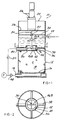
- a deep bed filter 10 is depicted diagrammatically, which includes a tank 12 defining an internal space containing a volume of granular filter media such as walnut shells or plastic beads of a predetermined uniform size forming a deep bed 14 in the lower region of the tank 12.
- the media bed 14 is supported on a discharge grating 16 at the bottom of the tank 12, the grating 16 having openings sufficiently small to prevent the particular size of media granules from passing out to an outlet 18.
- a wedgewire grate is preferred as described in the above referenced patent.
- a pump 20 may be connected to the outlet 18 to create a vacuum drawing liquid to be filtered from the tank 12 through the media bed 14. Alternately, a gravity feed may be used. Liquid to be filtered is directed into the upper region of the tank 12 via an inlet pipe 22.
- an agitator apparatus 24 in order to regenerate the media bed 14, is provided periodically operated to agitate the liquid and media to create a slurry composed of the liquid and the granular media.
- the agitator apparatus 24 includes an electric motor drive unit 26 supported on a top wall 28 of the tank 12.
- the drive unit 26 rotates a downwardly extending shaft 30, which may also have an intermediate bearing support 32 on a partition 34.
- a fixed annular separator 36 is mounted within the tank 12 at a central location ( Figure 2), supported on struts 38 and, outlet pipe 40.
- the inner diameter surface of the separator 36 is defined by a cylindrical screen 42 constructed with openings smaller than the size of the granular media.
- a wedge wire construction is preferred, as described in U.S. 5,171,443, in which tapered wires are welded to inner supports to form slits of sufficiently narrow width to prevent the escape of the media granules, but typically slightly larger than the openings of the grating 16 to allow media fragments to be eliminated during regeneration.
- An annular collector space 44 receives liquids and suspended contaminants passing out through the screen 42.
- the annular separator is fixed within the tank 12, attached to struts 38 and an outlet pipe 40, which opens into the collector space 44.
- the agitator apparatus 24 includes a pair of axially spaced sets of rotors 46A, 46B attached to the shaft.
- the lower rotor 46B is received within the inside diameter of the separator 36 with the tips thereof closely spaced to the surface 42. This spacing is sufficient to insure clearance as the rotor rotates but lose enough to create sufficient turbulence at the surface of the screen 42 to dislodge the media granules.
- the rotors 46A, 46B have downwardly facing impeller blade sets which when rotated at a sufficient velocity sets up a vertical recirculation, agitating the liquid and media, and causing a slurry to be formed of the liquid and media granules.
- the pump valve 48 is closed, and a backwash valve 50 is opened, causing the liquid and entrained contaminants to be drawn off through regeneration outlet 40.
- a make-up inflow of liquid is introduced via inlet pipe 22.
- the turbulence formed at the tips of the impeller blades of the lower rotor 46B causes the suspended granules to be forcefully directed at the granules drawn against the slits or openings in the screen 42 dislodging them to keep the granules cleared from the openings. This prevents a flow clogging buildup which otherwise would occur.
- FIG. 3 shows a pressurized deep bed liquid treatment apparatus 52, such as a deionizer in which a closed pressurized tank 54 contains a media bed 56 resting on a grating 58 over a central outlet 60. Liquid is directed under pressure into the tank interior through an inlet 62.
- a pressurized deep bed liquid treatment apparatus 52 such as a deionizer in which a closed pressurized tank 54 contains a media bed 56 resting on a grating 58 over a central outlet 60. Liquid is directed under pressure into the tank interior through an inlet 62.
- annular separator 64 is fixedly supported centrally within the tank 54, above the media bed 56, by a series of struts 66 and an outlet pipe 68.
- an agitator apparatus 70 has a rotor-impeller 72 driven by a drive unit 74 and shaft 76.
- the rotor impeller 72 is of larger diameter and is located below the separator 64 to enable agitation sufficient to form a slurry with the single rotor impeller 72.
- An auxiliary rotor 74 comprised of a set of four square edged blades each having an outer blade portion 76 are located with the blade edge closely adjacent the surface of the inner cylindrical screen 78 of the separator 64.
- the blades edges 76 sweep over the area just inside the surface of the screen 78 to create turbulence and a tangential flow tending to dislodge any granules drawn to the screen openings, and therby keep the screen 78 openings clear of media granules, as in the above described embodiment.
- the liquid treatment apparatus 52 can comprise a filtering and/or a demineralizing or deionizing water treatment system, as described above.
Landscapes
- Chemical & Material Sciences (AREA)
- Chemical Kinetics & Catalysis (AREA)
- Filtration Of Liquid (AREA)
- Devices And Processes Conducted In The Presence Of Fluids And Solid Particles (AREA)
Applications Claiming Priority (2)
| Application Number | Priority Date | Filing Date | Title |
|---|---|---|---|
| US123595 | 1998-07-27 | ||
| US09/123,595 US6287474B1 (en) | 1998-07-27 | 1998-07-27 | Liquid treatment media regeneration apparatus and process |
Publications (3)
| Publication Number | Publication Date |
|---|---|
| EP0976437A2 true EP0976437A2 (fr) | 2000-02-02 |
| EP0976437A3 EP0976437A3 (fr) | 2000-06-21 |
| EP0976437B1 EP0976437B1 (fr) | 2006-06-21 |
Family
ID=22409625
Family Applications (1)
| Application Number | Title | Priority Date | Filing Date |
|---|---|---|---|
| EP99114538A Expired - Lifetime EP0976437B1 (fr) | 1998-07-27 | 1999-07-23 | Appareil et procédé pour la régénération d'un matériel de traitement d'une liquide |
Country Status (4)
| Country | Link |
|---|---|
| US (1) | US6287474B1 (fr) |
| EP (1) | EP0976437B1 (fr) |
| CA (1) | CA2278957C (fr) |
| DE (1) | DE69932005T2 (fr) |
Cited By (4)
| Publication number | Priority date | Publication date | Assignee | Title |
|---|---|---|---|---|
| EP1138366A3 (fr) * | 2000-03-28 | 2001-11-28 | Chmiel, Horst, Prof. Dr.-Ing.habil. | Méthode pour séparer des composés tels que des matières en suspension et des composés colloidaux à partir de solutions |
| CN111298749A (zh) * | 2020-03-19 | 2020-06-19 | 中国热带农业科学院湛江实验站 | 一种甘蔗渣纤维素和木素离心分离同步处理筛选设备 |
| US10888806B2 (en) * | 2013-11-12 | 2021-01-12 | William Bloomfield | Scrubbing backwash filter |
| ES2936229A1 (es) * | 2022-10-31 | 2023-03-15 | Hidrotuit S L U | Dispositivo de limpieza de filtros para liquidos de candelas con sistema de regeneracion del medio filtrante |
Families Citing this family (8)
| Publication number | Priority date | Publication date | Assignee | Title |
|---|---|---|---|---|
| JP5201481B2 (ja) * | 2008-06-19 | 2013-06-05 | 株式会社ナガオカ | 水処理装置および水処理装置濾材層の洗浄方法 |
| NO347337B1 (no) | 2008-09-24 | 2023-09-18 | Siemens Energy Inc | Filterapparat med et valnøttskallfiltermedium |
| JP5845535B2 (ja) * | 2011-07-25 | 2016-01-20 | 株式会社ナガオカ | 水処理装置の上層洗浄装置および水処理装置濾材層の洗浄方法 |
| CN102784500B (zh) * | 2012-08-14 | 2014-08-06 | 湖南娄底泰阳科技有限公司 | 一种通用型受污染滤料的原位再生装置 |
| GB201301028D0 (en) * | 2012-12-04 | 2013-03-06 | Enhydra Ltd | Filtration arrangement and method |
| AT522058B1 (de) * | 2019-02-06 | 2020-10-15 | Sonnek Eng Gmbh | Filteranlage zur Behandlung von verunreinigten Flüssigkeiten |
| US11331616B2 (en) * | 2020-09-25 | 2022-05-17 | Mark Henderson | Pool filter assembly |
| US12208346B2 (en) * | 2021-10-11 | 2025-01-28 | Mycelx Technologies Corporation | Backwashable media bed filtration system and drop in retrofit kit for same |
Family Cites Families (8)
| Publication number | Priority date | Publication date | Assignee | Title |
|---|---|---|---|---|
| US748857A (en) * | 1904-01-05 | Filter | ||
| US632091A (en) * | 1899-04-01 | 1899-08-29 | Frederick Henry Bommarius | Filter. |
| US3550774A (en) * | 1968-01-09 | 1970-12-29 | Hydromation Eng Co | Method of and apparatus for filtering |
| US4162216A (en) * | 1977-10-25 | 1979-07-24 | Union Carbide Corporation | Process for removal of suspended solids from liquid |
| US4496464A (en) * | 1983-10-03 | 1985-01-29 | Hensley Clifford J | Filter apparatus and method |
| US4826609A (en) * | 1987-01-09 | 1989-05-02 | Hensley Clifford J | Filter media for filter systems |
| US5171443A (en) * | 1991-06-21 | 1992-12-15 | Bratten Jack R | Granular media regeneration apparatus |
| US5445740A (en) * | 1994-01-13 | 1995-08-29 | Malone; Ronald F. | Floating media biofilter |
-
1998
- 1998-07-27 US US09/123,595 patent/US6287474B1/en not_active Expired - Lifetime
-
1999
- 1999-07-23 EP EP99114538A patent/EP0976437B1/fr not_active Expired - Lifetime
- 1999-07-23 DE DE69932005T patent/DE69932005T2/de not_active Expired - Lifetime
- 1999-07-27 CA CA002278957A patent/CA2278957C/fr not_active Expired - Lifetime
Cited By (5)
| Publication number | Priority date | Publication date | Assignee | Title |
|---|---|---|---|---|
| EP1138366A3 (fr) * | 2000-03-28 | 2001-11-28 | Chmiel, Horst, Prof. Dr.-Ing.habil. | Méthode pour séparer des composés tels que des matières en suspension et des composés colloidaux à partir de solutions |
| US10888806B2 (en) * | 2013-11-12 | 2021-01-12 | William Bloomfield | Scrubbing backwash filter |
| US11291932B2 (en) | 2013-11-12 | 2022-04-05 | William Bloomfield | Scrubbing backwash filter |
| CN111298749A (zh) * | 2020-03-19 | 2020-06-19 | 中国热带农业科学院湛江实验站 | 一种甘蔗渣纤维素和木素离心分离同步处理筛选设备 |
| ES2936229A1 (es) * | 2022-10-31 | 2023-03-15 | Hidrotuit S L U | Dispositivo de limpieza de filtros para liquidos de candelas con sistema de regeneracion del medio filtrante |
Also Published As
| Publication number | Publication date |
|---|---|
| EP0976437A3 (fr) | 2000-06-21 |
| DE69932005T2 (de) | 2007-01-18 |
| CA2278957C (fr) | 2009-11-10 |
| CA2278957A1 (fr) | 2000-01-27 |
| DE69932005D1 (de) | 2006-08-03 |
| US6287474B1 (en) | 2001-09-11 |
| EP0976437B1 (fr) | 2006-06-21 |
Similar Documents
| Publication | Publication Date | Title |
|---|---|---|
| CA2070933C (fr) | Appareil et procede de regeneration de matieres granulees | |
| US6287474B1 (en) | Liquid treatment media regeneration apparatus and process | |
| US6780312B2 (en) | Filtration apparatus | |
| US7267767B2 (en) | Filtration apparatus | |
| JP3208632B2 (ja) | 箇水分離装置及び箇水分離方法 | |
| EP3795228B1 (fr) | Dispositif de filtration | |
| JPH0724223A (ja) | 分離機 | |
| NL8320165A (nl) | Inrichting voor universele waterbehandeling. | |
| JP5706851B2 (ja) | 濾材凝着物除去装置及び濾材凝着物除去方法 | |
| US5458775A (en) | Filtration apparatus for separating solids from liquid containing same | |
| EP0177451A2 (fr) | Appareil de séparation et de transport de solide de liquide | |
| JPH04176305A (ja) | 液体清浄装置 | |
| JPH11314016A (ja) | 濾過装置 | |
| US20260115630A1 (en) | Filtration apparatus | |
| JPH0679114A (ja) | 液体清浄装置 | |
| DK3150558T3 (en) | PROCEDURE FOR CLEANING USED WASHING WATER FROM CAR WASHING INSTALLATION AND CAR WASHING INSTALLATION | |
| KR100705963B1 (ko) | 여과재 재생선별장치 및 여과재 재생선별방법 | |
| JPH10165723A (ja) | ドラムスクリーン型ろ過装置 | |
| CN105364080B (zh) | 用于处理含油金属粉末的系统 | |
| JP3663458B2 (ja) | 生海苔の異物除去装置 | |
| JP2003311287A (ja) | 水処理装置 | |
| JPH1199304A (ja) | 砂濾過装置 | |
| JP3017245U (ja) | 液体清浄装置 | |
| JPH07124409A (ja) | 浮上ろ材を用いたろ過装置 | |
| JP3177882B2 (ja) | 濾過装置 |
Legal Events
| Date | Code | Title | Description |
|---|---|---|---|
| PUAI | Public reference made under article 153(3) epc to a published international application that has entered the european phase |
Free format text: ORIGINAL CODE: 0009012 |
|
| AK | Designated contracting states |
Kind code of ref document: A2 Designated state(s): DE FR GB |
|
| AX | Request for extension of the european patent |
Free format text: AL;LT;LV;MK;RO;SI |
|
| PUAL | Search report despatched |
Free format text: ORIGINAL CODE: 0009013 |
|
| AK | Designated contracting states |
Kind code of ref document: A3 Designated state(s): AT BE CH CY DE DK ES FI FR GB GR IE IT LI LU MC NL PT SE |
|
| AX | Request for extension of the european patent |
Free format text: AL;LT;LV;MK;RO;SI |
|
| 17P | Request for examination filed |
Effective date: 20000728 |
|
| AKX | Designation fees paid |
Free format text: DE FR GB |
|
| 17Q | First examination report despatched |
Effective date: 20020507 |
|
| GRAP | Despatch of communication of intention to grant a patent |
Free format text: ORIGINAL CODE: EPIDOSNIGR1 |
|
| GRAS | Grant fee paid |
Free format text: ORIGINAL CODE: EPIDOSNIGR3 |
|
| GRAA | (expected) grant |
Free format text: ORIGINAL CODE: 0009210 |
|
| AK | Designated contracting states |
Kind code of ref document: B1 Designated state(s): DE FR GB |
|
| REG | Reference to a national code |
Ref country code: GB Ref legal event code: FG4D |
|
| REF | Corresponds to: |
Ref document number: 69932005 Country of ref document: DE Date of ref document: 20060803 Kind code of ref document: P |
|
| ET | Fr: translation filed | ||
| PLBE | No opposition filed within time limit |
Free format text: ORIGINAL CODE: 0009261 |
|
| STAA | Information on the status of an ep patent application or granted ep patent |
Free format text: STATUS: NO OPPOSITION FILED WITHIN TIME LIMIT |
|
| 26N | No opposition filed |
Effective date: 20070322 |
|
| PGFP | Annual fee paid to national office [announced via postgrant information from national office to epo] |
Ref country code: GB Payment date: 20120723 Year of fee payment: 14 |
|
| PGFP | Annual fee paid to national office [announced via postgrant information from national office to epo] |
Ref country code: FR Payment date: 20120803 Year of fee payment: 14 Ref country code: DE Payment date: 20120828 Year of fee payment: 14 |
|
| GBPC | Gb: european patent ceased through non-payment of renewal fee |
Effective date: 20130723 |
|
| REG | Reference to a national code |
Ref country code: DE Ref legal event code: R119 Ref document number: 69932005 Country of ref document: DE Effective date: 20140201 |
|
| REG | Reference to a national code |
Ref country code: FR Ref legal event code: ST Effective date: 20140331 |
|
| PG25 | Lapsed in a contracting state [announced via postgrant information from national office to epo] |
Ref country code: GB Free format text: LAPSE BECAUSE OF NON-PAYMENT OF DUE FEES Effective date: 20130723 Ref country code: DE Free format text: LAPSE BECAUSE OF NON-PAYMENT OF DUE FEES Effective date: 20140201 |
|
| PG25 | Lapsed in a contracting state [announced via postgrant information from national office to epo] |
Ref country code: FR Free format text: LAPSE BECAUSE OF NON-PAYMENT OF DUE FEES Effective date: 20130731 |