EP0976455B1 - Antriebszahnritzel für einen Zahnkranz/Ritzel-Antrieb - Google Patents
Antriebszahnritzel für einen Zahnkranz/Ritzel-Antrieb Download PDFInfo
- Publication number
- EP0976455B1 EP0976455B1 EP99113460A EP99113460A EP0976455B1 EP 0976455 B1 EP0976455 B1 EP 0976455B1 EP 99113460 A EP99113460 A EP 99113460A EP 99113460 A EP99113460 A EP 99113460A EP 0976455 B1 EP0976455 B1 EP 0976455B1
- Authority
- EP
- European Patent Office
- Prior art keywords
- pinion
- elastically deformable
- annular
- components
- drive
- Prior art date
- Legal status (The legal status is an assumption and is not a legal conclusion. Google has not performed a legal analysis and makes no representation as to the accuracy of the status listed.)
- Expired - Lifetime
Links
Images
Classifications
-
- B—PERFORMING OPERATIONS; TRANSPORTING
- B02—CRUSHING, PULVERISING, OR DISINTEGRATING; PREPARATORY TREATMENT OF GRAIN FOR MILLING
- B02C—CRUSHING, PULVERISING, OR DISINTEGRATING IN GENERAL; MILLING GRAIN
- B02C17/00—Disintegrating by tumbling mills, i.e. mills having a container charged with the material to be disintegrated with or without special disintegrating members such as pebbles or balls
- B02C17/18—Details
- B02C17/24—Driving mechanisms
-
- F—MECHANICAL ENGINEERING; LIGHTING; HEATING; WEAPONS; BLASTING
- F16—ENGINEERING ELEMENTS AND UNITS; GENERAL MEASURES FOR PRODUCING AND MAINTAINING EFFECTIVE FUNCTIONING OF MACHINES OR INSTALLATIONS; THERMAL INSULATION IN GENERAL
- F16H—GEARING
- F16H1/00—Toothed gearings for conveying rotary motion
- F16H1/02—Toothed gearings for conveying rotary motion without gears having orbital motion
- F16H1/26—Special means compensating for misalignment of axes
-
- Y—GENERAL TAGGING OF NEW TECHNOLOGICAL DEVELOPMENTS; GENERAL TAGGING OF CROSS-SECTIONAL TECHNOLOGIES SPANNING OVER SEVERAL SECTIONS OF THE IPC; TECHNICAL SUBJECTS COVERED BY FORMER USPC CROSS-REFERENCE ART COLLECTIONS [XRACs] AND DIGESTS
- Y10—TECHNICAL SUBJECTS COVERED BY FORMER USPC
- Y10T—TECHNICAL SUBJECTS COVERED BY FORMER US CLASSIFICATION
- Y10T74/00—Machine element or mechanism
- Y10T74/19—Gearing
- Y10T74/19633—Yieldability in gear trains
Definitions
- the invention relates to a drive sprocket for a sprocket / pinion drive of rotary drums, such. Tube mills, wherein the pinion meshes with the ring gear.
- the arrangement of a bearing block is disclosed on a pedestal, wherein the bearing block is connected to the base via an elastic member.
- the elastic element can be filled with hydraulic fluid and emptied, which can compensate for malpositions of the bearing block.
- the FR 926,384 teaches the mounting of drive shafts for pinions in a pressure sleeve.
- the pressure sleeve is able to compensate for minor misalignment of the shaft and low radial play of the pinion.
- the invention has for its object to provide a pinion gear for a sprocket / pinion drive, which is simple in construction and yet able to adapt itself automatically as a joint to changing operating conditions of the meshing ring gear or the driven rotary drum.
- the drive sprocket is made self-adjusting in that the pinion on the pinion shaft and / or the pinion shaft bearings are resiliently mounted on both sides of the pinion and / or the pinion shaft bearing blocks over spatially elastically deformable components.
- the pinion from both end faces may have outgoing recesses in which around the pinion shaft circumference around annular elastically deformable components are arranged, via which the pinion is elastically resiliently supported on the pinion shaft surface.
- the drive pinion of the invention sits as on a ball joint, without the need for a complex structure with spherically curved spherical cap surfaces.
- the toothed pin according to the invention can even be resilient in the radial direction if required by means of the elastically deformable components such as a spring. In this case, the radial flexibility of the elastically deformable components can be set lower than the tooth stiffness of the pinion.
- the torque transmission can be separated from the transverse force transmission. Then, between the two arranged in the Ritzelstirnsanitary Scheme annular elastically deformable components a toothing between pinion and pinion shaft for torque transmission is arranged, which can be accomplished by an internal / external teeth as well as by the application of a feather key.
- a toothing between pinion and pinion shaft for torque transmission is arranged, which can be accomplished by an internal / external teeth as well as by the application of a feather key.
- the pinion gear according to the invention but also the functions of the torque transmission and the transverse force transmission can be combined in one element. To accomplish this task, the two arranged in Ritzelstirnsanitary Scheme annular elastically deformable components such as so-called clamping sets between the pinion and pinion shaft can be braced.
- the spatially elastically deformable annular components can consist of an elastic bushing as a structural unit, with a metallic outer ring and inner ring, between which an elastomeric ring suitable elastic modulus is clamped concentrically.
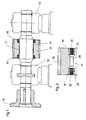
- the drive pinion 10 is rotatably supported on both sides by means of its pinion shaft 11 in Wellenlagerböcken 12 and 13. With 14 of the flange for flanging the pinion shaft 11 is indicated on a transmission countershaft for the pinion drive.
- the pinion 10 with its external teeth has outgoing from both end faces recesses in which around the pinion shaft circumference around annular elastically deformable components 15 and 16 are arranged, via which the pinion 10 is resiliently supported on the surface of the pinion shaft 11.
- the components 15, 16 are spatially elastically deformable, so that the pinion 10 can respond to all possible changing operating conditions of the meshing with the ring gear of the tube mill as a spring compliant.
- a toothing 17 between the pinion 10 and pinion shaft 11 is arranged, which may consist of an internal / external toothing or from a feather key arrangement.
- the pinion 10 the torque transmission and the lateral force transmission are separated.
- the elastically deformable components 15 and 16 of the FIG. 1 can each consist of an elastic bushing as a structural unit, with at least one metallic outer ring 18 and 19 and at least one metallic inner ring 20 and 21, between which an elastomer ring 22 and 23 is clamped concentrically with a suitable modulus of elasticity.
- the arranged between the two elastic bushing teeth 24 between pinion 10 and pinion shaft 11 for torque transmission is in FIG. 2 shown schematically.
Landscapes
- Engineering & Computer Science (AREA)
- General Engineering & Computer Science (AREA)
- Mechanical Engineering (AREA)
- Food Science & Technology (AREA)
- Gears, Cams (AREA)
- Gear Transmission (AREA)
Applications Claiming Priority (2)
| Application Number | Priority Date | Filing Date | Title |
|---|---|---|---|
| DE19832933 | 1998-07-22 | ||
| DE19832933A DE19832933B4 (de) | 1998-07-22 | 1998-07-22 | Antriebszahnritzel für einen Zahnkranz/Ritzel-Antrieb |
Publications (2)
| Publication Number | Publication Date |
|---|---|
| EP0976455A1 EP0976455A1 (de) | 2000-02-02 |
| EP0976455B1 true EP0976455B1 (de) | 2008-05-07 |
Family
ID=7874897
Family Applications (1)
| Application Number | Title | Priority Date | Filing Date |
|---|---|---|---|
| EP99113460A Expired - Lifetime EP0976455B1 (de) | 1998-07-22 | 1999-07-13 | Antriebszahnritzel für einen Zahnkranz/Ritzel-Antrieb |
Country Status (4)
| Country | Link |
|---|---|
| US (1) | US6186019B1 (da) |
| EP (1) | EP0976455B1 (da) |
| DE (2) | DE19832933B4 (da) |
| DK (1) | DK0976455T3 (da) |
Families Citing this family (4)
| Publication number | Priority date | Publication date | Assignee | Title |
|---|---|---|---|---|
| DE102006042301B4 (de) * | 2006-09-08 | 2018-02-22 | Ellergon Antriebstechnik Gmbh | Membranausgleichskupplung und Lochlaibungsverbindung |
| US9739352B2 (en) | 2011-07-29 | 2017-08-22 | Flow International Corporation | Drive system with coupler assembly and method |
| CN103230818B (zh) * | 2013-04-28 | 2014-10-22 | 昆明学院 | 一种新型节能球磨机 |
| EP3027933B1 (en) | 2013-08-02 | 2019-11-13 | Kumera Drives Oy | Drive mechanism for a toothed ring |
Family Cites Families (26)
| Publication number | Priority date | Publication date | Assignee | Title |
|---|---|---|---|---|
| CH231753A (de) * | 1942-03-02 | 1944-04-15 | Kloeckner Humboldt Deutz Ag | Antriebseinrichtung für Drehtrommeln, insbesondere für Rohrmühlen. |
| DE738695C (de) * | 1942-03-03 | 1943-08-27 | Kloeckner Humboldt Deutz Ag | Antrieb fuer Drehtrommeln, insbesondere Rohrmuehlen |
| DE869892C (de) * | 1943-06-22 | 1953-03-09 | Rudolf Spieth | Spannvorrichtung |
| US2544809A (en) * | 1945-04-10 | 1951-03-13 | American Viscose Corp | Overload release clutch |
| FR926384A (fr) * | 1946-05-07 | 1947-09-30 | Anciens Ets Savy | Broyeur à boulets |
| AT261646B (de) * | 1964-01-13 | 1968-05-10 | Voest Ag | Ausgleichsgetriebe für kippbare metallurgische Öfen |
| DD59439A1 (de) * | 1967-01-23 | 1967-12-20 | Werner Moeller | Elastische Lagerung von Zahnrädern, insbesondere von Planetenrädern |
| FR1583426A (da) * | 1968-02-29 | 1969-10-31 | ||
| US3554045A (en) * | 1969-06-27 | 1971-01-12 | Dura Corp | Momentary flexible overload release device for a motor drive |
| DE2024436A1 (de) * | 1970-05-20 | 1971-12-02 | Peter O | Nabenbefestigung, insbesondere fur ein Zahnrad |
| DE7026178U (de) * | 1970-07-11 | 1970-10-15 | Miag Muehlenbau & Ind Gmbh | Zahnradantrieb fuer drehrohre. |
| US3682015A (en) * | 1971-03-05 | 1972-08-08 | Falk Corp | Pinion construction |
| US4234237A (en) * | 1977-03-29 | 1980-11-18 | Maschinenfabrik Andritz Aktiengesellschaft | Bearing for heavy steel drums, in particular decorticating drums |
| US4854184A (en) * | 1983-11-07 | 1989-08-08 | Jessup Thurman W | Support system for shaft |
| DE3413812A1 (de) * | 1984-04-12 | 1985-10-24 | Th. Bergmann & Co, 2084 Rellingen | Kupplung zur verbindung der abtriebswelle eines schrittmotors mit durch diesen anzutreibenden koerpern insbesondere rotationssymmetrischen koerpern |
| DE3419967C2 (de) * | 1984-05-29 | 1986-07-10 | Boge Gmbh, 5208 Eitorf | Elastisches Gelenk, Kupplung oder dergleichen |
| DE3433905A1 (de) * | 1984-09-14 | 1986-03-27 | Krupp Polysius Ag, 4720 Beckum | Drehtrommel |
| DE3534940A1 (de) * | 1984-11-07 | 1986-05-22 | A. Friedr. Flender Gmbh & Co Kg, 4290 Bocholt | Antriebsvorrichtung fuer ein drehrohr mit leistungsverzweigung |
| JPH0616986Y2 (ja) * | 1986-08-11 | 1994-05-02 | 本田技研工業株式会社 | エンジンの始動装置 |
| DE3821023A1 (de) * | 1988-06-22 | 1989-12-28 | Bosch Gmbh Robert | Andrehvorrichtung fuer brennkraftmaschinen |
| DE9000530U1 (de) * | 1990-01-18 | 1990-03-01 | Krupp Polysius Ag, 4720 Beckum | Laufring zur Drehlagerung von relativ großen Drehtrommeln |
| DE4108480A1 (de) * | 1991-03-15 | 1992-09-17 | Freudenberg Carl Fa | Elastische kupplung mit zusammengefasster lagerung und drehbegrenzung |
| DE9215898U1 (de) * | 1992-11-24 | 1993-02-11 | A. Friedr. Flender AG, 46395 Bocholt | Leistungsverzweigende Getriebeanordnung |
| US5452622A (en) * | 1993-02-09 | 1995-09-26 | Magi, L.P. | Stress dissipation gear |
| JP3625849B2 (ja) * | 1993-11-26 | 2005-03-02 | 東芝機械株式会社 | テーブル旋回駆動装置 |
| US5607023A (en) * | 1994-12-13 | 1997-03-04 | Milwaukee Electric Tool Corp. | Impact absorption mechanism for power tools |
-
1998
- 1998-07-22 DE DE19832933A patent/DE19832933B4/de not_active Expired - Fee Related
-
1999
- 1999-07-13 DE DE59914745T patent/DE59914745D1/de not_active Expired - Lifetime
- 1999-07-13 DK DK99113460T patent/DK0976455T3/da active
- 1999-07-13 EP EP99113460A patent/EP0976455B1/de not_active Expired - Lifetime
- 1999-07-19 US US09/356,579 patent/US6186019B1/en not_active Expired - Lifetime
Also Published As
| Publication number | Publication date |
|---|---|
| US6186019B1 (en) | 2001-02-13 |
| DE59914745D1 (de) | 2008-06-19 |
| DE19832933A1 (de) | 2000-01-27 |
| EP0976455A1 (de) | 2000-02-02 |
| DE19832933B4 (de) | 2007-10-18 |
| DK0976455T3 (da) | 2008-09-08 |
Similar Documents
| Publication | Publication Date | Title |
|---|---|---|
| DE60211965T2 (de) | Elektrisches Servo-Lenkungssystem | |
| DE2657575C3 (de) | Parallelwellenantrieb | |
| AT520740B1 (de) | Zahnrad | |
| DE19741226A1 (de) | Wellen-Zahnradgetriebe vom Zylinderhut-Typ | |
| DE102016118245A1 (de) | Zahnradanordnung | |
| DE60217764T2 (de) | Umlaufrädervorrichtung zur Geschwindigkeitsreduzierung der Motorausgangswelle | |
| WO2009100978A1 (de) | Anlaufscheibe für planetenräder eines planetengetriebes | |
| EP0219683A2 (de) | Dichtungsanordnung | |
| EP1119092A2 (de) | Kupplung eines Motors mit einem Generator | |
| WO1998022725A1 (de) | eÄLZLAGER MIT GERAUSCHDÄMPFUNG | |
| DE19715026B4 (de) | Elastischer Antrieb für Druckmaschinen | |
| EP0976455B1 (de) | Antriebszahnritzel für einen Zahnkranz/Ritzel-Antrieb | |
| DE3121797C2 (de) | Mischtrommellagerung für einen Transportbetonmischer | |
| DE9106339U1 (de) | Hoch drehelastische Wellenkupplung | |
| DE60003093T2 (de) | Kupplung für Pumpe und Motor | |
| DE102004042235B4 (de) | Lageranordnung einer Windenergieanlage | |
| EP1691095B1 (de) | Axiale Isolierung für ein kardanisches Kreuzgelenk | |
| DE29909603U1 (de) | Kettenrad für Gelenkketten und Dämpfungseinrichtung | |
| DE19504456B4 (de) | Antriebsgetriebe einer Zylindergruppe und Verfahren zum Antrieb der Zylinder | |
| DE10352322B4 (de) | Schalldämpfungsanordnung innerhalb eines Antriebsstrangs | |
| WO2000075063A1 (de) | Kettenrad für gelenkketten und dämpfungseinrichtung | |
| DE19753576B4 (de) | Zahnkranz für einen Zahnkranzantrieb von Drehtrommeln | |
| DE102019115283A1 (de) | Ein Differentialgetriebe und ein Fahrzeug mit einem Differentialgetriebe | |
| EP1691099B1 (de) | Axiale Isolierung für ein kardanisches Kreuzgelenk | |
| DE2233065A1 (de) | Antrieb fuer konverter, drehtrommeln, plattenbaender o. dgl |
Legal Events
| Date | Code | Title | Description |
|---|---|---|---|
| PUAI | Public reference made under article 153(3) epc to a published international application that has entered the european phase |
Free format text: ORIGINAL CODE: 0009012 |
|
| AK | Designated contracting states |
Kind code of ref document: A1 Designated state(s): DE DK FR |
|
| AX | Request for extension of the european patent |
Free format text: AL;LT;LV;MK;RO;SI |
|
| 17P | Request for examination filed |
Effective date: 20000725 |
|
| AKX | Designation fees paid |
Free format text: DE DK FR |
|
| RAP1 | Party data changed (applicant data changed or rights of an application transferred) |
Owner name: KHD HUMBOLDT WEDAG GMBH |
|
| 17Q | First examination report despatched |
Effective date: 20061211 |
|
| RAP1 | Party data changed (applicant data changed or rights of an application transferred) |
Owner name: KHD HUMBOLDT WEDAG GMBH |
|
| GRAP | Despatch of communication of intention to grant a patent |
Free format text: ORIGINAL CODE: EPIDOSNIGR1 |
|
| GRAS | Grant fee paid |
Free format text: ORIGINAL CODE: EPIDOSNIGR3 |
|
| GRAA | (expected) grant |
Free format text: ORIGINAL CODE: 0009210 |
|
| AK | Designated contracting states |
Kind code of ref document: B1 Designated state(s): DE DK FR |
|
| REF | Corresponds to: |
Ref document number: 59914745 Country of ref document: DE Date of ref document: 20080619 Kind code of ref document: P |
|
| PLBE | No opposition filed within time limit |
Free format text: ORIGINAL CODE: 0009261 |
|
| STAA | Information on the status of an ep patent application or granted ep patent |
Free format text: STATUS: NO OPPOSITION FILED WITHIN TIME LIMIT |
|
| 26N | No opposition filed |
Effective date: 20090210 |
|
| PGFP | Annual fee paid to national office [announced via postgrant information from national office to epo] |
Ref country code: DK Payment date: 20110720 Year of fee payment: 13 |
|
| PGFP | Annual fee paid to national office [announced via postgrant information from national office to epo] |
Ref country code: FR Payment date: 20120806 Year of fee payment: 14 Ref country code: DE Payment date: 20120728 Year of fee payment: 14 |
|
| REG | Reference to a national code |
Ref country code: DK Ref legal event code: EBP Effective date: 20130731 |
|
| REG | Reference to a national code |
Ref country code: DE Ref legal event code: R119 Ref document number: 59914745 Country of ref document: DE Effective date: 20140201 |
|
| REG | Reference to a national code |
Ref country code: FR Ref legal event code: ST Effective date: 20140331 |
|
| PG25 | Lapsed in a contracting state [announced via postgrant information from national office to epo] |
Ref country code: DE Free format text: LAPSE BECAUSE OF NON-PAYMENT OF DUE FEES Effective date: 20140201 |
|
| PG25 | Lapsed in a contracting state [announced via postgrant information from national office to epo] |
Ref country code: FR Free format text: LAPSE BECAUSE OF NON-PAYMENT OF DUE FEES Effective date: 20130731 |
|
| PG25 | Lapsed in a contracting state [announced via postgrant information from national office to epo] |
Ref country code: DK Free format text: LAPSE BECAUSE OF NON-PAYMENT OF DUE FEES Effective date: 20130731 |